Note: Descriptions are shown in the official language in which they were submitted.
CA 02640389 2008-07-25
WO 2007/106146 PCT/US2006/042965
-1-
METHOD FOR COOLING AN INTERNAL COMBUSTION ENGINE HAVING
EXHAUST GAS RECIRCULATION AND CHARGE AIR COOLING
DESCRIPTION
Technical Field
This invention relates to a cooling system for internal combustion engines
used in trucks and other motor vehicles and, in particular, to a cooling
system
utilizing a charge air cooler and an exhaust gas cooler in combination with a
radiator.
Background Art
Stricter emissions requirements have forced the use of partial exhaust gas
recirculation as a means of achieving more complete combustion, and this has
necessitated the cooling of the recirculated exhaust gas before introducing it
into the
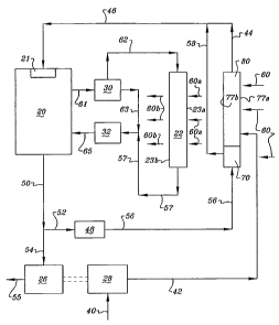
engine intake manifold. Fig. 1 shows a typical heavy duty truck cooling system
having a liquid- cooled exhaust gas recirculation (EGR) cooler. The engine
cooling
system comprises an internal combustion engine 20 utilizing conventional
liquid
engine coolant. The liquid coolant heated- by operation of the engine exits
the
engine through line or hose 61 and passes through a thermostat 30. If the
coolant is
below the thermostat set temperature it is passed through line 63 to coolant
pump
32 and back through line 65 to the engine. If the coolant is above the
thermostat set
temperature, it is sent through line 62 to otherwise conventional air cooled
radiator
22 where ambient air flow 60, 60a and 60b passes through the radiator by means
of
a fan (not shown) as well as movement of the vehicle in which the engine is
mounted. The cooled liquid coolant then passes through lines 57 and 59 back to
the coolant pump before returning to the engine.
For mixture with the fuel, the engine utilizes inlet air 40 that passes
through
a filter (not shown) and is compressed by a turbo- or supercharger. The engine
system depicted herein utilizes engine exhaust gases exiting through lines 50
and
54 in a turbocharger in which turbine 26 drives compressor 28. After passing
CA 02640389 2008-07-25
WO 2007/106146 PCT/US2006/042965
-2-
through the turbine blades, the exhaust gas exits through line 55 to the
exhaust
system (not shown). After compression, the charge air passes through line 42
to air-
to-air charge air cooler (CAC) 24 mounted upstream of radiator 22. The cooled
charge air then exits CAC 24 through line 44.
A portion of the exhaust gas exiting through line 50 passes through line 52
and through an EGR valve 48. The exhaust gas then passes through line 56 to
EGR
cooler 34, which is a liquid-to-air heat exchanger that cools the hot exhaust
gases
using the cooled liquid engine coolant entering through line 57. Because
brazed
aluminum heat exchanger construction is not capable of withstanding the high
exhaust gas temperatures, typically, such an EGR cooler must be of high-
temperature heat exchanger construction; that is, made of materials able to
withstand higher temperatures than brazed aluminum, such as brazed stainless
steel, brazed cupro-nickel, brazed copper, and the like. The cooled
recirculated
exhaust gas then exits the EGR cooler through line 58, where it mixes with the
cooled charge air from line 44. The mixture of cooled recirculated exhaust gas
and
charge air then proceeds through line 46 to the intake manifold 21 of engine
20 for
mixture with the fuel and then to the engine combustion chambers.
This system has two disadvantages: 1) the high cost of stainless steel or
other
high temperature EGR cooler construction and 2) the cooling limitation
resulting
from the use of engine coolant at approximately 180 F.
Fig. 2 shows another prior art heavy duty truck cooling system in which the
exhaust gas which is to be recirculated is mixed with the hot charge air
coming from
the turbocharger for cooling in an air-cooled heat exchanger. Since the liquid
engine coolant does not need to cool the exhaust gas, the liquid engine
coolant
passes through line 57 from radiator 22 and back to coolant pump 32 for return
to
the engine. The hot exhaust gas exiting EGR valve 48 passes through line 56
where
it combines and mixes with compressed, heated charge air in line 41 exiting
compressor 28. The combined heated exhaust gas and charge air then passes
through line 43 to a brazed stainless steel combination exhaust gas
recirculation and
charge air cooler 24' upstream of radiator 22. Alternatively, the combination
CA 02640389 2008-07-25
WO 2007/106146 PCT/US2006/042965
-3-
exhaust gas recirculation and charge air cooler may be made of other high
temperature construction such as the aforementioned brazed cupro-nickel or
brazed
copper. After the charge air and exhaust gas are cooled by ambient air 60
passing
through CAC 24', the cooled combined exhaust gas and charge air then pass
through
line 45 to engine intake manifold 21. This approach does allow the
recirculated
exhaust gas and charge air to be cooled to a temperature close to that of the
ambient
cooling air, which will always be much less than that of the engine coolant.
However, it does not solve the expense problem related to high temperature-
resistant construction and, in fact, increases the expense by requiring
stainless steel
or other expensive high temperature material to be used in a very large
combination
EGR/CAC.
In addition to having high material costs, prior systems and methods of
cooling charge air and/or recirculated exhaust gases in an internal combustion
engine have not been able to individually tailor thermal performance of
individual
heat exchanger units in a space-saving package.
Disclosure of Invention
Bearing in mind the problems and deficiencies of the prior art, it is
therefore
an object of the present invention to provide an improved system and method of
cooling an internal combustion engine, including charge air cooling and
exhaust
gas cooling, which achieves cooling of the charge air and the recirculated
exhaust
gas to near ambient temperatures.
It is another object of the present invention to provide a system and method
of cooling an internal combustion engine, including charge air cooling and
exhaust
gas cooling, which allows the use of lower cost materials for the charge air
and
exhaust gas coolers.
A further object of the present invention is to provide a system and method
of cooling charge air and recirculated exhaust gas in an internal combustion
engine
which saves space in a combined radiator, CAC and EGR cooler package.
CA 02640389 2008-07-25
WO 2007/106146 PCT/US2006/042965
-4-
Yet another object of the present invention is to provide a combined heat
exchanger package for an internal combustion engine that permits tailoring of
thermal performance of individual heat exchanger units within the package.
Still other objects and advantages of the invention will in part be obvious
and will in part be apparent from the specification.
The above and other objects, which will be apparent to those skilled in the
art, are achieved in the present invention which is directed to a method and
apparatus for cooling charge air from a turbo- or supercharger and exhaust gas
recirculated from an exhaust gas recirculation valve in an internal combustion
engine comprising providing a radiator for air cooling of liquid engine
coolant from
the internal combustion engine and providing parallel charge air and exhaust
gas
heat exchanger units. The charge air heat exchanger unit has aluminum tubes
and
fins for air cooling the charge air, and the exhaust gas heat exchanger unit
having
tubes and fins made of a material resistant to higher operating temperatures
than
aluminum for air cooling the exhaust gas. The charge air heat exchanger and
the
exhaust gas heat exchanger units are each disposed adjacent a face of the
radiator
to permit ambient air to flow in series through the radiator and the charge
air and
exhaust gas heat exchanger units. The method then includes passing the charge
air
from the turbo- or supercharger through the charge air heat exchanger unit to
cool
the charge air, passing the exhaust gas from the exhaust gas recirculation
valve
through the exhaust gas heat exchanger unit to cool the exhaust gas, and
combining
the cooled charge air and cooled exhaust gas for passage into an intake
manifold on
the engine.
Preferably, the exhaust gas heat exchanger unit has tubes and fins made of
stainless steel. The radiator may comprise two units, with the charge air heat
exchanger unit being disposed adjacent a face of one radiator unit and the
exhaust
gas heat exchanger unit being disposed adjacent a face of the other radiator
unit.
The charge air heat exchanger unit and the exhaust gas heat exchanger unit may
have different core styles, such as different core depth, type of fins, fin
spacing, fin
count, tube spacing and tube count.
CA 02640389 2008-07-25
WO 2007/106146 PCT/US2006/042965
-5-
The charge air and exhaust gas heat exchanger units may be disposed in
parallel adjacent a same face of the radiator to permit ambient air to flow in
series
through the radiator and the charge air and exhaust gas heat exchanger units.
The charge air and exhaust gas heat exchanger units may be disposed
downstream of the radiator with respect to ambient air flow to permit ambient
air to
flow in series first through the radiator and subsequently through the charge
air and
exhaust gas heat exchanger units, or vice-versa.
The charge air and exhaust gas heat exchanger units may be disposed
adjacent opposite faces of the radiator, with the charge air heat exchanger
unit
being disposed upstream of the radiator and the exhaust gas heat exchanger
unit
being disposed downstream of the radiator. This permits ambient air to flow in
series first through charge air heat exchanger unit having aluminum tubes and
fins
and then through the radiator, and permits ambient air to flow in series
through the
radiator and subsequently through the exhaust gas heat exchanger unit having
tubes
and fins made of the higher temperature resistant material. The radiator may
alternately comprise two units, with the charge air heat exchanger unit being
disposed upstream adjacent one radiator unit and the exhaust gas heat
exchanger
unit being disposed downstream adjacent the other radiator unit. The charge
air
heat exchanger unit and the exhaust gas heat exchanger unit may have different
core styles, and each radiator unit may have a different core style.
Alternatively, the charge air and exhaust gas heat exchanger units may be a
first set disposed downstream of the radiator with respect to ambient air flow
to
permit ambient air to flow in series first through the radiator and
subsequently
through the first set of charge air and exhaust gas heat exchanger units.
There may
be further provided a second set of charge air and exhaust gas heat exchanger
units,
wherein both heat exchanger units in the second set have aluminum tubes and
fins
for air cooling the charge air and the exhaust gas. The second set of charge
air and
exhaust gas heat exchanger units are disposed upstream of the radiator to
permit
ambient air to flow in series first through the second set of charge air and
exhaust
gas heat exchanger units and subsequently through the radiator. The partially
CA 02640389 2008-07-25
WO 2007/106146 PCT/US2006/042965
-6-
cooled charge air from the charge air heat exchanger unit downstream of the
radiator is passed through the second charge air heat exchanger unit upstream
of
the radiator to further cool the charge air. The partially cooled exhaust gas
from the
exhaust gas heat exchanger unit downstream of the radiator is passed through
the
second exhaust gas heat exchanger unit upstream of the radiator to further
cool the
exhaust gas before combining the cooled charge air and cooled exhaust gas for
passage to the intake manifold of the engine. At least one of the charge air
heat
exchanger units or exhaust gas heat exchanger units may have a different core
style.
The radiator may comprises two units, with the first set of charge air and
exhaust
gas heat exchanger units downstream of the radiator being disposed adjacent
one
radiator unit and the second set of charge air and exhaust gas heat exchanger
units
upstream of the radiator being disposed adjacent the other radiator unit. Each
radiator unit may have a different core style.
In another aspect, the present invention is directed to a method and
apparatus for cooling charge air from a turbo- or supercharger and exhaust gas
recirculated from an exhaust gas recirculation valve in an internal combustion
engine comprising providing a radiator for air cooling of liquid engine
coolant from
the internal combustion engine and providing a pair of combined charge air
cooler
and exhaust gas cooler heat exchanger units. A first one of the heat exchanger
units
has tubes and fins made of a material able to withstand higher operating
temperatures than aluminum, and the second of the heat exchanger units has
aluminum tubes and fins. The heat exchanger units are disposed adjacent the
radiator to permit ambient air to flow in series through the radiator and the
heat
exchanger units. The method includes combining the charge air from the turbo-
or
supercharger with the exhaust gas recirculated from the exhaust gas
recirculation
valve, passing the combined charge air and exhaust gas through the first heat
exchanger unit having the tubes and fins made of the higher temperature
resistant
material to partially cool the combined charge air and exhaust gas, passing
the
partially cooled combined charge air and exhaust gas through the second heat
exchanger unit having the aluminum tubes and fins to cool the combined charge
air
CA 02640389 2008-07-25
WO 2007/106146 PCT/US2006/042965
-7-
and exhaust gas, and passing the combined cooled charge air and exhaust gas
into
an intake manifold on the engine.
The heat exchanger unit having tubes and fins made of the higher
temperature resistant material, preferably stainless steel, may be disposed
downstream of the radiator with respect to ambient cooling air flow to permit
ambient air to flow in series first through the radiator and subsequently
through the
heat exchanger unit having tubes and fins made of the higher temperature
resistant
material. The heat exchanger unit having aluminum tubes and fins may be
disposed upstream of the radiator with respect to ambient cooling air flow to
permit
ambient air to flow in series first through the heat exchanger unit having
aluminum
tubes and fins and subsequently through the radiator.
The radiator may comprises two units, with the first heat exchanger unit
being disposed adjacent a face of one radiator unit and the second heat
exchanger
unit being disposed adjacent a face of the other radiator unit. Each of the
first and
second heat exchanger units may have a different core style, and each radiator
unit
may have a different core style.
In a further aspect, the present invention provides a method and apparatus
for cooling engine coolant and charge air from a turbo- or supercharger in an
internal combustion engine comprising providing a radiator for cooling engine
coolant having opposite front and rear core faces through which ambient air
flows,
and opposite upper and lower ends adjacent the faces, and providing a charge
air
cooler for cooling charge air having upper and lower units. Each charge air
cooler
unit has opposite front and rear core faces through which ambient air may
flow,
and opposite upper and lower ends adjacent the faces. The upper charge air
cooler
unit is disposed in overlapping relationship and adjacent to the upper end of
the
radiator, wherein one face at the upper end of the radiator is disposed
adjacent one
face of the upper charge air cooler unit, and the lower charge air cooler unit
is
disposed in overlapping relationship and adjacent to the lower end of the
radiator
with the upper and lower ends of the lower charge air cooler unit being
oriented in
the same direction as the upper and lower ends of the radiator, wherein the
other
CA 02640389 2008-07-25
WO 2007/106146 PCT/US2006/042965
-~-
face at the lower end of the radiator is disposed adjacent one face of the
lower
charge air cooler unit. Each charge air cooler unit has a different core style
selected
from the group consisting of core depth, type of fins, fin spacing, fin count,
tube
spacing and tube count. The charge air cooler units are operatively connected
such
that the charge air may flow therebetween. The method includes flowing the
engine coolant through the radiator to cool the engine coolant, flowing the
charge
air from the turbo- or supercharger in sequence through the charge air heat
exchanger units to cool the charge air, and flowing cooling air through the
heat
exchanger assembly such that the cooling air flows in series through the upper
end
of the radiator and the upper charge air cooler unit, and the cooling air
flows in
series through the lower charge air cooler unit and the lower end of the
radiator. At
least one of the charge air cooler units may include cooling for recirculated
exhaust
gas.
In yet another aspect, the present invention provides a method and
apparatus for cooling engine coolant and charge air from a turbo- or
supercharger in
an internal combustion engine comprising providing a radiator having upper and
lower units for cooling engine coolant, with each radiator unit having
opposite front
and rear core faces through which ambient cooling air flows, a depth between
the
front and rear faces, and opposite upper and lower ends adjacent the faces.
The
radiator units are operatively connected such that the engine coolant may flow
therebetween. There is also provided a charge air cooler having upper and
lower
units for cooling charge air, with each charge air cooler unit having opposite
front
and rear core faces through which cooling air may flow, and opposite upper and
lower ends adjacent the faces. The upper charge air cooler unit is disposed in
overlapping relationship and adjacent to the upper radiator unit with the
upper and
lower ends of the upper charge air cooler unit, wherein one face of the upper
radiator unit is disposed adjacent one face of the upper charge air cooler
unit, and
the lower charge air cooler unit is disposed in overlapping relationship and
adjacent to the lower radiator unit, wherein the other face of the lower
radiator unit
is disposed adjacent one face of the lower charge air cooler unit. Each charge
air
CA 02640389 2008-07-25
WO 2007/106146 PCT/US2006/042965
-9-
cooler unit has a different core style selected from the group consisting of
core
depth, type of fins, fin spacing, fin count, tube spacing and tube count. The
charge
air cooler units are operatively connected such that the charge air may flow
therebetween. The method then includes flowing the engine coolant in sequence
through the radiator units to cool the engine coolant, flowing the charge air
from
the turbo- or supercharger in sequence through the charge air heat exchanger
units
to cool the charge air, and flowing cooling air through the heat exchanger
assembly
such that the cooling air flows in series through the upper radiator unit and
the
upper charge air cooler unit, and the cooling air flows in series through the
lower
charge air cooler unit and the lower radiator unit. At least one of the charge
air
cooler units may include cooling for recirculated exhaust gas. Each radiator
unit
may have a different core style.
Brief Description of the Drawings
The features of the invention believed to be novel and the elements
characteristic of the invention are set forth with particularity in the
appended
claims. The figures are for illustration purposes only and are not drawn to
scale.
The invention itself, however, both as to organization and method of
operation,
may best be understood by reference to the detailed description which follows
taken in conjunction with the accompanying drawings in which:
Fig. 1 is a partially schematic view of a prior art internal combustion engine
cooling system.
Fig. 2 is a partially schematic view of another prior art internal combustion
engine cooling system showing in side elevational view the relative placement
of a
combined exhaust gas and charge air cooler with respect to the radiator.
Fig. 3 is a graphical depiction of percent of maximum heat transfer as a
function of number of rows of tubes in a single heat exchanger core.
Fig. 4 is a partially schematic view of one embodiment of the internal
combustion engine cooling system of the present invention showing in side
CA 02640389 2008-07-25
WO 2007/106146 PCT/US2006/042965
-10-
elevational view the relative placement of exhaust gas and charge air coolers
with
respect to the radiator.
Fig. 5 is a perspective view of the charge air cooler and EGR gas cooler used
in some embodiments of the internal combustion engine cooling system of the
present invention.
Fig. 6 is a partially schematic view of another embodiment of the internal
combustion engine cooling system of the present invention showing in side
elevational view the relative placement of an exhaust gas cooler and a charge
air
cooler with respect to the radiator.
Fig. 7 is a side elevational view of a modification of the radiator/ charge
air
cooler and exhaust gas cooler package of Fig. 6, where the radiator is split
into two
units, and the entire package is two cores deep.
Fig. 8 is a partially schematic view of a further embodiment of the internal
combustion engine cooling system of the present invention showing in side
elevational view the relative placement of combined exhaust gas and charge air
coolers with respect to the radiator.
Fig. 9 is a side elevational view of a modification of the radiator/ charge
air
cooler and exhaust gas cooler package of Fig. 8, where the radiator is split
into two
units, and the entire package is two cores deep.
Fig. 10 is a sectional plan view of portions of the cores of the upper and
lower combined EGR/CAC radiator units of Fig. 9 showing differences in tube
spacing, tube minor diameter and core depth.
Fig. 11 is a sectional elevational view of portions of the cores of the upper
and lower combined EGR/CAC radiator units of Fig. 9 showing differences in fin
count, fin thickness and fin louver angle.
Fig. 12 is a partially schematic view of yet another embodiment of the
internal combustion engine cooling system of the present invention showing in
side
elevational view the relative placement of exhaust gas and charge air coolers
with
respect to the radiator.
CA 02640389 2008-07-25
WO 2007/106146 PCT/US2006/042965
-11-
Fig. 13 is a side elevational view of a modification of the radiator/ charge
air
cooler and exhaust gas cooler package of Fig. 12, where the radiator is split
into
two units, and the entire package is two cores deep.
Mode(s) for Carrying Out the Invention
In describing the preferred embodiments of the present invention, reference
will be made herein to Figs. 3-13 of the drawings in which like numerals refer
to
like features of the invention.
The management of airflow through an air cooled heat exchanger or
packaged group of heat exchangers is important to the heat transfer
performance of
the heat exchanger unit or package. The development of airflow paths that
optimize temperature potential is vital in the design of space-saving cooling
systems
within the constraints of typical fan/shroud arrangements in heavy-duty
trucks.
Before considering airflow in the EGR/CAC/radiator heat exchanger
packages disclosed herein, it is useful to examine airflow in a single core
heat
exchanger. Fig. 3 depicts the relationship of heat transfer as a function of
number
of rows of tubes in a heat exchanger core. A vehicle radiator having only one
row
of core tubes is initially assumed, wherein the depth in the direction of
airflow is
0.50 in. (13mm). If the tube spacing across the face of the core is about 0.44
in.
(11 mm) and the fin spacing is about 14 fins per in. (5.5 fins/cm), then the
airflow
through the core, caused either by the action of a fan or by ram air as a
result of
vehicle motion, will be reasonably high. If increased heat transfer
performance is
desired, a radiator with an additional row of tubes may be used, making the
core
two rows deep. The cooling airflow will decrease slightly because of the added
resistance of the deeper core, but the overall heat transfer will be greatly
increased.
However, as illustrated in Fig. 3, as the core is made even deeper, to three,
four,
five and six rows deep, cooling air flow is greatly reduced, to the point
where
adding another row will result in decreased, rather than increased, heat
transfer
performance. This occurs because with the low airflow and deep core, the
cooling
air reaching the last row of tubes is already heated to the point where it is
CA 02640389 2008-07-25
WO 2007/106146 PCT/US2006/042965
-12-
ineffective in creating further cooling. In such a case, improved performance
can
be achieved by reducing the core depth to manage, or increase, the cooling
airflow,
and by other methods and means, discussed further below.
The internal combustion engine cooling system of the present invention
achieves cooling of the ciiarge air and the recirculated exhaust gas to near
ambient
temperatures, but permits the use of lower cost materials overall. Fig. 4
shows a first
embodiment of the cooling system in which the air-cooled stainless steel or
other
high temperature-resistant exhaust gas cooler is separate from, and in
parallel with,
an aluminum charge air cooler, with respect to the cooling ambient air flow.
As used
herein, the term "ambient air" includes all of the cooling air as it passes
through the
radiator, exhaust gas cooler and charge air cooler heat exchanger units, even
though
it is heated as it passes through the fins of the heat exchanger units.
Instead of
combining the hot exhaust gas from EGR valve 48 with the heated charge air, or
separately cooling the heated exhaust gas utilizing the liquid engine coolant,
the
heated exhaust gas passes through line 56 to an air-to-air exhaust gas heat
exchanger
70 for cooling. The term "line" as used herein is intended to include hoses,
tubing,
piping and the like typically used to carry fluids in an internal combustion
engine
environment, such as the exhaust gas, charge air and liquid coolant described
herein. Exhaust gas cooler 70 is disposed upstream of radiator 22 and receives
inlet
ambient cooling air 60. Radiator 22 is typically a down flow type radiator,
wherein
engine coolant enters through an upper manifold extending substantially the
entire
width of the radiator, is then distributed in the core through vertical,
downwardly
extending tubes connected by cooling fins, so that ambient cooling air may
flow
from the front face 23a of the core through and out of the rear face 23b.
After being
cooled by the ambient air, the coolant then collects in an attached lower
manifold
also extending across the width of the radiator. Alternatively, the radiator
may be an
up-flow type radiator, with coolant flow in the opposite direction, or a cross
flow
type radiator with coolant flow through core tubes extending horizontally
between
horizontally opposed manifolds.
CA 02640389 2008-07-25
WO 2007/106146 PCT/US2006/042965
-13-
In parallel with and above exhaust gas cooler 70, and also in front of and in
series with radiator 22 with respect to the ambient air flow, charge air
cooler heat
exchanger 80 receives the heated, compressed charge air through line 42, where
it
is also cooled by ambient air 60 entering through the CAC/EGR cooler front
face
77a. As a result, ambient air 60a exiting from the CAC/EGR cooler rear face
77b is
heated by both the exhaust gas and charge air coolers before it passes through
radiator 22, where it is further heated and exits 60b from the radiator. The
cooled
exhaust gas exits exhaust gas cooler 70 through line 58, and the cooled charge
air
exits charge air cooler 80 through line 44. The cooled charge air then
combines
with the cooled exhaust gas and passes through line 46 to engine intake
manifold
21. Alternatively, the EGR cooler 70 and CAC 80 may be disposed on the
opposite
side of radiator 22, i.e., downstream of the radiator with respect to the
ambient air
flow.
In this embodiment, the recirculated exhaust gas and the charge air are
combined after the charge air cooler, rather than before it as in the prior
art system
of Fig. 2. This system and method avoid having to make a combination exhaust
gas
and charge air cooler entirely out of stainless steel or other high
temperature-resistant
material. Instead, while the exhaust gas cooler is still made of stainless
steel or the
like, the charge air cooler may be made of aluminum.
The radiator, CAC and EGR cooler shown in the embodiment of Fig. 4 (as
well as in the subsequent embodiments described below) are preferably secured
to
each other to create a combined heat exchanger package. The air-to-air heat
exchanger units used for the exhaust gas cooler 70 and charge air cooler 80
are
shown in more detail in Fig. 5. Charge air cooler 80 includes upper and lower
horizontally extending manifolds 81, 82 respectively, which distribute or
collect the
charge air passing through spaced, vertically extending tubes 83 connecting
the
manifolds. These tubes may be two (2) rows deep, as shown in Fig. 5, or any
other
configuration, to achieve desired core depth d,. A serpentine cooling fin
array 84
(also of depth di) between adjacent tubes 83 extending across the face of
charge air
cooler 80 comprises the charge air cooler core, which transfers the heat from
the
CA 02640389 2008-07-25
WO 2007/106146 PCT/US2006/042965
-14-
charge air within the tubes to the ambient air passing between the tubes 83
and
over the fins 84. The vertical spacing between the serpentine fins determines
the
desired fin count. The fins may be of the louvered, lanced-offset, wavy (non-
louvered) or other type, or plate fins may be used instead. The manifolds have
openings 85, 86 for passage of charge air into or out of the manifolds. The
CAC
may be configured as an upflow unit, where heated charge air is received in
inlet
86 of manifold 82 where it passes upward through tubes 83 and from manifold 81
through outlet 85 as cooled charge air. Alternatively, the CAC may be
configured
as a downflow unit, where the heated charge air flow is received in inlet 85
and
flows in a reverse direction out through outlet 86 as cooled charge air.
In a construction analogous to that of the charge air cooler, exhaust gas
cooler 70 has upper and lower manifolds 71 and 72, with the former having
inlet/outlet 75 and the latter having inlet/outlet 76. Tubes 73 carry the
exhaust gas
between manifolds 71 and 72, and fins 74 between adjacent tubes 73 permit
passage of the cooling ambient air therebetween to cool the hot exhaust gases
passing within tube 73. The core has depth d2, and tubes 73 and fins 74 may be
modified as described in connection with CAC 80. As with the charge -air
cooler,
EGR cooler 70 may be set up as a downflow unit, so that the hot exhaust gases
are
passed through inlet 75 downward through the tubes and cooled exhaust gas
passes
outward through outlet 76, or as an upflow unit where the exhaust gas travels
in the
reverse direction.
As shown in Fig. 5, both exhaust gas cooler 70 and charge air cooler 80
have a horizontal width, measured in the direction of the manifolds, which is
greater than the vertical height of each of the units, measured between the
manifolds. Improved heat exchanger performance as a result of reduced charge
air
pressure drop, may be obtained by utilizing tubes which are as short as
possible
and as numerous as possible, given the configuration of the heat exchanger
units.
As shown in this embodiment, both the exhaust gas and charge air coolers
employ
tubes which are oriented with the shorter vertical height of each of the units
so that
there is a larger number of shorter tubes. Alternatively, both the exhaust gas
and
CA 02640389 2008-07-25
WO 2007/106146 PCT/US2006/042965
-15-
charge air coolers may be cross-flow units with exhaust gas flow through
horizontally oriented tubes extending between vertically oriented manifolds on
either side of the charge air cooler.
Preferably, charge air cooler 80 and exhaust gas cooler 70 are sized so that
their respective widths w, and w2 are each the same as the width of the
radiator
with which they are packaged. Preferably, CAC 80 and EGR cooler 70 are
connected to each other, as indicated by the arrows, to create a single unit
that is
positioned adjacent to the radiator. The combined heights of the charge air
cooler
80 and EGR cooler 70, h, and hz respectively, may be up to the height of the
radiator. Typically, the height h, of the charge air cooler is greater than
the height
h2 of the exhaust gas cooler 70 when there are greater cooling requirements
for the
charge air versus the recirculated exhaust gas.
In addition to modifying the heights and widths of the CAC and EGR
coolers, the cores of each may be modified as desired to achieve the desired
thermal cooling properties for the combined radiator/CAC/EGR cooler package.
For
example, the core depths, the type of fins, the fin spacing and count, and the
tube
spacing and count for each CAC and EGR cooler may be the same as or different
from other CAC and EGR coolers in the package.
The manifolds, tubes and fins of charge air cooler 80 may be made of
aluminum, either as a conventional fully brazed CAC or with brazed tubes and
fins
and grommeted tube-to-header joints. The latter is disclosed in U.S. Patent
Nos.
5,894,649, 6,330,747 and 6,719,037, the disclosures of which are hereby
incorporated by reference. Because the exhaust gases to be cooled are
considerably hotter than the charge air to be cooled by charge air cooler 80,
exhaust gas cooler 70 is preferably not made of aluminum, and instead the
manifolds, tubes and fins are made of stainless steel or other high
temperature-
resistant material for additional heat resistance and product life. Since only
the
portion of the heat exchanger package used to cool the exhaust gas is made of
stainless steel or the like, the cost of the combined exhaust gas cooler 70
and
CA 02640389 2008-07-25
WO 2007/106146 PCT/US2006/042965
-16-
charge air cooler 80 is less, since the charge air cooler portion is made of
lower
cost aluminum.
Fig. 6 depicts another embodiment of the cooling system of the present
invention. Instead of combining the exhaust gas cooler with the charge air
cooler
in a common unit adjacent the same face of the radiator, exhaust gas cooler 70
is
placed adjacent the face of the radiator opposite the charge air cooler, which
is
disposed near the upper end of the radiator. As with the previous embodiment,
charge air cooler 80 is disposed upstream of radiator 22 so that ambient air
60
passes through front face 87a and out of rear face 87b as partially heated
ambient
air 60a. The height of the charge air cooler 80 is less than that of radiator
22, so
that a portion of radiator 22 (here shown as the lower portion) receives
ambient air
60 which does not pass through the charge air cooler. The remaining portions
of
the radiator 22 receive ambient air 60a which has been heated partially by
passage
in series through charge air cooler 80. Disposed downstream of radiator 22 is
exhaust gas cooler 70, here shown disposed adjacent to the lower portion of
the
radiator 22 which receives the unheated ambient air 60. The ambient air 60b
partially heated after passage through rear face 23b of radiator 22 then
passes in
series through the front face 77a and the fins and tubes of exhaust gas cooler
70,
and exits 60c at a higher temperature from rear face 77b. However, the
difference
in temperature between the exhaust gas and the heated cooling air 60b is still
sufficient to allow good heat transfer. The cooled exhaust gas exits the
cooler 70
and passes through line 58 where it combines with the cooled charge air in
line 44.
The combined mixture then passes through line 46 into engine intake manifold
21.
The height h, of charge air cooler 80 and the height h2 of exhaust gas cooler
70 are preferably selected so that the combined height h, + 112 is
approximately
equal to the height of radiator 22, and the two coolers 70, 80 do not overlap
with
each other. Placing the exhaust gas cooler behind the radiator in this
embodiment
improves the radiator cooling performance by avoiding heating of the radiator
by
the exhaust gas cooler. As with the previous embodiment, exhaust gas cooler 70
is
CA 02640389 2008-07-25
WO 2007/106146 PCT/US2006/042965
-17-
made of stainless steel or other high temperature-resistant material and the
charge
air cooler 80 is made of lower cost aluminum.
A modification of the embodiment of Fig. 6 is shown in Fig. 7, where charge
air cooler 80 and exhaust gas cooler 70 are the same, but the radiator is
split into
two different portions or units, upper rear unit 22a and lower front unit 22b,
in a
manner similar to that shown in U.S. Patent Publication No. US2005-0109484-A1,
the disclosure of which is hereby incorporated by reference. In the front
(with
respect to ambient air flow 60), charge air cooler 80 is above and has front
and rear
faces substantially planar with those of lower radiator unit 22b, and in the
rear
exhaust gas cooler 70 is below and has front and rear faces substantially
planar with
those of upper radiator unit 22a. Variations in core depth in the individual
units
may change the planar alignment slightly. The heights and widths of upper
radiator
unit 22a and charge air cooler 80 are substantially the same, as are the
heights and
widths of lower radiator unit 22b and exhaust gas cooler 70. Each radiator
unit
22a, 22b has a construction similar to the full radiator previously described
above,
but with shorter height. As in the case of the CAC and EGR coolers described
in
Fig. 5, the core of each unit 22a, 22b may be varied in depth, type of fins,
fin
spacing and count, and tube spacing and count, compared to the other, to
achieve
the desired balance of thermal cooling properties in the package. An
additional
line 62a passes partially cooled engine coolant from upper unit 22a to lower
unit
22b. The modification in Fig. 7 results in a combined radiator/CAC/EGR cooler
package that is only two cores deep, as opposed to the three core deep package
of
Fig. 6. This saving in core depth has benefits in that fan 90 exhausting the
heated
ambient air 60d may be spaced farther back from the rear core face, and
thereby
provide for higher air flow and better air flow distribution over the entire
core face
of the heat exchanger package.
A further embodiment of the present invention is depicted in Fig. 8. Instead
of cooling the exhaust gas and heated charge air in separate heat exchangers,
the
heated exhaust gas from line 56 is combined with the heated charge air exiting
the
compressor in line 41, and the mixture of heated exhaust gas and charge air
passes
CA 02640389 2008-07-25
WO 2007/106146 PCT/US2006/042965
-18-
through line 43 to first combined exhaust gas and charge air cooler 80a.
Combined
exhaust gas and charge air cooler 80a is disposed downstream of radiator 22,
in a
location corresponding to the lower portion of the radiator 22 that receives
fresh
ambient cooling air 60 through front face 23a. After ambient air 60 passes
through
the radiator rear face 23b and exits as partially heated ambient air 60b, it
then
passes in series through the front face 87a and the fins and tubes of the
combined
cooler 80a and exits as heated ambient air 60c from the rear face 87b. The
combined cooler 80a is constructed in a manner similar to charge air cooler 80
shown in Fig. 5, except that it is made of stainless steel or other high
temperature-
resistant material instead of aluminum since it is carrying gases at a higher
temperature.
As it exits cooler 80a, the combined exhaust gas and charge air is partially
cooled. It then travels through line 69 where it then enters a second combined
exhaust gas and charge air cooler 80b, disposed upstream of radiator 22.
Combined cooler 80b is shown adjacent the front face 23a, near the upper
portion
of radiator 22 so that it does not overlap with the first combined cooler 80A
adjacent the rear face 23b, near the lower portion of radiator 22. The
partially
cooled combined exhaust gas and charge air is then subject to maximum cooling
by ambient air 60, which passes through the front face 87a and the tubes and
fins of
cooler 80b, and exits rear face 87b as heated ambient air 60a to cool radiator
22 in
series: The arrangement of this split exhaust gas and charge air cooler is
similar to
that of the split charge air cooler disclosed in U.S. Patent Publication No.
US2005-
0109483-Al, the disclosure of which is hereby incorporated by reference. The
cooled combined exhaust gas and charge air then exits cooler 80b through line
45
to intake manifold 21. Since the combined exhaust gas and charge air received
in
cooler 80b is already partially cooled, cooler 80b does not need to be made of
stainless steel or other high temperature-resistant material, and can be made
of
aluminum. Preferably, heights and locations of coolers 80a and 80b are
selected so
that they do not overlap with one another, and their combined heights are
approximately equal to the height of radiator 22. Additionally, the core
styles, i.e.,
CA 02640389 2008-07-25
WO 2007/106146 PCT/US2006/042965
-19-
the core depth, the type of fins, the fin spacing and count, and the tube
spacing and
count, may be varied and tailored for each unit 80a, 80b, to obtain the
desired air
flow split and unit performance. For example, the front unit 80b may have a
lower
fin count and/or core depth (the latter shown by the reduced core depth of
front
face 87a') to limit the heating of the ambient air that passes through the
core of the
radiator, whereas the rear unit 80a may have a higher fin count and/or core
depth
(the latter shown by the increased core depth of rear face 87b') to derive
maximum
cooling of the combined exhaust gas and charge air. Effects of variation in
core
parameters are discussed further below. This system and method provides
maximum heat transfer performance with material cost savings over the prior
art
system and method of Fig. 2 because at least half of the combined exhaust gas
and
charge air cooler can be made with the lower cost aluminum construction.
Fig. 9 shows a modification of the embodiment of Fig. 8. In a manner
similar to the modification of Fig. 7, the radiator is split into two units
22a, 22b,
with connecting line 62a, so that the combined radiator/CAC/EGR cooler package
is
only two cores deep with respect to ambient air flow 60. Again, the front and
rear
faces of the vertically matched units 80b, 22b and 22a, 80a, respectively, are
in
substantially the same planes (except for any variations in core depth in the
individual units) and the heights and widths of the horizontally matched
units, 22a,
80b and 80a, 22b, respectively, are substantially the same. This again saves
space
and permits more optimal mounting of fan 90 for better flow through the
package
of the cooling ambient air.
In a packaged group of heat exchangers, as depicted in Figs. 4, 6, 7, 8 and 9,
it is particularly important to manage the airflow splits among the various
heat
exchangers in order to achieve optimum heat transfer performance. In a package
with split radiator and split charge air cooler as shown in Fig. 9, it may be
desirable,
in order to achieve optimum radiator performance, to manage the cooling
airflow
through the front charge air cooler by lowering its core resistance. This will
result
in the minimum impact of the front charge air cooler upon the radiator core
behind,
CA 02640389 2008-07-25
WO 2007/106146 PCT/US2006/042965
-20-
and will provide optimized cooling airflow to the radiator, resulting in
optimum
radiator heat transfer.
The flow of cooling air through a heat exchanger core, for example the cores
of radiator units 22a, 22b and charge air cooler units 80a, 80b, may be
managed in
a number of different ways, each affecting the core airflow resistance or the
airflow
resistance of the entire airflow path. For example, airflow through a given
heat
exchanger may be increased by increasing the core resistance of a heat
exchanger
in parallel with it or by decreasing its own core resistance or the core
resistance of a
heat exchanger in series with it. Various core parameters may be varied in any
of
the heat exchangers of Figs. 4, 6, 7, 8 and 9 to achieve a finltube system
with the
desired cooling airflow resistance.
As described above in connection with Fig. 9, and as shown in Fig. 10
where the cores of the upper and lower combined EGR/CAC units are juxtaposed
for comparison, a decreased depth d of the core of upper combined exhaust gas
and charge air cooler unit 80b (in front of the upper radiator unit) decreases
core
resistance and increases cooling airflow, while increased core depth D of
lower
combined exhaust gas and charge air cooler unit 80c (behind the lower radiator
unit) increases core resistance and decreases cooling airflow. Also, increased
CAC
tube 83 spacing S and smaller CAC tube 83 minor diameter m on unit 80b (both
measured in a direction across the face of the core) decrease core resistance
and
increase cooling airflow, whereas decreased tube spacing s and increased tube
minor diameter M on unit 80a increase core resistance and decrease cooling
airflow. Variations to the core fins also affect cooling airflow resistance.
For
example, as shown in Fig. 11 with the cores of EGR/CAC units 80a and 80b again
juxtaposed, increased fin 73a count per unit vertical distance C, increased
fin
louver 73a' angles A and increased fin thickness T on unit 80a increase core
resistance and decrease cooling airflow, as compared to the decreased fin 73b
count per unit vertical distance c, decreased fin louver 73b' angles a and
decreased
fin thickness t on unit 80b. The use of louvered fins 73a', 73b' increases
core
CA 02640389 2008-07-25
WO 2007/106146 PCT/US2006/042965
-21-
resistance and decreases cooling airflow as compared to flat, dimpled or wavy
style
fins.
Each radiator unit 22a, 22b in Fig. 9 likewise may have different core styles,
such as core depth, type of fins, fin spacing, fin count, tube spacing and
tube count,
in the same manner as described in connection with the EGR/CAC units.
The core area of the EGR, CAC and radiator cores has a direct effect on
airflow management, but in a much more complex manner than the items
mentioned above. In the embodiment shown in Fig. 9, the charge air cooler core
areas may be the same as the radiator core areas, i.e., be fully overlapping
with
respect to cooling air flow. On the other hand, the charge air cooler cores
may
extend beyond the radiator core areas in one or more directions, i.e., be
overhanging or non-overlapping with respect to cooling air flow, or the
radiator
core areas may extend beyond those of the charge air coolers in any direction.
The
airflow resistance of a given core is inversely proportional to its area.
However, the
greater the area of a heat exchanger which is overlapped by another heat
exchanger, the greater will be the airflow resistance of the two heat
exchangers.
Increased overlapping results in increased airflow resistance and increased
overhanging results in decreased airflow resistance through the heat
exchangers in
the package.
It has been found that the static head loss through the heat exchanger
package along each airflow path is equivalent. Thus, face velocities that
drive
convection increase or decrease to achieve this balance. The split radiator
and
charge air cooler configurations having multiple different fin/tube systems
provide
the flexibility to modify air velocities for best results. Optimized
application-
specific results may be obtained not only through heat exchanger core
arrangements, but also through use of different fin/tube systems in each heat
exchanger unit.
A further embodiment of the present invention which combines some of the
characteristics of previous embodiments is depicted in Fig. 12. In a manner
similar
to the embodiment of Fig. 4, the exhaust gas and heated charge air are not
CA 02640389 2008-07-25
WO 2007/106146 PCT/US2006/042965
-22-
combined, but are instead cooled in connected parallel heat exchangers located
adjacent to the radiator. However, in a manner similar to that of the
embodiment
of Fig. 8, the heat exchangers for each of the exhaust gas and charge air are
split
into units downstream and upstream of radiator 22. Recirculated exhaust gas
from
line 56 is first cooled in exhaust gas cooler 70' downstream of radiator 22,
and,
separately, heated charge air from line 42 is first cooled in charge air
cooler 80', in
parallel with cooler 70' and also downstream of the radiator. The downstream
exhaust gas and charge air coolers 70' and 80', respectively, are connected to
form
a single unit like that shown in Fig. 5, except that they are inverted, so
that the
exhaust gas cooler portion is above the charge air cooler portion. As with the
previous description of the embodiment of Fig. 5, the exhaust gas cooler 70'
is
made of stainless steel or other high temperature-resistant material, since it
receives
the hotter exhaust gas, and the charge air cooler unit 80' is made of
aluminum. The
exhaust gas cooler 70' and charge air cooler unit 80' are located along the
lower
portion adjacent to and downstream of rear face 23b of radiator 22,
corresponding
to the region in which radiator 22 receives unheated ambient air 60. The
partially
heated ambient air 60b from the lower portion of radiator 22 passes in series
through front face 77a and the tubes and fins of both exhaust gas cooler 70'
and
charge air cooler 80', and exits as further heated ambient air 60c from the
rear face
77b of coolers 70'/80'.
The partially cooled exhaust gas then exits exhaust gas cooler 70' through
line 69a, where it enters the inlet of second, upstream exhaust gas cooler
70". The
partially cooled charge air exits downstream charge air cooler 80' and travels
through line 69b to the inlet of second, upstream charge air cooler 80".
Ambient
air 60 passes through the front face 77a of both coolers 70" and 80", located
adjacent the upper portion of the radiator, to respectively cool the exhaust
gas and
charge air. The partially heated ambient air 60a then exits the rear face 77b
of
coolers 70"/ 80" and passes in series through the front face 23a at the upper
portion of radiator 22. The cooled exhaust gas then exits from exhaust gas
cooler
70" through line 58, and the cooled charge air exits from charge air cooler
80"
CA 02640389 2008-07-25
WO 2007/106146 PCT/US2006/042965
-23-
through line 44, and are combined and passed through line 46 to engine intake
manifold 21.
The upstream exhaust gas cooler 70" and charge air cooler 80" are also
constructed in connected parallel units 70"/80" similar to that shown in Fig.
5,
except inverted. However, since the exhaust gas is already partially cooled,
it does
not have an excessively high temperature. Therefore, the upstream exhaust gas
cooler 70' need not be made of stainless steel or other high temperature-
resistant
material, and may be constructed of aluminum, similar to that of charge air
cooler
80". The location and combined height of the downstream exhaust gas and charge
air coolers 70'/80' and the location and combined height of the upstream
exhaust
gas and charge air coolers 70"/80" are selected so that the downstream and
upstream connected units do not overlap with one another, and so that the sum
of
the combined heights of the units is approximately equal to the height of the
radiator. As with the other embodiments previously described, core styles such
as
core depth, type of fins, fin spacing and count, and tube spacing and count
may be
varied and tailored for each unit 70', 70", 80', 80", to obtain the desired
heat
transfer performance.
In a modification similar to those of Figs. 7 and 9, Fig, 13 shows a
modification of the embodiment of Fig. 12 in which the radiator is again split
into
two units 22a, 22b, connected by line 62a, so that the combined
radiator/CAC/EGR
cooler package is only two cores deep to reduce package space and improve
ambient air flow by fan 90. The front and rear faces of the vertically matched
units
70", 80", 22b and 22a, 70', 80', respectively, are in the substantially the
same
planes, except for any variations in core depth. The heights and widths of the
horizontally matched units, 22a, 70"/80" and 70'/80', 22b, respectively, are
substantially the same.
In this system and method shown in Figs. 12 and 13, only the first exhaust
gas cooler 70' need be made of stainless steel or other high temperature-
resistant
material, while the other three coolers 70", 80' and 80" can all be made of
lower
cost aluminum construction, thus resulting in material cost savings. The heat
transfer
CA 02640389 2008-07-25
WO 2007/106146 PCT/US2006/042965
-24-
performance of this system and method will be substantially the same as that
of Figs.
8 and 9 and far superior to the prior art system and method shown in Fig. 2.
As with
the embodiments shown in Figs. 4, 6, 7, 8 and 9, the core, tube and fin
parameters
of the radiator and connected EGR/CAC units in Figs. 12 and 13 may be varied
to
modify the air flow as desired through the individual heat exchanger units.
Additionally, the direction of flow of engine coolant through the radiator
unit(s), and/or the direction of flow of the exhaust gas and charge air
through the
ERG/CAC units, may be reversed as desired to achieve desired thermal
performance.
For example, in the embodiments of Figs. 9 and 12, the combined EGR/CAC air
flow
may be reversed, so that all of the radiator and combined EGR/CAC units are
downflow units.
Cooling air flow through any of the heat exchanger packages shown in Figs.
4, 6, 7, 8, 9, 12 and 13 may be increased by the use of a fan shroud 88 (Fig.
13)
enclosing the area between fan 90 and the heat exchangers, and by moving fan
90
away from the rear face of the heat exchangers so that fan penetration into
the
enclosure results in optimized static efficiency. Here, orifice condition on
the
shroud as well as the static head loss presented to the fan along each airflow
path of
the cooling system determines total airflow. In this manner there can be
presented
to the fan a uniform or non-uniform resistance to airflow to create airflow
splits that
optimize cooling air approach differential and maximize temperature potential
where needed to achieve system performance requirements. While it is difficult
to
achieve this in crowded vehicle engine compartments, the heat exchanger
packages
of the present invention facilitate this goal. In particular the split
radiator/split charge
air cooler heat exchanger packages of Figs. 9 and 13 provide significant
improvement since they are only two cores deep as opposed to single
radiator/split
charge air cooler arrangements, which are three cores deep. In addition,
splitting
the CAC and radiator, with the use of multiple fin/tube systems, provides a
high
degree of flexibility in creating airflow splits that can be customized to
meet the
needs of each individual application.
CA 02640389 2008-07-25
WO 2007/106146 PCT/US2006/042965
-25-
Thus, the present invention provides an improved system and method of
cooling an internal combustion engine, including charge air cooling and
exhaust
gas cooling, which achieves cooling of the charge air and the recirculated
exhaust
gas to near ambient temperatures, and which allows the use of lower cost
materials
for the charge air and exhaust gas coolers. Improved space saving packaging
may
be achieved by splitting the radiator and packaging the combined radiator, CAC
and EGR cooler only two cores deep. Additionally, modifications to the core
may
be made to any individual heat exchanger unit within the package to best
tailor
thermal performance.
While the present invention has been particularly described, in conjunction
with a specific preferred embodiment, it is evident that many alternatives,
modifications and variations will be apparent to those skilled in the art in
light of
the foregoing description. It is therefore contemplated that the appended
claims
will embrace any such alternatives, modifications and variations as falling
within
the true scope and spirit of the present invention.
Having described the invention, what is claimed is: