Note: Descriptions are shown in the official language in which they were submitted.
CA 02640443 2015-09-30
,
Title Of The Invention
Capacitive touch switch and domestic appliance provided with such switch
Background And Field Of The Invention
The present invention relates to a capacitive touch switch to be used on
control
panels of domestic appliances or the like. The invention particularly refers
to a
capacitive touch switch comprising a control board and capacitive detecting
means connected to said control board.
With the term "switch" we mean every kind of touch sensors which usually
replace the traditional buttons in modern flush user interfaces.
Visual feedback activation of a touch switch control is simply provided by a
light
source, for example a light emitted diode (LED). Usually several touch
switches
are arranged, together with control board thereof, in a control panel.
To avoid optical interference between adjacent touch switches, light flux
shall be
conveyed from a light source to the related touch sensitive switch surfaces.
Opaque walls or light guide means are normally provided for this object. The
use
of opaque walls increases physical dimensions and renders the mounting quite
complex.
Light guides can be used as mechanical support for the electrodes. Electrodes
can also be made of transparent conductive material (such as indium tin
oxide),
located between the light guide and the lower surface of the transparent cover
under which the touch switch is placed, with an increase of the overall cost
of the
control panel.
CA 02640443 2008-10-06
=
On top of the above illumination problems, there is the need of assuring a
good
mechanical connection between the touch switch and the transparent cover
(usually a glass or plastic plate) under which the switch is placed. Up to
now, for
assuring such mechanical contact springs or conductive rubber elements have
been used, which increase the overall cost and complexity of the single touch
switch. Moreover technical solutions are known (for instance from US-A-
2006/0243575) in which a support member, carrying electronic components, is
separated from the transparent cover by a series of opaque septum-like
partitions for creating physically delimited illumination channels. Even if
such
solution does not require light guides (light emitting diodes are placed on
the
support member directly), nevertheless it is quite bulky and of complex
manufacturing.
It is an object of the present invention to propose a different structural
arrangement of a touch switch with a somehow embedded light guide, in order to
allow a reduction of physical dimensions of the switch, easy mounting process,
and improvement on versatility for different symbols as painted objects.
Another object of the present invention is to provide a touch switch that has
an
improved sensibility.
A further object of the present invention is to provide a capacitive touch
switch
without an external icon serigraphy and which, when not activated or not in
use
(when the control panel is off) is not visible by the user.
A further object of the present invention is to provide a touch switch that
can give
a direct feedback to the user when a command has been duly received.
2
CA 02640443 2008-10-06
A further object of the present invention is to provide a touch switch that is
substantially invisible by the user, its presence being detected only when the
user's finger touches an enabling switch.
These and further objects are obtained thanks to the features listed in the
appended claims.
The capacitive touch switch according to the present invention is particularly
adapted to be used in association with a glass ceramic surface used in cooking
appliances. Due to its limited thickness, the touch switch according to the
invention does not increase the overall thickness of glass ceramic cooking
hobs.
Moreover, it is particularly adapted to be used on glass door for domestic
ovens
where the user interface is integrated in the door itself (and not on a
"fixed" user
interface usually above the door, as in traditional ovens). This allows the
designer to get a very clean and modern design, where the "buttons" are
substantially invisible up to when the user decides to switch on the
appliance.
Another advantage of the present invention is a cost reduction for the icon
serigraphy that is used for informing the user what is the specific function
of the
single touch switch.
Brief Description Of The Drawings
Further features and advantages of the present invention will be clearer from
the
following description given by way of non-limiting example, with reference to
the
accompanying drawings in which:
- figure 1 shows a cross section of the touch switch according to the
invention,
and
- figures 2a and 2b show examples of icons used in the touch switch of figure
1.
3
CA 02640443 2008-10-06
Description Of A Preferred Embodiment
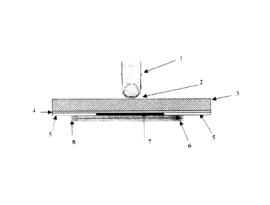
With reference to the drawing, a capacitive touch switch according to the
invention comprises anon-conductive transparent cover 3, made for instance of
glass or plastic having a touch sensitive area 2 where the user's finger 1 may
touch it. Under the transparent cover 3, by means of a non-conductive
transparent adhesive 4, a transparent printed circuit board 5 is attached, on
which an opaque icon-shaped electrode 7 is placed. The icon-shaped electrode
7, made for instance of copper, has a dimension sufficient to allow the
capacitive
effect of the touch switch, and it is directly connected to the rest of the
electronic
circuit supported by the printed circuit board 5. The icon-shaped electrode 7
may
have whatever shape related to the different function or parameter that the
user
can choose by touching the switch. In figure 2a the icon-shaped electrode 7
has
the typical shape of an on/off button, while in figure 2b the shape of the
electrode
7 has the object to indicate a specific selection of a heater on a cooktop.
Under the transparent printed circuit board 5 a planar light guide 6 is placed
having an edge 6a where a light emitting diode (LED) 8 is placed for conveying
light to the light guide 6. The LED 8 is directly connected to the electronic
circuit
of the printed circuit board 5.
From the above description it is clear that the touch switch according to the
invention allow a cost reduction for the icon serigr,aphy, which is somehow
"embedded" in the single side printed circuit board. Moreover there is a cost
saving of transparent material and electrode assembly, for instance compared
to
a traditional ITO solution.
A dark effect on the surface of the control panel can be obtained when the
single
switch or the whole control panel is off. There is no need of using
transparent
electrodes, springs, conductive rubber pieces and holes in the printed circuit
4
CA 02640443 2008-10-06
board. The LED may have three different conditions of illumination level, i.e.
a
first "off' level when the switch and/or the overall control board is switched
off, a
second intermediate level in which the touch switch, or better the icon
thereof,
can be seen by the user but the touch switch is inactive (even if touched by
the
user, there is no effect on the appliance), and a third high level in which
the icon
is illuminated at the highest level in order to inform the user that the
specific
touch switch is active and can be used. A different level of illumination may
be
used for providing the user with an immediate feedback in order to inform him
that the function or parameter has been selected correctly.