Note: Descriptions are shown in the official language in which they were submitted.
CA 02640519 2008-07-28
WO 2007/096313
PCT/EP2007/051533
PLANAR HEAT PIPE FOR COOLING
The present invention relates to an apparatus of planar heat pipe
for cooling. It is applicable to, but not just limited to electronic devices,
for
example by embedding the planar heat pipe into a printed circuit board for
inherent cooling of heat-dissipating components.
As functionality and performance of semi-conductors continuously
increase, so is the amount of dissipated heat per unit of their surface area.
To control the rising temperature of printed circuit boards, referred to as
PCB
in the following description, a continuous improvement in cooling
performance is required, especially for high-density multi-layered PCB
assemblies featuring a high concentration of electronic components in small
volumes.
Heat pipes are able to deliver that high performance in a relatively
small form factor and in a fully passive mode, that is without a power source.
Traditional heat pipes are cylindrical, tubular sealed structures containing a
fluid and capillary grooves or pores on their inner surface. The heat
dissipated by an external source such as electronic components warms up
the fluid on one end of the pipe, where it vaporizes. Vapour flows towards the
other end of the pipe by pressure gradient effect where it cools down and
condenses, dissipating heat out of the structure. Condensed fluid circulates
back along the inner surface, lined with grooves or pores, towards the heated
end by capillary action. A PCB assembly equipped with such a heat pipe
based cooling system provides a high level of performance. The heat pipe is
approximately 3 times lighter than a solid copper structure with equivalent
dimensions and has approximately 3 times better thermal conductivity. For
example, this kind of heat pipe assembly is used in laptop computers to cool
the CPU.
However, integration of tubular heat pipes into PCB assemblies is
limited by the former's cylindrical structure versus the latter's planar
buildup.
Nowadays, planar heat pipes are also available, but they are still fabricated
as an individual item, based on the same kind of metalworking processes as
CA 02640519 2012-08-28
2
used for tubular heat pipes, like metal forming and various types of welding.
This requires dedicated, high-energy tooling and machinery that do not offer
a high level of flexibility. Some variants are even based on originally
cylindrical heat pipes, flattened to obtain an oval section which can be
arranged and bonded between two metal layers. This requires an even more
comprehensive array of manufacturing processes, none of which are part of
a regular PCB manufacturing process. Therefore, it may not be a really cost
effective solution.
In addition, the linear shape of tubular heat pipes does not allow
for a flexible layout of heat dissipating components onto the PCB. As a
consequence, the entire assembly of components and printing of circuits may
be strongly impacted by the cooling system.
In an attempt to better integrate a cooling system into a PCB,
planar heat pipes have been introduced in the past. Unfortunately they were
manufactured as individual items, based on processes very similar to those
used for tubular heat pipes described above. Therefore, these solutions may
not be cost effective either and may not offer a higher level of flexibility.
The present invention aims to provide an apparatus that may be
used to provide a cost effective and flexible solution to the problems
mentioned above while presenting similar thermal performances.
According to an aspect, the present invention provides a
planar heat pipe for cooling. In its most basic form, it includes two panels
that
are both metal clad on one side, at least one of the panels being grooved on
its metal clad side. The panels are assembled with their metal clad sides
oriented face-to-face to form a sealed cavity, which is partly filled with a
fluid.
The fluid circulates by capillary action along the grooves towards zones
exposed to heat where it vaporizes. Vapour may circulate back by pressure
gradient effect through the cavity towards zones not exposed to heat where it
condenses. In a mode of implementation, the heat pipe may be embedded in
a circuit board formed by the panels for inherent cooling of heat-dissipating
components.
CA 02640519 2012-08-28
3
For example, the plating metal may be copper and the panels may
be made from an organic material, a composite or a ceramic material.
The grooves may be etched or plated in/onto the metal clad
layers.
Sealing of the cavity may be ensured laterally by use of a low-
permeable crystalline material as an adhesive to assemble both panels or by
a metallized trench.
The fluid may simply be water or any other fluid commonly used in
heat pipes.
A septum-topped aperture in one of the panels may enable
evacuation of air and subsequent injection of the fluid into the cavity with a
syringe.
In another of its aspects, the present invention provides a circuit
board for cooling of heat-dissipating components. It includes two panels that
are both metal clad on one side, at least one of the panels being grooved on
its metal clad side. The panels are assembled by their metal clad sides to
form a sealed cavity. The cavity is partly filled with a fluid. The fluid
circulates
by capillary action along the grooves towards zones exposed to heat
conveyed in through the panels preferably by thermal vias and where fluid
vaporizes.
Vapour may circulate back by pressure gradient effect through the
cavity towards zones where heat is conveyed out through the panels
preferably by thermal vias and where vapour condenses.
The outer surfaces of the two panels may later be patterned with
printed wiring and assembled with electronic components, thus integrating
electronic and cooling functions into one product.
According to an aspect of the present invention there is provided a
circuit board for cooling of heat-dissipated components assembled thereon,
including at least two panels at least one of which is populated with heat-
dissipating components, both panels being metal clad on a side, at least
one of the panels being formed from a printed circuit board laminate and
comprising a plurality of grooves on its metal clad side, the panels being
bonded together by an adhesive layer with their metal clad sides oriented
face to face so as to form a circuit board containing a sealed cavity having
a height defined by a thickness of the adhesive layer and the separation of
the metal clad sides, the cavity being partly filled with a fluid, the fluid
CA 02640519 2012-08-28
3a
circulating by capillary action along the grooves towards zones exposed to
heat where the fluid vaporizes.
Thus, key advantage provided by the present invention in any of
its aspects is that it is based on most standard processes of multilayer PCB
fabrication such as laminating, selective metal plating and etching.
Therefore,
it is a highly cost effective solution. Furthermore, the invention provides a
very flexible design solution enabling to adapt the cooling paths to the PCB
layout, especially to the higher heat dissipation locations. Not requiring any
supplementary materials, it is even considerably lighter than a tubular heat
CA 02640519 2008-07-28
WO 2007/096313
PCT/EP2007/051533
4
pipe based solution. Implemented as enhancement of a computer aided
engineering tool, heat pipe cooling cavities could be designed concurrently
with the layout of components placement and printing of circuits, ensuring
optimised thermal management. This enables multilayer PCB assemblies,
which are high density electronic devices, to benefit the most from the
integrated heatpipe cooling function.
A non-limiting example of the invention is described below with
reference to the accompanying drawings in which :
- figure 1 schematically illustrates an example of a printed circuit
board as an embodiment of the invention,
- figure 2 schematically focuses on grooves etched in a copper layer
of a PCB laminate according to the invention,
- figure 3 schematically focuses on a method to fill a heat pipe cavity
according to the invention with cooling fluid.
In the figures, like reference signs are assigned to like items.
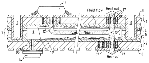
Figure 1 schematically illustrates an example of a printed circuit
board as an embodiment of the invention.
It includes a PCB metal-clad laminate 1 with metal layers 3 and 4
on each of its sides and a PCB metal-clad laminate 2 with metal layers 5 and
6 on each of its sides. In the example of the figure, clad metal is copper and
PCB laminates are made from an organic material, for example a glass-fibre
reinforced polymeric material such as the well-known FR-4. But alternative
dielectric materials could be used, ceramic materials for example, plated with
different metals in different thicknesses.
PCB laminates 1 and 2 are bonded all together excluding the heat
pipe areas through the use of an adhesive dielectric film 7. The thickness of
the adhesive film 7 forms a cavity 8. The height of cavity 8 may be adapted
by adding one ore more filler layers. Within the whole of the cavity 8,
parallel
grooves 9 are preferably etched in the copper layer 4 of PCB laminate 1 and
in the copper layer 5 of PCB laminate 2, prior to bonding laminates 1 and 2.
CA 02640519 2008-07-28
WO 2007/096313
PCT/EP2007/051533
The cavity 8 contains an underpressure and a fluid 10, for
example water. Air has been evacuated from- and water has been injected
into the cavity 8 through a septum 14 assembled on top of a metallized hole
drilled right through the PCB laminate 2. A septum is a device ensuring
5
hermeticity while enabling evacuation of air and introduction of a fluid with
a
syringe. Its use is described in detail in figure 3 below. To avoid loss of
cooling performance, the filling system should be located as far as possible
from any heat source. In any case, both layout of the cooling cavity 8 and
location of the hole 15 must be considered as part of the design phase of the
10 PCB,
concurrently with the assembly of components and printing of circuits.
Computer aided engineering tools could even manage complex constraints
resulting from multi-layered PCBs, which can stack up to 40 layers or more,
each layer including printed circuits. These tools would enable to design the
optimal cooling cavity for each PCB laminate. Possibly, a best cooling cavity
15 for a given PCB design may not follow a straight path and some of the
cavities may have to be filled by a hole running right through several PCB
laminates.
By capillary action, each groove is filled with water. The amount of
water injected must equal the volume of the combined grooves. Indeed, a
larger amount of water would prevent vapour from efficiently circulating in
the
cavity 8. In the example of the figure, a metallized trench 11 running right
around the sides of cavity 8 ensures lateral sealing of the cavity 8. The
trench
11 prevents fluid 10 from gradually permeating through the adhesive
dielectric film 7. Preferably, crystalline thermoplastic materials could also
be
used instead of the adhesive dielectric film 7, for example liquid crystalline
polymer well-known as LCP or syndiotactic polystyrene well-known as SPS.
Thanks to the extremely low permeability for moisture of these materials,
there would be no need for a metallized trench to laterally seal the cavity 8.
In operation, the component 13 dissipates heat through PCB
laminate 1, vaporizing water that is nested in the grooves in the vicinity of
the
component 13. As the laminate-itself is a relatively poor thermal conductor,
heat transportation through the PCB laminate 1 to the heat pipe structure is
assisted by use of so-called thermal vias 12. For example, the thermal vias
12 are holes in PCB laminate 1 that have been filled with metal. Vapour
moves towards the cooler side of the cavity 8 where pressure is lower
CA 02640519 2008-07-28
WO 2007/096313
PCT/EP2007/051533
6
because no heat is applied. There, vapour releases heat back into the PCB
and subsequently to the ambient environment or, for example, a heat sink
structure. Therefore it condenses. Heat transportation through the PCB
laminate 1 from the heat pipe structure is assisted by use of thermal vias 17,
for example holes in PCB laminates 1 and 2 filled with metal. At the same
time, emptied grooves that contained water that vaporized are replenished by
capillary action. On the one hand, the height of the heat pipe cavity 8 needs
to be kept as small as possible to keep the overall PCB thickness as thin as
possible. On the other hand, the cavity height needs to be large enough to
allow adequate vapour flow inside. In the example of the figure, the height of
the heat pipe cavity 8 is around 1 millimetre.
It is to be understood that variations to the example described in
figure 1, such as would be apparent to the skilled addressee, may be made
without departing from the scope of the present invention.
Figure 2 schematically focuses on grooves etched in a copper
layer of a PCB laminate according to the invention.
By a view in perspective, it zooms in on some of the parallel
grooves 9 etched in PCB laminate 2 of the preceding example. In the case
that thickness of the copper layer 5 was not to allow etching, a plating
process could possibly be considered instead of etching to form the grooves.
Capillary action enables water to easily circulate along the flat and parallel
grooves 9 from the condensation zone of the cavity 8 to its vaporization zone.
As sketched on the figure, fluid follows the course of the grooves, flowing in
their depths. Efficiency of capillary action depends on the width-height ratio
of
the grooves. In the example of the figure, the grooves are 80 microns high
and wide.
In the example of the figures, both PCB laminates 1 and 2 have
been grooved to enable capillary action. But only one could have been
grooved, thus requiring a smaller amount of cooling fluid and a smaller
vapour cavity, but also providing a less efficient cooling functionality.
It is to be understood that variations to the example described in
figure 2, such as would be apparent to the skilled addressee, may be made
without departing from the scope of the present invention.
CA 02640519 2008-07-28
WO 2007/096313
PCT/EP2007/051533
7
Figure 3 schematically focuses on a method to fill a heat pipe
cavity according to the invention with cooling fluid.
In the example of the figure, filling is performed by use of the
septum 14, which is a disc-shaped seal made from an elastomeric material,
typically silicone. It is encased in metal, apart from a small aperture to
allow
insertion of a syringe. This assembly is soldered onto the copper layer 3 of
the PCB laminate 1. The septum 14 is a key to a simple and workable
solution for filling and sealing the embedded heat pipe cavity 8 with a
syringe
16. In a first step, the hollowed needle of the syringe 16 is introduced
through
the septum 14 to conveniently establish internal vacuum in the cavity 8.
Vacuum facilitates later introduction of a fluid within the cavity 8 and
facilitates its vaporization. As the needle is removed, the elastomeric seal
of
the septum 14 re-establishes itself, thus providing airtightness. In a second
step, the hollowed needle of the syringe 16 is introduced through the septum
14 to inject water in the cavity 8. Once again, as the needle is removed the
elastomeric seal of the septum 14 provides immediate airtightness and fluid
sealing. For long-term hermeticity, the top of the septum 14 can be
permanently sealed by a drop of solder.
It is to be understood that variations to the example described in
figure 3, such as would be apparent to the skilled addressee, may be made
without departing from the scope of the present invention.