Note: Descriptions are shown in the official language in which they were submitted.
CA 02640565 2008-07-29
WO 2007/088321 PCT/GB2006/050456
- 1 -
Track Twist Monitoring
This invention relates to a method and to equipment
for monitoring railway tracks, in particular for
determining their twist over the full range of
wavelengths.
Track recording vehicles are known, which include
instruments for measuring many different attributes of a
railway track. One of the frequently measured properties
is track cant, which is the tilt of the track at a
particular point when compared to the horizontal plane.
Track twist is the difference of the track cant between
one point of measurement and another point along the
track. The distance between the two points is fixed
during the measurement and is called the base of the
twist. If the base is 3 m then the measured twist is
called 3 m twist.
Track twist can be measured directly using a rigid
frame (usually the body of a vehicle) and transducers
measuring the distance of the frame above the rails.
Track maintainers often use measurements of more than one
kind of twist to determine the quality of the track.
Instrumentation to provide direct measurements for all
these different twists is expensive.
Inertial track measurement systems can cost-
effectively measure track twist of any base from
measurement of track cant at successive positions along a
track. For example track cant may be measured with
sensors most of which are on the body of a track
recording vehicle. Typically the instrumentation involves
sensing as follows: the lateral acceleration A of the
body; the angular speed Gr of roll of the body (i.e.
turning about its longitudinal axis); the angular speed
CA 02640565 2008-07-29
WO 2007/088321 PCT/GB2006/050456
- 2 -
Gy of yaw of the body (i.e. turning about a vertical
axis). These transducers can measure the tilt of the
body. In addition there are sensors for the heights, on
each side, to measure the relative tilt between the body
and the rails. These heights can be measured directly,
using optical transducers; or using electronic
transducers in multiple stages, using sensors for the
distances on each side between the bogie and the body,
and sensors for the distances on each side between the
bogie and the axle, assuming that the tilt of the rigid
axle is the same as the tilt of the rails. There is also
a sensor of the displacement along the track (tachometer)
and a system clock. These two instruments are used to
regulate the sampling and calculate the vehicle speed.
Such instrumentation enables a full bandwidth cant signal
to be obtained, made up of short and long wavelengths
components, ie high and low frequency components.
However, this way of determining cant (and hence
twist) uses a number of components, whose measurement
errors add up during the processing, thus increasing the
uncertainty of the measured geometry data. The cant data
is assembled from long and short wavelength components.
The filtration procedure producing these two components
has inherent start-up transients, rendering the beginning
of the recorded data unreliable, and this unreliable
section can be several hundred metres long, depending on
filter design. The processing also involves integration
of the high frequency signal from the roll gyroscope.
Integration is a sensitive operation as the limited
accuracy of any system may render it unstable, especially
at low speeds. This is why a method of determining twist
would be desirable that:
1) used less transducers
2) needed no filtration
3) avoided the need for integration.
CA 02640565 2008-07-29
WO 2007/088321 PCT/GB2006/050456
- 3 -
According to the present invention there is provided
equipment for monitoring twist of railway tracks, the
equipment comprising a vehicle including a frame, and
sensors on the frame comprising a roll sensor to measure
the rate of roll about a longitudinal axis, and sensors
to monitor the variations in the relative tilt between
the frame and the rails, a sensor to monitor distance
travelled, means to sample data from the sensors, and
means to determine from the sampled data the twist of a
railway track.
The frame may comprise at least part of a vehicle
body, or at least part of a bogie of a vehicle. As in
the prior art system described above, height sensors may
be arranged to measure the variations in height between
the frame and axle boxes at each end of a wheelset.
Alternatively height sensors may be arranged to measure
the variations in height between the frame and the rails,
for example by a non-contact optical technique. The
difference of the height measurements on the opposite
sides can be used to calculate the relative tilt between
the frame and the rails.
The twist determining means requires values of time,
and this may be provided by a clock means. Such a clock
means may be used to control sampling, or alternatively
the sampling may be controlled in response to signals
from the sensor monitoring vehicle travel. This may
monitor the distance travelled along a track
(tachometer), or may monitor vehicle speed from which the
distance travelled can be deduced. The clock means may
form part of a computer for performing the calculations,
or may be a separate component.
The present invention also provides a method for
monitoring twist of railway tracks, the method using a
CA 02640565 2008-07-29
WO 2007/088321 PCT/GB2006/050456
- 4 -
vehicle with a frame, the method comprising measuring the
distance travelled by the vehicle, the changes in lateral
tilt of the frame between successive positions along the
track, subtracting therefrom measured changes in the tilt
of the frame relative to the rails, and so deducing the
change in cant, and from successive deduced changes in
cant determining the twist of the railway track.
The data may be sampled either at time intervals, or
at positions spaced along the track, that is to say the
data may be sampled in either the temporal or spatial
domain. The intervals between successive samples do not
have to be equal, but there are preferably several
samples per metre of vehicle travel along the track.
More preferably there are at least eight samples per
metre. The data may be digitized before being
subsequently processed. The measurements from the roll
rate sensor, combined with the time interval between one
measurement and the next, enable changes in lateral tilt
of the frame to be detected; this may be combined with
measurements of changes of tilt as determined from the
values of height, to determine the change of cant along a
length of track, and hence to determine the twist.
Such measurements avoid the need to filter or
integrate signals, and the results are consequently
stable, and measurements can be made at substantially any
desired speed. It will be appreciated that, unlike the
prior art, the present invention provides a way of
determining track twist directly using a system of the
inertial track recording type, rather than first
determining cant; the present invention determines values
of changes in cant, rather than determining absolute
values of cant.
Preferably the equipment also includes a position
CA 02640565 2008-07-29
WO 2007/088321 PCT/GB2006/050456
- 5 -
locating instrument arranged to provide position
information, and may also include automatic means for
transferring data to a base station remotely and at
intervals.
Such equipment can be installed on a bogie of a
service vehicle, for example a passenger coach, without
causing inconvenience to passengers or staff. Operations
may be totally automatic, so no staff are required to
monitor it, and are not affected by changes in vehicle
speed or by the vehicle stopping. Consequently the
equipment enables the track along which that service
vehicle travels to be monitored for twist on every
journey, so the track twist may be monitored several
times a day. Because it is installed in a service
vehicle, no additional vehicle operating costs are
incurred in performing the monitoring. Alternatively the
equipment may be installed in a dedicated track
monitoring vehicle, and the data obtained may be stored
on board the vehicle.
The position locating instrument might use GPS.
More precise information on position may be obtained
using differential GPS, or by detecting the location of
objects at known positions along or adjacent to the track
such as points or crossings. Dead reckoning methods may
also be used, including inertial guidance systems, and
measuring distance from known positions.
The invention will now be further and more
particularly described, by way of example only, and with
reference to the accompanying drawings, in which:
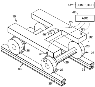
Figure 1 shows a diagrammatic perspective view of
the bogie of a vehicle incorporating a track twist
monitoring system; and
CA 02640565 2008-07-29
WO 2007/088321 PCT/GB2006/050456
- 6 -
Figure 2 shows graphically the results of
experimental measurements of track twist using the system
of figure 1.
Referring to figure 1, a track monitoring vehicle 10
includes bogies 24 (only one of which is shown). The
bogie 24 includes an H-frame 25 and two wheelsets 27 each
comprising two wheels 28 integral with an axle 29. At
each end the axle 29 locates in a bearing in an axle box
(not shown), the axle box being connected by springs (not
shown) to the frame 25 so that the axle 29 and the axle
box can undergo limited movement relative to the frame
25; these features are conventional. The wheels 28 roll
along the rails 35 of a railway track 36.
The vehicle 10 also incorporates linear displacement
transducers 38 at each side of the bogie 24, above the
ends of one of the wheelsets 27. Each linear
displacement transducer 38 is connected between the frame
and the axle box associated with that wheelset 27, so
as to measure any vertical displacement, Dl or D2, of the
wheel 28 relative to the frame 25. Mounted at the middle
of the frame 25 is an angular velocity roll sensor 40,
25 such as a gyro sensor, providing signals representing the
angular velocity w. The signals from the two transducers
38 and from the roll sensor 40 are provided via an ADC
(analogue-to-digital converter) 42 to a computer 44 on
the vehicle 10, represented diagrammatically.
The signals from the transducers 38 and from the
roll sensor 40 are sampled at frequent intervals. They
may, for example, be sampled at regular intervals of say
2.5 msec (if the vehicle is travelling fast), or at
regular intervals of say 10 msec if the vehicle 10 is
travelling slowly (say no more than 36 km/hr); or
CA 02640565 2008-07-29
WO 2007/088321 PCT/GB2006/050456
- 7 -
alternatively, the signals may be sampled at regular
distances along the track, say every 0.1 m. In the
following explanation it will be taken that the interval
between successive samples is At, but it should be
appreciated that these successive intervals are not
necessarily equal to each other.
Between one and sample and the next, the angular
change of the tilt (0) of the frame 25 (referred to above
as the lateral tilt, and referring to the tilt in an
absolute frame of reference), can be calculated from:
AO =wOt
where w is the angular velocity of roll, as deduced from
the signals from the sensor 40. (The value of w used in
this equation may be either the value at the start of the
interval, or that at the end of the interval, or
alternatively might be the average of the values sampled
at the beginning and the end of this interval.)
To determine the changes in cant it is necessary to
take into account the fact that the frame 25 may be
tilted relative to the track 36. From the sampled
measurements from the sensors 38 at an instant of time
the corresponding angle of tilt of the frame 25 relative
to the track 36 can be calculated from:
a = (D2 - D1) /L
where L is the separation between the two rails 35.
Between one data sample and the next this angle of tilt a
changes by Da, which can be deduced from the successive
calculated values of a.
CA 02640565 2008-07-29
WO 2007/088321 PCT/GB2006/050456
- 8 -
Hence the change in cant, Ac, of the track 36
between one sample and the next is given by:
Oc = w Ot - Da
The twist, Tw, of the track 36 can hence be deduced by
adding the successive calculated values of Ac over an
appropriate length of track, for example 3 m.
Tw =Y- Ac or Tw' = L(Y- Ac)
The number of the samples used for the summation is
fixed in case of spatial sampling and variable if
temporal sampling is used. The actual result does not
depend on the method chosen, provided that the temporal
sampling is frequent enough to yield a sample close
enough to the end of the base, in our example 3 m.
It will be appreciated that the equations given
above assume consistent units for all the parameters, for
example SI units, and that the values of change of cant
(Ac), and those of twist (Tw), are consequently given in
radians. If the value of twist is to be given in mm, it
is merely necessary to multiply the twist (Tw) in radians
by the track width (L) in mm, as indicated in the
equation for Tw' above. Preferably these summations are
carried out on a rolling set of data, so that the twist
is determined at every sample point (for the previous 3 m
of track).
It has been found that it is sufficient to obtain
eight data samples per m of travel along the track 36.
It will be appreciated that the above calculation
1) does not involve any data filtration, so the
results are available right after the travelled
CA 02640565 2008-07-29
WO 2007/088321 PCT/GB2006/050456
- 9 -
distance of the twist base (3 m in the example),
substantially in real-time
2) does not involve any data integration, so the
result calculated is stable, and the measurements
can be taken at substantially any speed of the
vehicle 10,
3) is subject only to the resolution of the
transducers 38 and 40, and any limits imposed by
the ADC 42.
Since the results are available in real time, the
invention can be used to control a marking system, such
as a paint-spraying device, to mark locations of
excessive twist values. The on-site marks help the track
maintainers find the locations where twist faults have to
be eliminated.
Referring out to figure 2, experimental measurements
of 3 m twist along a 100 m section of track are shown as
obtained using the instrumentation described above. One
set of measurements are shown in a solid line, and a
repeat set of measurements are shown with a broken line.
The solid line was measured starting the vehicle and
operation of the instrumentation at the start of the
section, while the broken line was measured starting the
vehicle (and the instrumentation) from an earlier point.
No meaningful measurements of twist can be calculated
over the first 3 m of operation; however, beyond this
distance the solid line immediately matches the broken
trace. It will be seen that the values of the twist are
substantially consistent, and that along this section of
track the twist does not exceed 2.5 mm in magnitude at
any point. This is an excellent result from an inertial
system optimized to operate at 125 mph. Further
optimization for measuring at low speeds can eliminate
any significant differences between recordings.