Note: Descriptions are shown in the official language in which they were submitted.
CA 02640829 2008-10-09
EXTENDED LIFE LED FIXTURE
FIELD OF THE INVENTION
[0001] The invention relates generally to light emitting diode (LED) based
lighting fixtures,
and more particularly to fixtures using multiple LED drivers and multiple LED
lamps or
multi-chip LED packages to provide an extended life fixture.
BACKGROUND
[0002] LEDs have become a popular choice for light fixtures due to their
relatively
inexpensive cost, low voltage requirements, compact size, and longer operating
lifetime. The
operating lifetime of an LED fixture is limited in part due to the decrease in
output light
intensity of the LEDs over time. This decrease or lumen depreciation is
affected by
temperature so even though the brightness of the LEDs can be increased by
increasing the
electrical current supplied to the LEDs, the increased current increases the
temperature of the
LEDs, which in turn reduces the efficiency and lifetime of the LEDs.
[0003] Conventional LED light fixtures consist of a single driver and a single
LED board or
lamp, so once the driver fails or the light intensity decreases substantially,
the light fixture
must be replaced. For some applications, such as highway signage, street
lighting on busy
highways, and lighting in hazardous areas, replacement is difficult due to the
position or
location of the fixture. For other applications replacement is difficult due
to the disruption
associated with the replacement, such as having to stop or pause a production
or
manufacturing line or having to limit access to an area.
SUMMARY OF THE INVENTION
[0004] It is therefore an object of the present invention to extend the
lifetime of LED light
fixtures and reduce LED replacement activity costs. The present invention uses
multiple
drivers and multiple LED lamps or multi-chip LED packages so that the lifetime
of the
fixture is multiples of the lifetime of a conventional fixture. For example,
rather than a light
fixture with 10 LEDs and one LED driver, the present invention provides a
light fixture with
20 LEDs and two LED drivers or a light fixture with 30 LEDs and three drivers,
where each
CA 02640829 2008-10-09
Page 2 of 30
driver drives ten LEDs. When the first LED driver or LED lamp has been
operating for a
predetermined time or its operating parameters are out of range, the first LED
driver and
lamp are deactivated and the second LED driver and lamp are activated. This
process
continues until all of the drivers have been activated. In this manner the
expected lifetime of
the light fixture is increased two or three times. For example, if a fixture
with a single LED
driver uses LEDs with a rated lifetime of 50,000 hours, then the lifetime can
be increased
from 50,000 hours to 100,000 hours by using two LED drivers and two LED lamps
(or an
appropriate number of multi-chip LED packages) or to 150,000 hours by using
three LED
drivers and three LED lamp (or an appropriate number of multi-chip LED
packages).
100051 According to one aspect of the invention, a single light fixture or
luminaire includes
multiple LED lamps or LED boards, multiple LED drivers, and a central
controller, where
each LED lamp is connected to a distinct LED driver and the central controller
is connected
to each of the LED drivers. The central controller activates the first LED
driver to drive the
first LED lamp. The central controller then monitors the first LED driver
until an operating
parameter satisfies a predetermined value. The predetermined value is based on
operating
factors, such as expected or actual lifetime of the LED driver or LED lamp or
expected or
actual degradation in performance of the LED driver or LED lamp. Once the
monitored
operating parameter of the first LED driver satisfies the predetermined value,
the central
controller deactivates the first LED driver which deactivates the first LED
lamp and activates
the second LED driver which drives the second LED lamp. The controller
monitors and
controls the second and any remaining LED drivers in a manner similar to the
first LED
driver and lamp.
[00061 Although some LEDs could be expected to operate well beyond their
claimed rating
(e.g. 50,000 hours), it is generally acknowledged that their lamp lumen
depreciation is too
high for operation beyond this rating point. In one aspect of the invention a
multi-lamp LED
driver concurrently drives multiple depreciated LED lamps to provide a light
level that
approximates the initial light level. Once all of the LED drivers have been
activated, the
conti-oller activates the multi-lamp LED driver which drives two or more of
the LED lamps
that were previously driven by the LED drivers. The multi-lamp LED driver may
drive the
CA 02640829 2008-10-09
Page 3 of 30
LEI) lamps at the same level as the LED drivers or at a different level
depending upon the
lumen depreciation characteristics of the LED lamps.
[0007] According to another aspect of the invention, the controller function
is distributed
between the LED drivers. The single light fixture includes multiple LED lamps
and multiple
LEI) drivers and each LED driver includes a controller. The controller can be
integrated
with the LED driver or can be provided by a; separate device that is connected
to the LED
driver.
[0008] The controller of the first LED driver activates the first LED driver
to drive the first
LEI) lamp. The controller of the first LED driver monitors an operating
parameter of the
first LED driver until the operating parameter satisfies a predetermined
value. Once the
moriitored operating parameter of the first LED driver satisfies the
predetermined value, the
controller of the first LED driver deactivates the first LED driver which
deactivates the first
LEI) lamp and activates the second LED driver so that it drives the second LED
lamp. The
cont.roller of the second and any remaining LED drivers operates in a similar
manner to the
controller of the first LED driver.
[0009] In another aspect of the invention a multi-lamp LED driver concurrently
drives
multiple depreciated LED lamps to provide a light level that approximates the
initial light
level. Once all of the LED drivers have been activated, the controller
associated with the last
LEI) driver to be activated, activates the multi-lamp LED driver which drives
two or more of
the LED lamps that were previously driven by the LED drivers. The multi-lamp
LED driver
may drive the LED lamps at the same level as the LED drivers or at a different
level
depending upon the lumen depreciation characteristics of the LED lamps.
[0010] The present invention can operate with multi-chip LED packages instead
of LED
lamps. Different LED drivers drive different subsets of LEDs within a package.
For
example, if there are four chips within a package, then a first LED driver
drives two of the
chips and a second LED driver drives the remaining two chips.
[0011] According to one aspect of the invention, a single light fixture
includes multiple LED
drivers, at least one multi-chip LED package, and a central controller, where
each LED
driver is connected to a distinct subset of LEDs and the central controller is
connected to
CA 02640829 2008-10-09
Page 4 of 30
each of the LED drivers. The central controller activates the first LED driver
to drive the
first subset of LEDs. The central controller then monitors the first LED
driver until an
operating parameter satisfies a predetermined value. The predetermined value
is based on
operating factors, such as expected or actual lifetime of the LED driver or
LEDs or expected
or actual degradation in performance of the LED driver or LEDs. Once the
monitored
opei-ating parameter of the first LED driver satisfies the predetermined
value, the central
controller deactivates the first LED driver which deactivates the first subset
of LEDs and
activates the second LED driver which drives the second subset of LEDs. The
controller
monitors and controls the second and any remaining LED drivers in a manner
similar to the
first LED driver and first subset of LEDs.
[001.2] In another aspect of the invention a multi-chip LED driver
concurrently drives
multiple depreciated subsets of LEDs to provide a light level that
approximates the initial
light level. Once all of the LED drivers have been activated, the controller
activates the
multi-chip LED driver which drives two or more of the subsets of LEDs that
were previously
driven by the LED drivers. The multi-chip LED driver may drive the subsets of
LEDs at the
same level as the LED drivers or at a different level depending upon the lumen
depreciation
characteristics of the LEDs.
[0013] According to another aspect of the invention, the controller function
is distributed
between the LED drivers. The single light fixture includes at least one multi-
chip LED
package and multiple LED drivers, where each LED driver includes a controller
and each of
the LED drivers drives a distinct subset of LEDs. The controller can be
integrated with the
LED driver or can be provided by a separate device that is connected to the
LED driver.
[0014] The controller of the first LED driver activates the first LED driver
to drive the first
subset of LEDs. The controller of the first LED driver monitors an operating
parameter of
the first LED driver until the operating parameter satisfies a predetermined
value. Once the
monitored operating parameter of the first LED driver satisfies the
predetermined value, the
controller of the first LED driver deactivates the first LED driver which
deactivates the first
subset of LEDs and activates the second LED driver so that it drives the
second subset of
CA 02640829 2008-10-09
Page 5 of 30
LEDs. The controller of the second and any remaining LED drivers operates in a
similar
manner to the controller of the first LED driver.
[0015] In another aspect of the invention a multi-chip LED driver concurrently
drives
multiple depreciated subsets of LEDs to provide a light level that
approximates the initial
light level. Once all of the LED drivers have been activated, the controller
associated with
the last LED driver to be activated, activates the multi-chip LED driver which
drives two or
more subsets of LEDs that were previously driven by the LED drivers. The multi-
chip LED
driver may drive the subsets of LEDs at the same level as the LED drivers or
at a different
level depending upon the lumen depreciation characteristics of the LEDs.
[00161 Other features, advantages, and objects of the present invention will
be apparent to
those skilled in the art with reference to the remaining text and drawings of
this application.
BRIEF DESCRIPTION OF THE DRAWINGS
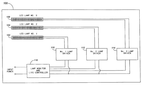
[0017] FIG. I illustrates a single light fixture with multiple LED drivers,
multiple LED
lamps, and a central controller according to one embodiment of the invention.
[0018] FIG. 2 illustrates a single light fixture with multiple LED drivers, a
multi-lamp LED
driver, multiple LED lamps, and a central controller according to one
embodiment of the
invention.
100191 FIG. 3 illustrates a single light fixture with multiple LED drivers and
controllers and
multiple LED lamps according to one embodiment of the invention.
[0020] FIG. 4 illustrates a single light fixture with multiple LED drivers and
controllers, a
multi-lamp LED driver and controller, and multiple LED lamps according to one
embodiment of the invention;.
[0021] FIG. 5 illustrates a single light fixture with multiple LED drivers,
multiple multi-chip
LEI) packages, and a central controller LED chips according to one embodiment
of the
invention.
[0022] FIG. 6 illustrates a single light fixture with multiple LED drivers, a
multi-chip LED
driver, multiple multi-chip LED packages. and a central controller according
to one
embodiment of the invention.
CA 02640829 2008-10-09
Page 6 of 30
100231 FIG. 7 illustrates a single light fixture with multiple LED drivers and
controller and
mull:iple multi-chip LED packages according to one embodiment of the
invention..
[0024] FIG. 8 illustrates a single light fixture with multiple LED drivers and
controllers, a
multi-chip LED driver and controller, and multiple multi-chip LED packages
according to
one embodiment of the invention.
[00251 FIG. 9 illustrates an exemplary method of operation of a single light
fixture according
to one embodiment of the present invention.
[0026] FIG. 10 illustrates an exemplary method of operation of a single light
fixture
according to another embodiment of the present invention.
DETAILED DESCRIPTION
[0027] The present invention provides an extended life LED fixtures. Briefly
described, a
single fixture includes multiple drivers and multiple LED lamps or multi-chip
LED packages
so that a single light fixture provides multiples of a conventional fixture's
lifetime. A
controller, which can either be centralized or distributed, activates and
deactivates the LED
drivers so that the different LED lamps or subsets of LEDs are driven
sequentially. Some
embodiments include a multi-lamp LED driver or a multi-chip LED driver to
concurrently
drive multiple LED lamps or multiple subsets of LEDs that have previously been
driven by
the LED drivers.
Multiple LED Lamps and Multiple LED Drivers
[0028] FIGs. 1-4 illustrate light fixtures that use LED lamps or LED boards.
Each LED lamp
includes a number of LEDs that are driven as a single unit.
Centralized Control
[0029] FIG. I illustrates one embodiment of the present invention where a
single light fixture
or luminaire 100 includes three LED lamps 102, 104 and 106, three LED drivers,
110, 112
and 114, and a central controller 116. Each LED lamp 102, 104 and 106 is
connected to a
distinct LED driver 110, 112 and 114, respectively, and the central controller
116 is
CA 02640829 2008-10-09
Page 7 of 30
connected to each of the LED drivers. Each LED lamp (e.g. 102) illustrated by
FIG. 1
incliides 20 LEDs. Although the number of LEDs in each LED lamp may vary, each
LED
lamp typically includes the same number of LEDs. An LED driver (such as LED
drivers
110, 112 and 114) provides the function of a conventional LED driver that
activates/powers
(i.e., turn on/off) the associated LED lamp.
[0030] The central controller 116 activates the first LED driver 110 to drive
the first LED
lamp 102. The central controller 116 then monitors the first LED driver 110
until one or
more operating parameters satisfy certain predetermined values. The
predetermined values
are based on one or more operating factors, such as expected or actual
lifetime of the LED
driver or LED lamp or expected or actual degradation in performance of the LED
driver or
LED lamp. Once the monitored operating parameter of the first LED driver 110
satisfies the
predetermined value, the central controller 116 deactivates the first LED
driver 110 which
deactivates the first LED lamp 102.
[0031] If the operating parameter is based on time, such as an expected or
rated lifetime or
expected or rated lumen depreciation, then the central controller includes a
timer function to
keep track of the time that the LED drivers and lamps are activated. If the
operating
parameter is based on an actual output of the LED drivers or LED lamps, then
the central
controller includes an input from the LED drivers or lamps that corresponds to
the monitored
para:meter or an input from a sensor that senses the monitored parameter. In
some
embodiments, the operating parameter corresponds to the current, voltage or
power drawn by
the LED lamp. In other embodiments, the operating parameter corresponds to the
amount of
light being output.
[0032] Once the first LED driver is deactivated, the central controller 116
activates and
monitors the second LED driver 112 which drives the second LED lamp 104. Once
the
second LED driver satisfies the predetermined value, the central controller
116 deactivates
the second LED driver 112 which deactivates the second LED lamp 104. The
central
controller 116 then activates the third LED driver 114 that drives the third
LED lamp 106. In
one embodiment, the central controller monitors the third LED driver 114 and
once the
predetermined value is met the central controller 116 deactivates the third
LED driver 114
CA 02640829 2008-10-09
Page 8 of 30
which deactivates the third LED lamp 106. In another embodiment, the central
controller
does not monitor the third LED driver and allows it to operate until it fails
or is replaced. By
using multiple LED drivers and multiple LED lamps the time between
replacements is
significantly longer than with a conventional fixture with a single LED lamp
and driver. In
the embodiment illustrated by FIG. 1, the time between replacements is
approximately three
times longer than with a conventional fixture that uses a single LED lamp and
driver.
[0033] FIG. 1 illustrates that the central controller is connected to the
power input to the
fixture. In this embodiment, the central controller gates the power to the LED
drivers to
activate and deactivate the LED drivers. As will be apparent to those skilled
in the art, other
metliods of activating and deactivating the LED drivers can be used,
including, but not
limited to having the central controller generate an enable signal to each of
the LED drivers.
Although Fig. 1 illustrates that the central controller is physically
connected to the LED
drivers, other embodiments may use wireless communication between the central
controller
and the LED drivers.
Centralized Control with Multi-Lamp LED Driver
[0034] FIG. 2 illustrates another embodiment of a multiple driver, multiple
lamp fixture that
differs from the embodiment illustrated by FIG. 1 by the addition of a multi-
lamp LED
driver. The single light fixture 100 includes three LED lamps 102, 104 and
106, three LED
drivers 110, 112 and 114, a multi-lamp LED driver 124, and a central
controller 116. The
components of the light fixture are connected in a manner similar to that
described above in
connection with FIG. 1. The multi-lamp LED driver 124 is connected to the
central
controller 116 and LED lamps 102, 104 and 106.
[0035] The operation of the light fixture illustrated by FIG. 2 is essentially
the same as FIG.
1 for the activation and deactivation of the first LED driver and lamp, the
second LED driver
and lamp, and the third LED driver and lamp. Once the operating parameter of
the third
LED driver 114 satisfies the predetermined value, the central controller 116
deactivates the
third LED driver which deactivates the third LED lamp and activates the multi-
lamp LED
driver which concurrently activates the first, second and third LED lamps. In
some
CA 02640829 2008-10-09
Page 9 of 30
embodiments, the central controller monitors the operating parameters of the
multi-lamp
LED driver and deactivates the multi-lamp LED driver when the operating
parameter
satisfies a predetermined value. In other embodiments, the central controller
does not
monitor the multi-lamp LED driver.
[0036] As discussed above, the operating parameter can correspond to time,
such as the
expected lifetime of the LED driver, expected lifetime of the LED lamps,
andlor an expected
lumen depreciation of the LED lamps. If the predetermined value of the
operating parameter
is selected based on an expected lifetime of the LED driver and the LED lamps
have a longer
lifetime, then the embodiment illustrated by FIG. 2 can be used to drive the
LED lamps past
the life of their corresponding LED drivers. Driving multiple LED lamps that
have
experienced some lumen deficiency concurrently with the multi-lamp LED driver
produces
light at a level approximating the initial level. For example, if the expected
or rated lifetime
of an LED driver is 50,000 hours and the lumen depreciation of the LED lamps
is 70% after
50,000 hours, then driving three LED lamps having 30% of their initial light
levels
concurrently produces 90% of the initial light level.
[0037] The multi-lamp LED driver can drive the LED lamps at the same level
(e.g., same
current) as the LED drivers or at a different level. For example, if the
expected or rated
lifetime of an LED driver is 50,000 hours and the lumen depreciation of the
LED lamps is
50% after 50,000 hours, then driving three LED lamps having 50% of their
initial light levels
concurrently at 70% of the initial current level produces approximately 100%
of the initial
light level.
[0038] FIG. 2 illustrates that the multi-lamp LED driver drives all of the LED
lamps within
the light fixture concurrently. Depending upon the expected lifetime of the
LED drivers and
the expected lumen depreciation of the LED lamps, in other embodiments the
multi-lamp
LED driver drives less than all of the LED lamps. For example, if the expected
or rated
lifetime of an LED driver is 50,000 hours and the lumen depreciation of the
LED lamps is
50% after 50,000 hours, then.driving two LED lamps having 50% of their initial
light levels
concurrently produces 100% of the initial light level with only two of the
three LED lamps.
CA 02640829 2008-10-09
Page 10 of 30
Alte:rnatively, the light fixture can include a fourth LED lamp and associated
driver and a
second multi-lamp LED driver can drive the remaining two LED lamps.
[0039] FIG. 2 illustrates that the central controller is connected to the
power input into the
fixture. In this embodiment, the central controller gates the power to the LED
drivers and the
multi-lamp LED driver to activate and deactivate the LED drivers and the multi-
lamp LED
driver. As described in connection with FIG 1 above, other methods of
activating and
deactivating the LED drivers and multi-lamp LED driver can be used.
Distributed Control
[0040] FIG. 3 illustrates another embodiment of the present invention that
differs from the
embodiment illustrated by FIG. 1 in that the controller function is
distributed among the LED
drivers. The single light fixture 100 includes three LED lamps 102, 104 and
106, and three
LED drivers 118, 120 and 122. Each LED driver 118, 120 and 122 includes a
controller and
is connected to at least one other LED driver (i.e., 118 is connected to 120,
120 is connected
to 118 and 122, and 122 is connected to 120). The controller function can be
integrated with
the LED driver or can be provided by a separate device that is connected to
the LED driver.
[0041] The controller of the first LED driver activates the first LED driver
118 to drive the
first LED lamp 102. The controller of the first LED driver 118 monitors one or
more
operating parameters of the first LED driver 118 until the operating
parameters satisfy
predetermined values. Once the monitored operating parameter of the first LED
driver 118
satisfies the predetermined value, the controller of the first LED driver 118
deactivates the
first LED driver 118 which deactivates the first LED lamp 102 and activates
the second LED
drive;r 120 so that it drives the second LED lamp 104.
[0042] The controller of the second LED driver 120 monitors one or more
operating
parameters of the second LED driver 120. Once the operating parameter
satisfies a
predetermined value, the controller deactivates the second LED driver 120
which deactivates
the second LED lamp 104 and activates the third LED driver 122. In some
embodiments, the
controller of the third LED driver 122 monitors the third LED driver 122. Once
the
operating parameter satisfies the predetermined criteria, the controller of
the third LED
CA 02640829 2008-10-09
Page 11 of 30
driver 122, deactivates the third LED driver 122 which deactivates the third
LED lamp 106.
In ot:her embodiments, the third LED driver does not include a controller and
the third LED
driver and lamp are operated until they fail or are replaced.
[0043] FIG. 3 illustrates that the power input to the fixture is fed into the
first LED
controller. In this embodiment, the first LED controller gates the power to
the. first LED
driver to activate and deactivate the first LED driver and gates the power to
the second LED
controller. The second LED controller gates the power to the second LED driver
to activate
and deactivate the second LED driver and gates the power to the third LED
controller. The
third LED controller gates the power to the third LED driver to activate and
deactivate the
third LED driver. As will be apparent to those skilled in the art, other
methods of activating
and deactivating the LED drivers can be used, including methods using wireless
communication between the LED controllers.
Distributed Control with Multi-Lamp LED Driver
100441 FIG. 4 illustrates another embodiment of the present invention that
differs from the
embodiment illustrated by FIG. 3 by the addition of a multi-lamp LED driver
and controller.
The single light fixture 100 includes three LED lamps 102, 104 and 106, three
LED drivers
118, 120 and 122. Each LED driver 118, 120 and 122 includes a controller and
is connected
to at least one other LED driver (i.e., 118 is connected to 120, 120 is
connected to 118 and
122, and 122 is connected to 120). The third LED driver also is connected to a
multi-lamp
LED driver and controller 126 which is connected to the first, second and
third LED lamps.
100451 The operation of the light fixture illustrated by FIG. 4 is essentially
the same as FIG.
3 for the activation and deactivation of the first LED driver and lamp, the
second LED driver
and lamp, and the third LED driver and lamp. Once the operating parameter of
the third
LED driver 114 satisfies the predetermined value, the third LED controller
deactivates the
third LED lamp and activates the multi-lamp LED driver which activates the
first, second
and third LED lamps.
CA 02640829 2008-10-09
Page 12 of 30
[0046] Although FIG. 4 illustrates that the multi-lamp LED driver drives all
of the LED
lamps in the fixture, in other embodiments, as discussed above in connection
with FIG. 2, the
multi-lamp LED driver may drive less than all of the LED lamps.
[0047] FIG. 4 illustrates that the power input to the fixture is fed into the
first LED
controller. In this embodiment, the first LED controller gates the power to
the first LED
driver to activate and deactivate the first LED driver and gates the power to
the second LED
controller. The second LED controller gates the power to the second LED driver
to activate
and deactivate the second LED driver and gates the power to the third LED
controller. The
third LED controller gates the power to the third LED driver to activate and
deactivate the
third LED driver and gates the power to the multi-lamp LED driver. The multi-
lamp LED
controller gates the power to the multi-lamp LED driver. As will be apparent
to those skilled
in the art, other methods of activating and deactivating the LED drivers can
be used,
including wireless communication between the LED controllers.
Multiple Multi-Chip LED Packages and Multiple LED Drivers
[0048] FIGs. 1-4 illustrate light fixtures that use LED lamps. Alternatively,
multi-chip LED
packages can be used. A multi-chip LED package has at least two LED chips
within the
same package. The LED chips can be driven independently (i.e., each chip is
connected to a
different driver) or in subsets (e.g. two or more chips are connected to the
same driver). In
some embodiments the LED lamps illustrated by FIGs. 1-4 are simply replaced by
the
appropriate number of multi-chip LED packages. In other embodiments, different
drivers are
used to drive different chips within the multi-chip LED package. The use of
multi-chip LED
packages rather than single chip LED lamps permit a more compact design due to
the smaller
luminaire optical package and may provide a more cost effective solution due
to the lower
packaging cost of the chips.
Centralized Control
[0049] FIG. 5 illustrates an embodiment using multi-chip LED packages where
different
drivers drive different chips within the package. The single light fixture 100
includes a first
CA 02640829 2008-10-09
Page 13 of 30
LED driver 130, a second LED driver 132, a central controller 116, and five
multi-chip LED
packages 148a, 148b, 148c, 148d, 148e with each multi-chip package containing
four LED
chips e.g., 140a, 142a, 144a, 146a. The central controller is connected to the
first LED driver
and the second LED driver. The first LED driver is connected to two of the
four LED_ chips,
e.g., 144a, 146a, within each of the multi-chip LED packages and the second
LED driver is
connected to the remaining two LED chips e.g., 140a, 142a, within the multi-
chip LED
packages.
[0050] The operation of the light fixture illustrated by FIG. 5 is similar to
that described
above in connection with FIG. 1 except that instead of the first LED driver
and the second
LED driver driving separate LED lamps, the drivers drive different chips
within the multi-
chip LED packages. The central controller 116 activates the first LED driver
130 to drive a
first subset of LED chips in each multi-chip LED package 144a, 146a, 144b,
146b, 144c,
146c:, 144d, 146d, 144e, 146e. The central controller 116 monitors the first
LED driver until
one or more operating parameters satisfy certain predeterniined criteria or
values. The
predetermined values are based on the same type of factors described above in
connection
with the embodiments that use LED lamps. Once the monitored operating
parameter of the
first LED driver 130 satisfies the predetermined value, the central controller
116 deactivates
the first LED driver 130 which deactivates the first subset of LED chips. The
central
controller then activates the second LED driver 132 to drive the second subset
of LED chips
in each multi-chip LED package 140a, 142a, 140b, 142b, 140c, 142c, 140d, 142d,
140e,
142e. In some embodiments, the central controller monitors the second LED
driver and once
the predetermined value is met the central controller deactivates the second
LED driver 132
which deactivates the second subset of LED chips. In other embodiments, the
central
controller does not monitor the second LED driver and allows it to operate
until it fails or is
replaced.
[00511 FIG. 5 illustrates that the central controller is connected to the
power input into the
fixture. In this embodiment, the central controller gates the power to the LED
drivers to
activate and deactivate the LED drivers. As described in connection with FIG.
1 above,
other methods of activating and deactivating the LED drivers can be used.
CA 02640829 2008-10-09
Page 14 of 30
Centralized Control with Multi-chip LED Driver
[00521 FIG. 6 illustrates an embodiment of the present invention that differs
from the
embodiment illustrated by FIG. 5 by the addition of a multi-chip LED driver.
The single
light fixture 100 includes five multi-chip LED packages 148a, 148b, 148c,
148d, 148e (only
148e is shown in detail), two LED drivers 130, 132, a multi-chip LED driver
134 and a
central controller 116. The components of the light fixture are connected in a
manner similar
to that described above in connection with FIG. 5. The multi-chip LED driver
134 is
conriected to the central controller 116 and to all of the LED chips in all of
the multi-chip
LED packages.
[0053] The operation of the light fixture illustrated by FIG. 6 is similar to
that described
above in connection with FIG. 5 for the activation and deactivation of the
first LED driver
and the second LED driver. Once the operating parameter of the second LED
driver satisfies
the predetermined value, the central controller deactivates the second LED
driver which
deactivates the second subset of LED chips and activates the multi-chip LED
driver which
activates all of the LED chips in all of the LED packages. In some
embodiments, the central
controller monitors the multi-chip LED driver and once the predetermined value
is met the
centi-al controller deactivates the multi-chip LED driver which deactivates
all of the LED
chips. In other embodiments, the central controller does not monitor the multi-
chip LED
driver.
[0054] The multi-chip LED driver illustrated by FIG. 6 is connected to all of
the chips within
all of the multi-chip LED packages. Similar to the multi-lamp LED driver of
FIG. 2, the
multi-chip LED driver can be connected to less than all of the LED chips in
the multi-chip
LED packages. For example, the multi-chip LED driver could be connected to
less than all
of the LED chips within the multi-chip LED packages or could be connected to
less than all
of the multi-chip LED package.s.
[0055] FIG. 6 illustrates that the central controller is connected to the
power input into the
fixture. In this embodiment, the central controller gates the power to the LED
drivers and the
multi-chip LED driver to activate and deactivate the LED drivers and the multi-
chip LED
CA 02640829 2008-10-09
Page 15 of 30
driver. As described in connection with FIG. 1 above, other methods of
activating and
deactivating the LED drivers and multi-chip LED driver can be used, including
wireless
communication.
Distributed Control
[0056] FIG. 7 illustrates an embodiment of the present invention that differs
from the
embodiment illustrated by FIG. 5 in that the controller function is
distributed among the LED
drivers. The single light fixture 100 includes five multi-chip LED packages
148a, 148b,
148c, 148d, 148e (only 148e is shown in detail) and two LED drivers 136, 138.
Each LED
driver includes a controller and is connected to at least one other LED driver
(i.e., 136 and
138 are connected to each other). The -controller function can be integrated
with the LED
driver or can be provided by a separate device that is connected to the LED
driver. Each
multi-chip package contains four LED chips e.g., 140e, 142e, 144e, 146e. The
first LED
driver 136 is connected to two of the four LED chips, e.g., 144e, 146e, within
each of the
multi-chip LED packages and the second LED driver 138 is connected to the
remaining two
LED chips e.g., 140e, 142e, within the multi-chip LED packages.
[0057] The controller of the first LED driver activates the first LED driver
to drive the first
subset of LED chips. The controller of the first LED driver monitors one or
more operating
paraineters of the first LED driver until the operating parameters satisfy a
predetermined
value. Once the monitored operating parameter of the first LED driver
satisfies the
predetermined value, the controller of the first LED driver deactivates the
first LED driver
which deactivates the first subset of LED chips and activates the second LED
driver so that it
drives the second subset of LED chips.
[0058] In some embodiments, the controller of the second LED driver monitors
the second
LED driver. Once the operating parameter satisfies the predetermined criteria,
the controller
of the second LED driver, deactivates the second LED driver which deactivates
the second
subset of LED chips. In other embodiments, the second LED driver does not
include a
controller and the second LED driver and second subset of LED chips are
operated until they'
fail or are replaced.
CA 02640829 2008-10-09
Page 16 of 30
[0059) FIG. 7 illustrates that the power input to the fixture is fed into the
first LED
controller. In this embodiment, the first LED controller gates the power to
the first LED
driver to activate and deactivate the first LED driver and gates the power to
the second LED
controller. As will be apparent to those skilled in the art, other methods of
activating and
deactivating the LED drivers can be used, including wireless communication.
Distributed Control with Multi-chip LED Driver
100601 FIG. 8 illustrates an embodiment of the present invention that differs
from the
embodiment illustrated by FIG. 7 by the addition of a multi-chip LED driver.
The single
light fixture 100 includes five multi-chip LED packages 148a, 148b, 148c,
148d, 148e (only
148e is shown in detail), two LED drivers 136, 138, and a multi-chip LED
driver 139. Each
LED driver includes a controller. The components of the light fixture are
connected in a
manner similar to that described above in connection with FIG. 7. The multi-
chip LED
driver 139 is connected to the second LED driver and to all of the LED chips
in all of the
multi-chip LED packages.
[006:1] The operation of the light fixture illustrated by FIG. 8 is similar to
that described
above in connection with FIG. 7 for the activation and deactivation of the
first LED driver
and the second LED driver. Once the operating parameter of the second LED
driver satisfies
the predetermined value, the controller associated with the second LED driver
deactivates the
second LED driver which deactivates the second subset of LED chips and
activates the
multi-chip LED driver which activates all of the LED chips in all of the LED
packages. In
some embodiments, the multi-chip LED driver includes a controller to monitor
the multi-
chip LED driver. Once the predetermined value is met, the controller
deactivates the multi-
chip LED driver which deactivates all of the LED chips. In other embodiments,
the multi-
chip LED driver does not include a controller.
100621 The multi-chip LED driver illustrated by FIG. 8 is connected to all of
the chips within
all of'the multi-chip LED packages. Similar to the multi-chip LED driver of
FIG. 6, the
multi-chip LED driver can be connected to less than all of the LED chips in
the multi-chip
LED packages.
CA 02640829 2008-10-09
Page: 17 of 30
[0063] FIG. 8 illustrates that the first LED controller is connected to the
power input into the
fixture. In this embodiment, the first LED controller gates the power to the
first LED driver
to activate and deactivate the first LED driver and gates the power to the
second LED
controller. The second LED controller gates the power to the second LED driver
to activate
and deactivate the second LED driver and gates the power to the multi-lamp LED
driver.
The multi-lamp LED controller gates the power to the multi-lamp LED driver.
ExerLIPlary Methods of Operation
[0064] FIG. 9 illustrates an exemplary method for the operation of a single
light fixture
having multiple LED drivers and multiple LED lamps or multi-chip LED packages
and
optionally a multi-lamp or multi-chip LED driver. In 902, the controller
(central or
distr:ibuted) activates the first LED driver to drive the associated first LED
lamp/subset of
chips and in 904, the controller monitors the operating parameter of the
activated LED
driver. In 906 the controller determines if the monitored operating parameter
satisfies the
predetermined value. If the determination is NO, then the NO branch is
followed back to
904 and the controller continues monitoring the current LED driver. If the
determination is
YES, then the YES branch is followed to 908. In 908, the controller determines
if there is
another LED driver that has not been activated. If the determination is YES,
then the YES
branch is followed to 910. Since an additional LED driver is available, the
controller
deacitivates the current LED driver in 910 and in 912 the controller activates
the next LED
driver. The method then proceeds back to 904.
100651 If the determination at 908 is NO, the NO branch is followed to 914
where the
contr-oller determines whether a multi-lamp/multi-chip LED driver is
available. If the
determination is YES, then the YES branch is followed to 916 and the current
LED driver is
deactivated. In 918, the multi-lamp/multi-chip LED driver is activated. The
method then
proceeds back to 904 and the multi-lamp/multi-chip LED driver is monitored.
[0066] If the determination at 914 is NO, then the method ends. The method can
end by
eithe;r deactivating the current LED driver so that the connected LED
lamp/chip subset is
CA 02640829 2008-10-09
Page 18 of 30
turned off or allowing the current LED driver and/or connected LED lamp/chip
subset to
operate until the end of their lifetime.
[0067] In some embodiments of the present invention, the controller(s)
monitors light
intensity rather than an operating parameter associated with the LED driver.
FIG. 10
illustrates an exemplary method for the operation of a single light fixture
having multiple
LED drivers and multiple LED lamps or multi-chip LED packages and optionally a
multi-
lamp or multi-chip LED driver. In 1002, the controller (central or
distributed) activates the
first LED driver to drive the associated first LED lamp/subset of chips and in
1004, the
controller monitors the output light intensity of the activated LED
lamps/subset of chips. In
1006 the controller determines if the monitored light intensity satisfies a
predetermined
value. If the determination is NO, then the NO branch is followed back to 1004
and the
controller continues monitoring the light intensity. If the determination is
YES, then the
YES branch is followed to 1008. In 1008, the controller determines if there is
another LED
driver that has not been activated. If the determination is YES, then the YES
branch is
followed to 1010. Since an additional LED driver is available, the controller
deactivates the
current LED driver in 1010 and in 1012 the controller activates the next LED
driver. In
1020, the controller determines whether the "last" LED driver has been
activated, i.e.,
whether all of the LED drivers have been activated. If the determination is
YES, then a
notification signal is generated to provide a warning that maintenance will
soon be required
at 1022. For example, if there are three LED drivers and no multi-lamp/multi-
chip LED
driver, once the third LED driver is activated at 1012, the determination at
1020 is YES. If
there are three LED drivers and a multi-lamp/multi-chip LED driver, once the
third LED
driver is activated at 1012, the determination at 1020 is NO since the
notification will be
provided once the multi-lamp/multi-chip LED driver is activated, as described
in the
following paragraph. The notification signal may activate an indicator lamp on
the luminaire
or may initiate a communications message, such as an e-mail message or message
to a
central facility. Once the notification is sent, or if the deterrnination at
1020 is NO, then the
method proceeds back to 1004.
CA 02640829 2008-10-09
Page 19 of 30
[0068] If the determination at 1008 is NO, the NO branch is followed to 1014
where the
controller determines whether a multi-lamp/multi-chip LED driver is available.
If the
determination is YES, then the YES branch is followed to 1016 and the current
LED driver is
deactivated. In 1018, the multi-lamp/multi-chip LED driver is activated and a
notification
signal is generated to provide a warning that maintenance will soon be
required at 1022.
Once the notification is sent, the method proceeds back to 1004 and the output
light intensity
is monitored.
[00691 If the determination at 1014 is NO, then the method ends. The method
can end by
either deactivating the current LED driver so that the connected LED lamp/chip
subset is
turned off or allowing the current LED driver and/or connected LED lamp/chip
subset to
operate until the end of their lifetime.
100701 The methods illustrated by FIGs. 9 and 10 are exemplary and
modifications will be
apparent to those skilled in the art. For example, the deactivation of the
current LED driver
can occur prior to determining whether there is an additional LED driver or a
multi-
lamp/multi-chip LED driver available. For simplicity, FIGs. 9 and 10
illustrate that the same
operating parameter and the same predetermined value are used for each LED
driver.
However, different operating parameters and/or different predetermined values
could be used
for different drivers. The notification is optional and also can be used in
connection with the
metl-od illustrated by FIG. 9. If the notification is used, the notification
can be of any type
including visual, aural, or a data transmission, including a wireless
communication.
[0071] The foregoing is provided for purposes of illustrating, describing, and
explaining
embodiments of the present invention and is not intended to be exhaustive or
to limit the
inve:ntion to the precise forms disclosed. Further modifications and
adaptation to these
embodiments will be apparent to those skilled in the art and may be made
without departing
from the scope and spirit of the invention. For example, the number of LED
lamps/multi-
chip LED packages, LED drivers, and multi-lamp/multi-chip LED drivers within
the light
fixtures illustrated by the figures are exemplary. Other embodiments can
include different
nurribers of LED lamps, multi-chip LED packages, LED drivers and/or multi-chip
LED
drivers. Similarly, the invention encompasses different numbers of LEDs within
an LED
CA 02640829 2008-10-09
Page 20 of 30
lamp and different numbers of LED chips within a multi-chip LED package. The
placement
of the controllers, including the central controller and the distributed
controllers, depends
upoii the physical design of the fixture and the invention contemplates
controllers within or
attached to the fixture.