Note: Descriptions are shown in the official language in which they were submitted.
CA 02641096 2008-07-31
1
DOSING DEVICE WITH A MANUALLY ACTUATABLE PUMPING MEANS
[001) The invention relates to a dosing device with a manually actuatable pump-
ing means, which comprises a pumping chamber and an inlet valve constructed
as a slide valve and which is movable by means of a dosing stroke in sealing
manner in a dosing channel in its closed position and which defines a dosing
vol-
ume for the pumping chamber, the dosing channel opening on the inlet side into
an inlet area.
[002] Such a dosing device is known from EP 12 95 646 Al. The known dosing
device has a medium reservoir on which is placed a manually actuatable pumping
means. The pumping means is provided with a pumping chamber, whose volume
can be modified by a thrust piston. With the pumping chamber is associated an
inlet valve and an outlet valve, the latter being held in spring-loaded manner
in the
closed position. The inlet valve is in the form of a slide valve, which by
means of
a dosing stroke is held in a dosing channel in a sealing position and
therefore in a
closed position. Facing the medium reservoir, to the dosing channel and
therefore
the inlet valve is connected an inlet area, which widens in stepped manner
relative
to the dosing channel. In its closed position the slide valve moves from above
through the dosing channel until it passes over the stepped shoulder on moving
into the inlet area and in this way opens the pumping chamber to the medium
res-
ervoir.
[003] The problem of the invention is to provide a dosing device of the
aforemen-
tioned type, which permits an improved dosing.
[004] This problem is solved in that the inlet area is provided with flow
profilings.
Thus, on opening the slide valve there is an improved flow characteristic for
the
medium flowing out of the medium reservoir from the dosing channel to the
inlet
area, so that there is an improved filling and consequently a more precise
dosing
for the dosing device. Unlike in the prior art where the transition between
the dos-
ing channel and the inlet area is formed by a circumferential annular step,
the
transition between inlet area and dosing channel as a result of the flow
profilings
CA 02641096 2008-07-31
2
of the inlet area is now such that there is an improved flow transfer. The
flow pro-
filings are preferably in the form of a profiled annular wall.
[005] In a development of the invention the flow profilings are oriented in a
longi-
tudinal direction of the dosing stroke. Preferably a corresponding
longitudinal pro-
filing is formed by several longitudinal grooves, which extend in uniformly
distrib-
uted manner parallel to a pumping axis over the inlet area circumference. As a
function of the me.dium introduced and desired inlet characteristic, said
longitudi-
nal grooves can be made wider or narrower. The depth of the longitudinal
grooves preferably corresponds to the radius difference between the radius of
the
dosing device portion connecting on to the inlet area towards the medium reser-
voir and the radius of the dosing channel.
[005] In a further development of the invention the inlet area and dosing
channel
are provided on separate components, which is very advantageous from the
manufacturing standpoint. As a result the dosing devices can be manufactured
very precisely with relatively small dimensions. As a result of the bipartite
nature,
a particularly accurate opening characteristic for the slide valve can be
obtained.
[006] In a further development of the invention the components are joined to-
gether in coaxially interengaging manner and the components are so profiled on
their facing circumferential surfaces that between the latter is formed at
least one
gas flow capillary tube between axially facing front edges of the
circumferential
surfaces. This ensures that a desired venting or ventilating can take place.
[007] In a further development of the invention the at least one gas flow
capillary
tube is at one end open to the environment and at its other end into a medium
reservoir, and on the end facing said medium reservoir is provided a filter
unit.
This makes it possible to ventilate the medium reservoir without bringing
about a
contamination of the medium by the ambient air.
[008] The invention also relates to a dosing device for fluids having a
manually
actuatable pumping means, as well as with a dosing opening from which the
fluid
passes out of the dosing device, the dosing opening being connected by at
least
CA 02641096 2008-07-31
3
one fluid guide path to the pumping means and with the dosing opening is
associ-
ated an outlet valve opening as a function of the pressure in the fluid guide
path,
the dosing opening having at least one axially sealing valve seat and in which
the
outlet valve comprises a sealing stem cooperating with the valve seat.
[009] EP 12 95 646 Al discloses a dosing device in which the outlet valve com-
prises a cylindrical sealing stem, which cooperates with a both axially and
radially
acting valve seat in the vicinity of a dosing opening of the dosing device.
[010] The problem of the invention is to provide a dosing device of the
aforemen-
tioned type, which has an improved spray characteristic.
[011] This problem is solved in that the valve seat has a shell portion
radially en-
veloping the sealing stem, that an annulus is provided coaxially around the
shell
portion and that the sealing stem is surrounded by a labyrinth rim, which
projects
into the annulus in such a way that there are labyrinth-like flow guide paths
to the
dosing opening. Particularly in the case of a dosing opening constructed as a
spray nozzle, this leads to advantages with respect to the spray
characteristic,
whilst a more precise dosing is also obtained. The invention solution is
particu-
larly suitable for liquid media used in the pharmaceutical or cosmetics
sectors.
The labyrinth rim is shaped integrally onto the outlet valve and coaxially and
spacedly surrounds the sealing stem preferably oriented concentrically to a
pump-
ing axis of the pumping means.
[012] In a development of the invention there is an outflow area with flow
profil-
ings upstream of the dosing opening in the outflow direction, which leads to
an
improved outflow characteristic in the vicinity of the dosing opening.
[013] In a further development of the invention the sealing stem and shell
portion
are so mutually cylindrically constructed in coaxially corresponding manner
that
additionally a radial sealing seat can be obtained, which leads to an improved
opening and closing of the outlet valve.
CA 02641096 2008-07-31
4
[014] In a further development of the invention the annulus is constructed as
a
circular annular groove and the labyrinth rim as a circular annular web, which
has
a smaller cross-section than the free cross-section of the annular groove. In
a fur-
ther development in the closed position of the outlet valve the adjacent
surfaces of
the labyrinth rim are spaced from one another. This ensures that also in the
closed position of the outlet valve the labyrinth-like flow guide paths within
the
dosing device and therefore within the pumping chamber are completely filled
with
liquid medium. The fluid flow deflection directly upstream of the outlet from
the
dosing opening permits a particularly advantageous discharge characteristic
and
preferably an improved spray characteristic.
[015] In a further development of the invention the labyrinth rim has an at
least
substantially rectangular cross-section. The labyrinth rim is preferably
circumfer-
entially circular. The term at least substantially rectangular cross-section
more
particularly means that the labyrinth rim is at least partly formed by
substantially
rectangular edges.
[016] In a further development of the invention the annulus has an at least
sub-
stantially rectangular cross-section. Preferably the contour of said cross-
section is
adapted to the outer contour of the labyrinth rim.
[017] In a further development of the invention the outer circumference of the
labyrinth rim is conically bevelled. In a further development the annulus has
a
conically tapered wall. Preferably the conical surfaces of the labyrinth rim
and the
annulus are oriented parallel to one another.
[018] Further advantages and features of the invention can be gathered from
the
claims and the following description of preferred embodiments of the invention
relative to the attached drawings, wherein show:
Fig. 1 A sectional view of a first embodiment of an inventive dosing device.
Fig. 2 In a further sectional representation a further embodiment of an inven-
tive dosing device similar to fig. 1.
CA 02641096 2008-07-31
Fig. 3 In a larger scale representation a cross-section through the dosing de-
vice of fig. 2 along section line III-III thereof.
Fig. 4 A larger scale representation of a cross-section through the dosing de-
vice of fig. 1 along the section line IV-IV thereof.
Fig. 5 A larger scale representation of detail V of the dosing device of fig.
2.
Fig. 6 The detail according to fig. 5, an outlet valve of said dosing device
being
shown in its open position.
Fig. 7 A further embodiment of an inventive dosing device in a larger scale
sectional representation.
[019] A dosing device according to figs. 1 to 6 is intended for attachment or
mounting on a medium reservoir, which can receive liquid media such as pharma-
ceutical or cosmetic media. In the embodiment shown the dosing device is ad-
vantageously used for dosing pharmaceutically active liquids, an application
of the
pharmaceutically active liquid preferably taking place in a nostril of a
patient.
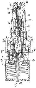
[020] The dosing device has an attachment sleeve in the form of a collet 1,
which
can be screwed on to a container neck of the medium reservoir. The attachment
sleeve 1 carries a pump casing 2, 3, 4, which is assembled from two components
2 and 3 held in stationary manner relative to the attachment sleeve 1 and
there-
fore the medium reservoir, and a pump component 4 mounted in linearly movable
manner relative to the stationary components 2, 3. Pump component 4 forms an
applicator of the dosing device and which in the embodiment shown is in the
form
of a nasal applicator.
[021] Into the medium reservoir projects a rising tube 19, which is inserted
in a
not shown inlet channel of component 2. In the embodiment shown the inlet chan-
nel is hollow cylindrical. Rising tube 19 is also cylindrical. Component 2
consti-
tutes a support component. Support component 2 has an upwardly open, cup-like
CA 02641096 2008-07-31
6
receptacle, into which is pressed the stationary pump component 3 and which in
this way is rigidly connected to the support component 2. The stationary pump
component 3 and movable pump component 4 define a pumping chamber 10,
which extends into a top region of the pump component 4 and there issues into
a
dosing opening 12 which is open to the environment. In the embodiment shown
the dosing opening 12 is in the form of a spray nozzle.
[022] Pump component 4 has a multipart construction, in that it is assembled
from
an outer, hood-like applicator casing 4' and a piston component 5, 6. Between
the
applicator casing 4' and the piston component 5, 6 is provided an outlet valve
11,
which is held in a limited linearly movable displaceable manner coaxially to a
pumping axis P of the dosing device in the applicator casing and the piston
com-
ponent 5, 6. Outlet valve 11 is held in its closed position in fig. 1 by a
spring ar-
rangement 16 in the form of a helical compression spring. With its sleeve-like
guide wall, piston component 5, 6 surrounds the outlet valve 11 in sealing
manner
towards pumping chamber 10. A not shown, hood-like cover is also placed on
applicator casing 4'. To the applicator casing 4' is also externally connected
a not
shown finger support, which according to fig. 1 is locked on to the applicator
cas-
ing 4'. Piston component 5, 6 has a dosing piston 6 oriented coaxially to
pumping
axis P and which is substantially cylindrical. Dosing piston 6 widens
downwards
to a sealing lip 7, which forms an inlet valve in the manner of a slide valve.
The
circumferential sealing lip 7 cooperates during its function as a slide valve
with a
dosing channel 8, which is provided coaxially to pumping axis P in pump compo-
nent 3. Dosing channel 8 defines a dosing path for the sealing lip 7. At the
outlet
side the dosing channel 8 passes into pumping chamber 10. On the inlet side to
dosing channel 8 is connected an inlet area 9, which has a widened free cross-
section compared with dosing channel 8. In the case of a corresponding longitu-
dinal displacement the slide valve opens at the transition of sealing lip 7
from dos-
ing channel 8 to inlet area 9, because the widened cross-section of inlet area
9 is
such that liquid can flow past the sealing lip 7 on the outside into dosing
channel 8
and therefore into pumping chamber 10. Further details will be given of the de-
sign of inlet area 9 hereinafter.
CA 02641096 2008-07-31
7
[023] The dosing devices according to figs. 1 and 2 are substantially
identical to
one another, but differ in the construction of inlet area 9, 9a respectively
and to
this extent differing embodiments will be described hereinafter. It is common
to
both embodiments that the inlet area 9, 9a has three longitudinal grooves 20
(fig.
3) or 21 (fig. 4), which are made in an annular wall of inlet area 9, 9a. In
the em-
bodiment according to figs. 1 and 2 the longitudinal grooves 21 are relatively
nar-
row. in the embodiment according to figs. 2 and 3 they are correspondingly
wider.
The longitudinal grooves are distributed in uniformly spaced manner over the
cir-
cumference of the otherwise cylindrical inlet area 9, 9a and extend parallel
to
pumping axis P. At its wall portions located between the longitudinal grooves
20,
21, the diameter of inlet area 9, 9a preferably corresponds at least
substantially to
the diameter of dosing 8, 8a.
[024] On its front side facing the medium reservoir, to inlet area 9, 9a is
con-
nected a diaphragm B, whose passage cross-section is smaller than the passage
cross-section of dosing channel 8 and inlet area 9. However, the passage cross-
section of diaphragm B is larger than the free channel cross-section of rising
tube
19, which is connected to the diaphragm B on the side thereof facing the
medium
reservoir. Diaphragm B additionally serves as an insertion stop for the rising
tube
19.
[025] In the embodiment of fig. 1 the inlet area is shaped integrally in the
pump
component 3. However, diaphragm B is integrally shaped on to support compo-
nent 2, as can be gathered from fig. 1. For this purpose support component 2
forms coaxially to pumping axis P a dome-like bulge, which is frictionally
inserted,
particularly pressed into a corresponding sleeve-like receptacle of pump compo-
nent 3 and on its front side facing inlet area 9 terminates with the
integrally
shaped diaphragm B, which is oriented radially to pumping axis P. Thus, by
means of a stepped annular shoulder, inlet area 9 of pump component 3 passes
into the sleeve-like, cylindrical receptacle into which is pressed said
support com-
ponent with its corresponding, cylindrically designed bulge. Longitudinal
grooves
21 are closed at the end towards dosing channel 8, but are open towards its
fac-
ing front end.
CA 02641096 2008-07-31
8
[026] In the embodiment according to figs. 2 and 3 the inlet area 9a,
including the
diaphragm B, is an integral part of support component 2a. For this purpose the
support component 2a is provided with an upwardly projecting, rim-like
extension
into which is integrated inlet area 9a. Diaphragm B is shaped integrally below
inlet area 9a. Support component 2a is inserted, coaxially to pumping axis P,
with
a rim-like extension into a corresponding cylindrical receptacle of pump compo-
nent 2a and is tightly and frictionally connected to pump component 3a. The
wide
longitudinal grooves 20 of inlet area 9a are also frontally closed towards
dosing
channel 8a. They are also closed through the construction of diaphragm B to-
wards the opposite front end thereof.
[027] With both embodiments according to figs. 1 and 2 and 2/3, the facing cir-
cumferential surfaces of the pump component 3, 3a and support component 2, 2a
are provided with circumferential profilings 18 in the vicinity of their
mutually
engaging wall surfaces in the telescoped state. The profilings 18 are such
that
gas-permeable flow guide paths are obtained in the form of capillary tubes be-
tween a lower front edge of the outer circumferential surface of pump
component
3a and an upper front edge of said circumferential surface. Thus, a liquid-
tight
connection between the components is created in the vicinity of profilings 18.
However, simultaneously a gas exchange, particularly an air exchange is made
possible between the medium reservoir and environment through the at least one
capillary tube formed between components 2a/3a or 2/3 respectively.
[028] Ambient air access to the medium reservoir is made possible by means of
a
passage provided in support component 2a and in which is inserted a filter com-
ponent 17 serving as a filter unit. Both embodiments according to figs. 1 and
2 are
identical with respect to the design of the outlet valve 11 and outlet area of
appli-
cator casing 4', so that the following statements made relative to figs. 5 and
6 ap-
ply to both embodiments.
[029] As is apparent from figs. 5 and 6, on its front side facing dosing
opening 12
outlet valve 11 is provided with a cylindrical extension oriented coaxially to
pump-
ing axis P and forming a sealing stem 13. Following inwards on to the inwardly
conically widened dosing opening 12, an outlet area of applicator casing 4' is
pro-
CA 02641096 2008-07-31
9
vided with a corresponding cylindrical valve seat 24. Sealing stem 13 and
valve
seat 24 form both an axial and a radial sealing seat in the closed state of
outlet
valve 11 according to fig. 5. Around the sealing stem 13 is provided a
cylindrical
ring-like labyrinth rim 15 which, like the sealing stem 13, is shaped
integrally on to
outlet valve 11. Labyrinth rim 15 also protects the sealing stem 13 against
dam-
age. The annular labyrinth rim 15 has the same cross-section all-round. The
cross-section is substantially rectangular, as is apparent from fig. 5. The
labyrinth
rim 15 has a reduced height compared with that of sealing stem 13. Between
labyrinth rim 15 and sealing stem 13 there is an annular clearance, whose
width in
the embodiment shown roughly corresponds to the width of labyrinth rim 15 and
has a rectangular, internal cross-section.
[030] In a not shown embodiment the labyrinth rim is at least precisely as
high as
the sealing stem, which brings about a particularly good protection against
dam-
age for said stem.
[031] Valve seat 24 is provided in a sleeve-like annular extension of the
applicator
casing 4', which is coaxial to pumping axis P, projects inwards and serves as
a
shell portion. The annular extension projecting into the interior of
applicator cas-
ing 4' is provided on its axially inner front side with a centring cone 20,
which de-
fines a wall surface conically tapering towards dosing opening 12. In the
conically
tapering wall surface are integrated several longitudinal grooves 23
distributed
over the circumference of the annular extension of applicator casing 4' and
which
continue into the valve seat 24 in axially parallel manner to pumping axis P
and as
is apparent from fig. 6. Thus, sealing stem 13 forms only an axial sealing
seat
with valve seat 24, because the flow path to dosing opening 12 is already
freed
when the sealing stem 13 has moved slightly axially away from the
corresponding
front face of valve seat 24. The liquid to be discharged can then be
transported
through the longitudinal grooves 23 upwards past the circumferential surface
of
sealing stem 13 to dosing opening 12 without the sealing stem 13 having to com-
pletely leave its radial guidance within the valve seat 24. As a function of
the
pressure buildup and maximum lift mobility of outlet valve 11, the latter can
also
be moved out of valve seat 24 to such an extent that the liquid can flow over
the
CA 02641096 2008-07-31
conical faces of centring cone 22 to dosing opening 12, without having to flow
ex-
clusively through longitudinal grooves 23.
[032] Around the annular extension comprising valve seat 24 is provided in the
interior of applicator casing 4' an annulus 14 into which is introduced the
labyrinth
rim 15. The inner contour of annulus 14 has wall surfaces running parallel to
the
wall surfaces of labyrinth rim 15, as is apparent from the cross-section of
fig. 5.
Fig. 5 also shows that in the closed state of outlet valve 11, the wall
surfaces of
annulus 14 are so spaced with respect to the adjacent wall surfaces of
labyrinth
rim 15 that there is a clearance up to sealing stem 13. The clearance serving
as a
fluid guide path is already provided between the bottom circumferential
surfaces
of outlet valve 11 from the inner wall of applicator casing 4' with roughly
the same
thickness as in the upper labyrinth or outlet area of annulus 14 of applicator
cas-
ing 4. On opening outlet valve 11 the liquid flow between annulus 14 and laby-
rinth rim 15 and the radially inwardly following annular extension is
deflected in
labyrinth-like manner before it reaches centring cone 22 and consequently
longi-
tudinal grooves 23. This makes it possible to obtain a particularly precise
and ad-
vantageous dosing or spray characteristic.
[033] The dosing device of fig. 7 has a manually actuatable pumping means,
which is functionally identical to the pumping means of the previously
described
embodiments according to figs. 1 and 2. Functionally identical components
carry
the same reference numerals, but a letter b is added. To avoid unnecessary
repe-
tition, for the description of the functionally identical components given the
same
reference numerals, reference is made to the description of the preceding em-
bodiments.
[034] The essential difference of the dosing device according to fig. 7 is
that the
applicator casing is constructed in such a way that the outlet valve 11 b and
dosing
or discharge opening 12b are oriented at right angles to the pumping axis P.
Thus, the pumping chamber 10b is also provided with flow guide paths deflected
at right angles. On the inside of labyrinth rim 1 5b facing the valve seat of
the ap-
plicator casing, which surrounds in annular manner sealing stem 13b, is
provided
a flat, spherical annular groove PG, which further improves the flow
characteristic
CA 02641096 2008-07-31
11
in the vicinity of the labyrinth rim and consequently a further improved
spraying
action.
[035] It is an important idea of the inventive solution, as described relative
to the
embodiments of figs. 1 to 7, that in the vicinity of the inlet valve of
pumping cham-
ber 10, namely in the vicinity of slide valve 6, 7 and/or in the vicinity of
outlet valve
11, namely in the outlet area directly upstream of the dosing opening 12,
there are
annular walls in each case provided with flow profilings in order in this way
to be
able to positively influence the inflow/outflow characteristic of the liquid
into or out
of the pumping chamber.