Note: Descriptions are shown in the official language in which they were submitted.
CA 02641229 2015-05-19
SYSTEMS AND METHODS FOR REMOTE UNMANNED
RAMAN SPECTROSCOPY
[0001]
FIELD OF THE INVENTION
[0002] The present invention is related to Raman spectroscopy, and more
particularly to
systems and methods for integrating Raman spectroscopy functionality with an
unmanned ground vehicle, such as a robot.
BACKGROUND OF THE INVENTION
[0003] The danger of exposure to chemical or biological agents can be severe.
Whether a
result of unintended release, by way of, e.g., an accident, or intentional
delivery, it is
desirable to quickly and accurately identify (1) the type of agent that has
been released
and (2) the precise area of contamination. Early and accurate detection of
such dangerous
substances can be a significant factor in reducing potential casualties and
limiting further
spreading of the agent, e.g., by wind, human and animal contact, etc.
[0004] In recent years, there has been an increased interest in developing and
deploying
nuclear, biological, and chemical (NBC) sensor technologies to quickly
identify unknown
substances, contaminants, and agents, even at very low concentrations. Prior
technologies designed to measure surface-deposited chemical contamination used
vehicles and associated test equipment that retrieved a physical sample of the
contaminant and then used an extremely cumbersome and time-consuming process
based
on a mechanical sampling wheel system to test for chemical agents.
[0005] In view of the complexity of such approaches, newer, simpler
technologies were
desired. One emerging technology in response to this desire is referred to,
generally, as
"standoff surface detection," and refers to a category of technologies that
permit detection
of a substance without actually having to physically come in contact with the
substance.
The goal of these detection systems is to provide the capability to detect,
identify, locate,
quantify, warn, and report chemical and biological threats and thereby give
military
forces or civilian personnel sufficient early warning to avoid (further)
contamination.
CA 02641229 2015-05-19
[0006] One of the technologies that enables standoff surface detection is
Raman
spectrometry. Raman spectrometry is a technique used to characterize materials
and
thereafter to identify such materials. Typically, a laser transmitter serves
as a spectrally
narrow light source with high irradiance. The laser illuminates a known or an
unknown
substance, such as chemical compounds, biological agents, among others. A
portion of
the incident light is Raman scattered by the substance. This light is
scattered in all spatial
directions as well as shifted spectrally into several discrete wavelengths.
These
wavelength shifts correspond to unique vibrational energies associated with
the molecular
bonds in the substance.
[0007] In conventional Raman spectroscopy systems, the Raman scattered light
is
collected by a telescope and is coupled into a dispersive optical system. The
telescope
focuses the collected light onto, e.g., an optical fiber bundle. At the
opposite end of the
fiber bundle, individual fibers are oriented linearly to form an entrance slit
for a grating-
based spectrograph. An electro-optical detector array records the optical
spectrum of the
Raman scattered light. This spectrum serves as a "fingerprint" for the known
or unknown
substance. An analysis computer either stores the "fingerprint" along with
information
identifying the known substance, or more often, employs pattern-matching
algorithms to
identify the unknown substance from a spectral library of previously analyzed
and
"fingerprinted" substances.
[0008] Laboratory-based Raman spectrometry systems have been known for many
years.
Recently, portable Raman systems have become possible as a result of
components that
have decreased in size. A description of one such portable system can be found
in U.S.
Patent 6,608,677. A backpack implemented man-portable Raman sensor has also
recently been fielded by ITT (Wilmington, DE). Aspects of that system are
described in
U.S. Patent No. 7,796,251, entitled Method, Apparatus and System for Rapid and
Sensitive Standoff Detection of Surface Contaminants, and filed March 20,
2007. Truck
mounted Raman sensors have also been fielded to date. Reference may also be
made to
U.S. Patent 6,788,407 for still further discussion of Raman spectrometry.
2
CA 02641229 2015-05-19
[0009] Notwithstanding these known systems, there remains a need to provide
different
forms of Raman sensors to meet the needs of both civilian and military
personnel
responsible for identifying and ultimately handling dangerous substances and
items.
SUMMARY OF THE INVENTION
[0010] The present invention provides a unique implementation of a Raman
spectroscopy
sensor in which components of the system are mounted on, or, more preferably,
closely
integrated with, an unmanned ground vehicle (UGV) or robot that operates
autonomously
or that is controlled by a remote user. With this type of configuration, users
of the Raman
sensor can avoid having to be in the vicinity of dangerous substances or
items. More
particularly, with embodiments in accordance with the present invention,
personnel are
provided the capability to perform remote yet sensitive site exploitation
including
inspection of buildings, equipment, vehicles, aircraft, and other manmade or
natural
surfaces for the presence of unknown substances or items including, but not
limited to,
explosive material (e.g., TNT and RDX), homemade explosives and their
precursors, and
chemicals including chemical warfare agents (CWAs), and toxic industrial
chemicals
(TICs). One significant advantage of embodiments of the present invention is
the ability
to search for and detect improvised explosive devices (IEDs) without having to
place
people in the same location in which explosives might be hidden.
[0011] Other advantages of embodiments of the present invention include the
fact that
the technology (1) is non-contact (i.e., it is a standoff system), (2) allows
mapping of the
surface contamination, and (3) provides quick response (typically only seconds
to
perform detection).
[0012] In an embodiment, the present invention provides a UGV that includes a
robot
arm that may be steerable on its own or by way of steering the UGV itself The
UGV is
preferably remotely controlled through a radio frequency (RF) link. The robot
arm
preferably includes a camera, and images from the camera are preferably
streamed (over
the RF link) back to a control station from which an operator can control the
UGV. In
3
CA 02641229 2008-10-17
=
this way, the operator can appropriately steer the UGV and point the camera
towards
targets of interest.
[0013] In addition to the foregoing, the UGV preferably also includes
components of a
Raman sensor. Specifically, along with the camera on the robot arm, there is
preferably
mounted a laser and associated telescope. As mentioned, in Raman spectroscopy
the
laser irradiates a desired location and the telescope gathers Raman scattered
spectra.
These spectra, in accordance with the present invention, are passed through an
umbilical
that includes, e.g., a bundle of optical fibers, to a sensor that is on board
the UGV. The
sensor may include a spectograph, a data acquisition and control module, a
power
conditioning module and an RF module that may be the same as an RF module that
controls the UGV, or a separate RF module that is dedicated to controlling and
communicating with the Raman sensor components.
[0014] A base station is preferably also provided for a remote operator to
monitor and
control the Raman sensor aspects of the UGV. In this regard, the base station
preferably
includes a data processing and analysis module and a display, such as a touch-
screen
display to facilitate operation of the system. The base station may be
integrated with the
control station of the UGV or may be separate. Indeed, it is contemplated that
the
operator of the UGV may not be the same operator of the Raman sensor. In this
regard,
the two separate operators need not even be in the same location.
[0015] In a preferred embodiment, an automatic telescope focusing mechanism is
implemented that operates effectively even within constraints set by the
limited space and
weight allowance on the robot arm.
[0016] In still another possible embodiment, the Raman sensor components of
the UGV
are configured to be compatible with a man-portable/backpack version of a
Raman sensor
such that depending on the circumstances, e.g., nature of terrain or
environment,
perceived threat, etc., personnel may have the option of using a UGV or having
personnel
directly approach a target of interest.
[0017] The following is a list of the some preferred features of an embodiment
of the
present invention:
4
CA 02641229 2008-10-17
[0018] A compact remote sensor;
[0019] Warm up of less than 20 minutes;
[0020] Remotely adjustable standoff range (0.5 to 10 meters);
[0021] High flexibility in line-of-sight pointing direction using manual
aiming or through
the use of the UGV's remotely controlled arm;
[0022] Contamination mapping;
[0023] Radio Frequency (RF) link to a remoted (outside the area being
surveyed) base
station;
[0024] Rapid (<30 seconds) detection and identification of surface
contaminants;
[0025] Simple, low-maintenance operation;
[0026] High selectivity/probability of detection with low false alarm rates;
[0027] Ruggedized for the operational environment; and
[0028] Capable of detecting and handling unknown substances.
[0029] These and other features of embodiments of the present invention and
their
attendant advantages will be more fully appreciated upon a reading for the
following
detailed description in conjunction with the associated drawings.
BRIEF DESCRIPTION OF THE DRAWINGS
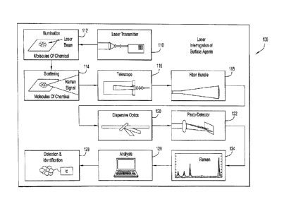
[0030] Figure 1 is a schematic functional diagram of a Raman spectrometry
system that
may be employed with embodiments of the present invention.
[0031] Figures 2 and 3 are graphs of Raman spectra for the explosive TNT.
[0032] Figure 4 shows, in block diagram form, an embodiment of the present
invention.
[0033] Figure 5 depicts an unmanned ground vehicle with which the present
invention
may be integrated.
[0034] Figure 6 depicts an autofocus system in accordance with the present
invention.
CA 02641229 2008-10-17
DETAILED DESCRIPTION
[0035] Figure 1 is a schematic functional diagram of a Raman spectrometry
system 100
that may be employed with embodiments of the present invention. As shown, a
laser
transmitter 110 serves as a spectrally narrow light source with high
irradiance. It
illuminates a chemical agent deposited on a surface as indicted by functional
block 112.
A portion of the incident light is Raman scattered by the chemical compound,
as
indicated by functional block 114. This light is scattered in all spatial
directions as well
as shifted spectrally into several discrete wavelengths. These wavelength
shifts
correspond to the unique vibrational energies associated with the molecular
bonds in the
given chemical.
[0036] The Raman scattered light is collected by a telescope, block 116, and
is coupled
into a dispersive optical system. More specifically, a telescope focuses the
collected light
onto an optical fiber bundle 118. At the opposite end of the fiber bundle,
individual
fibers are oriented linearly to form an entrance slit for a grating-based
spectrograph 120.
An electro-optical detector array 122 (including, for example, an intensified
charge
coupled device (ICCD)) records the optical spectrum of the Raman scattered
light 124.
This spectrum serves as a "fingerprint" for the chemical compound. An analysis
computer 126 employs pattern-matching algorithms to identify the chemical from
a
spectral library of known compounds, and ultimately identifies a specific
compound 128.
[0037] Detection of explosive materials, in particular, has become
increasingly important
in recent years. Both civilian and military authorities have a great need to
quickly
identify explosive devices so that appropriate alerts, evacuations, defusing
or eradicating
efforts can get under way.
[0038] In this regard, it has recently been determined that the use of UV
laser excitation
maximizes the efficiency of Raman scattering from explosive chemicals.
Techniques
such as Laser Induced Breakdown Spectroscopy (LIBS) are not as selective or as
mature
a technology as Raman spectroscopy, while others like Laser Induced
Fluorescence (LIF)
are not as specific, and even limited, in that some explosive materials are
non-
fluorescing. The principal advantage of UV Raman spectroscopy over
conventional
visible-excitation Raman spectroscopy is sensitivity. UV excitation
wavelengths
6
CA 02641229 2008-10-17
intrinsically scatter more strongly than visible wavelengths. Moreover, many
explosive
chemicals strongly absorb UV radiation, and this increases the Raman
scattering
efficiency by many orders of magnitude through an effect called resonance
enhancement.
Resonance enhancement is particularly strong for chemical functionalities such
as
aromatic rings and nitro groups, both of which are common features of
explosive
compounds. Ultimately, the strength of the collected UV-Raman signal depends
on
several factors, including target concentration, wavelength-dependent
absorption, and
scattering properties of the target. The relationship between these parameters
is discussed
in more detail below using the explosive material TNT as an example.
[00391 A detailed analysis of the UV-Raman spectra for several samples of TNT
indicate
that the Raman scattering efficiency for 262-nm (UV) laser excitation is ¨105
times
greater than found for conventional 532-nm (Green) excitation, which is
indicative of
strong resonance enhancement. Shown in Figure 2 is the 262-nm Raman spectrum
for an
11 mM solution of military-grade TNT in acetonitrile. At this concentration,
the
acetonitrile molecules outnumber the TNT molecules ¨1800:1, yet the Raman
bands of
TNT (solid trace) carry intensities that are comparable to those belonging to
acetonitrile
(dotted trace). Clearly, scattering from TNT is strongly enhanced with 262-nm
excitation. By comparison to the known 262-nm scattering cross section for
acetonitrile,
it has been has determined that the 262-nm scattering cross section for TNT is
3x10-25
cm2/molecule. In contrast, the 532-nm Raman spectrum of the same sample yields
no
detectable TNT Raman bands, which is consistent with the much weaker
scattering
expected at this wavelength (-1x10⁻³ cm2/molecule or 300,000 times weaker).
Notably,
the 11-mM concentration and 1 mm path length used for this sample is
equivalent to a
TNT film 1.5 um thick, suggesting that thin films of explosive materials are
best
measured with UV Raman.
100401 The strongly enhanced Raman signals provided by 262-nm laser excitation
provides the sensitivity needed to detect and identify TNT at trace
contamination levels.
Strong absorption at 262 nm limits the number of molecules that contribute to
the
measured Raman signal to those found in the first 90-nm layer of TNT,
regardless of
sample thickness. The fact that the 11-mM solution described above and a bulk
solid
7
CA 02641229 2008-10-17
sample of TNT yield comparable signal levels validates the claim that
absorption limits
the 'interaction depth', which is defined herein as the sample thickness that
yields 90% of
the collected return signal expected from an infinitely thick sample. The key
point is that
the majority of the collected signal, like that shown in Figure 2, is
obtainable from an
extremely thin film of TNT (< 100 nm).
[0041] Recently, Lincoln Laboratory reported that explosive chemicals can be
found at
concentrations exceeding 20 ug/cm2 on the exterior surfaces of vehicles that
come into
contact with the hands and feet of individuals who are involved with
explosives, e.g.,
IEDs. Based on these findings, Lincoln Laboratory concluded that a UV Raman
spectrometer equipped with a 1-W laser operating at 266-nm and a 30-cm
collection
aperture would be incapable of collecting Raman photons at detectable levels,
even at
standoff distances below 10 m. However, since UV-Raman scattering cross
sections for
TNT were not available at the time of publishing, the authors used a value of
lx10-3
cm2/molecule. Importantly, the authors recognized that strong resonance
enhancement
may in fact overcome the poor performance predicted by their model. The data
in Figure
2 indicate that the scattering cross section at 266 nm is indeed several
orders of
magnitude greater (-1x10-25 cm2/molecule), which confirms their hypothesis
regarding
the impact of strong resonance enhancement on performance: the Raman
spectrometer
described by Lincoln Laboratory would in fact collect ¨105 Raman
photons/second at a
standoff distance of 5 m, which is significantly more than originally
predicted. Notably,
a 4 cm2 print with an evenly distributed TNT mass loading of 20 ug/cm2 is ¨30
nm thick,
which is comparable in magnitude to the interaction depth for TNT at 262 nm.
This
suggests that the UV-Raman technology employed in the instant invention is
well suited
for detecting TNT at the contamination levels found on vehicle exteriors as
reported by
Lincoln Laboratory. In fact, TNT detection capabilities with UV-Raman
spectroscopy
have already been confirmed. Figure 3 shows the 262-nm Raman spectrum of TNT
recorded with a Raman spectrometer employed by embodiments of the present
invention.
The data in Figure 3 were collected in one second at a standoff distance of
one meter.
[0042] While TNT and other explosive materials detection using Raman
spectroscopy is
increasingly accurate, as described above, there remains a problem that
personnel should
8
CA 02641229 2008-10-17
. .
preferably avoid being in the vicinity of explosives in the first place. Prior
art stand off
detection systems, including Raman sensors, require that personnel at least
approach
mysterious devices or surfaces that are to be analyzed. The present invention
overcomes
this potentially dangerous scenario by spatially separating the sensor from
the operator.
100431 Figure 4 shows, in block diagram form, an embodiment of the present
invention.
As shown, the system comprises an underlying unmanned ground vehicle (UGV) 410
including a UGV camera 420 mounted on an arm 425 extending from a body of the
UGV
410 and a remote UGV/Camera Arm Control Station 430. UGV/Camera Arm Control
Station 430 is preferably in communication with UGV 410 via a radio frequency
(RF)
link 435 and is operable to command UGV 410 and arm 425 to move in a selected
direction, turn, stop, etc., all from a remote location. While such an RF link
435 provides
the greatest degree of freedom for UGV 410 and an operator, it may be
preferable under
certain circumstances to have a wired connection between UGV 410 and
UGV/Camera
Arm Control Station 430. For example, a fiber optic wire may be used to
remotely
control UGV 410, arm 425 and camera 420, among other elements on UGV 410. One
possible UGV that may be used in connection with the instant invention is the
MATILDA II robotic platform shown in Figure 5 and available from Mesa
Robotics, Inc.
(Madison, AL). Although not shown in Figure 5, the MATILDA II robot also
includes a
remotely operated UGV/Camera Arm Control Station 430, which may be operated by
an
operator of the UGV.
[0044] Referring again to Figure 4, integrated with UGV 410 in accordance with
an
embodiment of the present invention are components associated with a Raman
spectrometer or sensor. These components include a Laser/Telescope module 450
that is
mounted on the UGV itself, or more preferably, on the robot's arm 425 as
shown. An
umbilical (e.g., cable or collection of cables) 455 that comprises, for
example, the fiber
bundle described above, connects the Laser/Telescope module 450 to a Sensor
module
460. Sensor module 460 comprises several components including a Spectograph
462 for
receiving optical Raman spectra from the telescope of the Laser/Telescope
module 450, a
Data Acquisition & Control unit 464 that captures the spectral data using,
e.g., an
intensified charge coupled device (ICCD) camera, a power conditioning unit 466
for
9
CA 02641229 2008-10-17
providing appropriate electrical power to the several components and modules
associated
with the Raman spectrometer and related equipment, and an RF unit 468 that is
configured to wirelessly exchange communications with a base station 480.
[0045] Base station 480, itself, comprises an RF unit 482 that maintains
wireless
communications 471 with RF unit 468, a Data Processing & Analysis module 484
and a
display 486. While Data Processing & Analysis module 484 is shown as being
part of
base station 480, the functionality of this module may likewise be located on
UGV 410.
The primary purpose of Data Processing & Analysis module 484 is to perform
spectral
pattern matching against a library of known Raman spectra, and attempt to
identify a
substance then being irradiated or that has been irradiated by the laser on
the UGV 410.
Display 486 may then alert an operator of the possible substance
identification, and
provide further information such as steps to take in light of the type of
substance
identified, or information about whom to contact to initiate remediation.
[0046] In accordance with one possible implementation, if a received spectral
signal is a
"persistent unknown" (e.g., it is not a member of the current library), the
system provides
the operator the options of: (1) adding the signature to the library as an
important
unknown, (2) ignoring the detected signature, or (3) postponing any decision
until the
next occurrence of the unknown. Information regarding received spectral
information
may be presented to an operator via display 486, and the operator may be
requested to
provide input to the system, via, e.g., a touch screen capabilities of display
486.
[0047] It is noted that Figure 4 depicts UGV/Camera Arm Control Station 430
and base
station 480 as separate components. However, it may be preferable that a
single
integrated control mechanism be implemented for the system to facilitate
control thereof,
e.g., using one set of controls, one display, etc. Such integrated control is
designated by
reference numeral 490. With one display, for example, an operator may be able
to view
precisely what the laser is interrogating. More specifically, images from UGV
camera
420 may be streamed back to a display, which display is also operable to
depict what the
laser of Laser/Telescope module 450 is irradiating. Consequently, if, e.g., an
explosive
substance is identified, the operator can more easily identify the object on
which the
explosive material traces have been found, and thereby communicate that
information to
CA 02641229 2008-10-17
an explosives demolition expert. Such images may further be stored for later
use, e.g.,
for training. Moreover, the display may show a real time video of where the
robot is
looking and include overlay or tiled views on the display showing the results
of the
Raman interrogation.
[0048] In an alternative embodiment, the UGV/Camera Arm Control Station 430
and the
base station 480 are purposefully maintained as distinct functional units
thereby allowing
the possibility for different operators to operate respective components of
the system,
even when those operators are not in the same location.
[0049] The distance or range at which the Raman spectroscopy system on the UGV
can
practically detect substances is a factor in the configuration of the remote
unmanned
Raman spectroscopy system of the present invention. While a 20 mW laser is
effective at
3 meters (with 1 second dwelling on a target) for detecting surface
contaminants, it is
preferable that the range of the system be more on the order of ten meters.
Consequently,
a more powerful laser is preferably used in order to ensure that sufficient
laser power can
be delivered to a selected target. In one possible implementation, a 500 mW
263 nm
laser available from, e.g., Photonics Industries (Bohemia, NY) may be employed
to
obtain the necessary power for increased range. Of course, other lasers and
powers
sufficient to deliver appropriate power to a target contaminant may also be
used.
[0050] Additionally, for ranging of this magnitude (ten meters), the telescope
component
of the Laser/Telescope module 450 is preferably able to focus over a range of
0.5 to 10
meters. In one possible implementation, an electrically activated focusing
mechanism
can be used in conjunction with internal pointing diodes and the UGNPs camera
420 to
adjust focus remotely. That is, by monitoring a field of view of the UGV's
camera 420,
an operator can remotely focus the optical components of the Laser/Telescope
module
450. Alternatively, an automatic focus (autofocus) system may be implemented
to
thereby relieve the operator of having to manually control telescope focus.
This can save
time, and increase accuracy of detection. A detailed discussion of an
autofocus system
that may be employed in connection with the instant invention is provided
later herein.
[0051] In one possible implementation, the Raman spectroscopy components of
the
system may be modular components that can be shared with a man-portable
version
11
CA 02641229 2015-05-19
Raman sensor. A description of such a man-portable Raman detection system can
be
found in U.S. Patent No. 7,796,251, as mentioned previously. The man-portable
detection system described therein includes a hand-held unit, a processing
unit and an
umbilical cable that connects the hand-held unit with the processing unit. In
an
embodiment described therein, at least portions of the processing unit are
contained in a
wearable backpack.
[0052] In accordance with embodiments of the instant invention, selected
components of
Raman spectroscopy system mounted or integrated with UGV 410 are modularized
such
that they can also be used with a man-portable Raman detection system. More
specifically, the hand-held unit described in U.S. Patent No. 7,796,251 may be
configured
such that it has similar functionality to the Laser/Telescope module 450 shown
in Figure
4. Likewise, umbilical 455 of the present invention may be configured
similarly to the
umbilical cable described in U.S. Patent No. 7,796,251. Finally, sensor module
460 may
be configured to have similar functionality to the processing unit described
in U.S. Patent
No. 7,796,251. Similar respective enclosures may also be provided for the
several
possibly modular components identified above. With such modularity, an overall
system
for detecting unknown substances might include a combination system that
comprises
both a UGV sensor and a man-portable sensor, wherein personnel in the field
can easily
select and enable either type of system (UGV or man-portable) depending on the
perceived threat, or any other consideration.
[0053] In a preferred embodiment, components such as the Laser/Telescope
module 450,
umbilical 425 and Sensor module 460 are available to personnel as Line
Replaceable
Units (LRUs), thereby making field repairs relatively simple. Because
components such
as the Laser/Telescope module 450 and Sensor module 460 are likely to be
exposed to the
elements for significant amounts of time, enclosures for these components
preferably
have appropriate environmental seals (to guard against rain, decontamination
spray
booths, etc.), are EMI/EMC hardened (particularly for military applications),
and have
appropriate shock/vibration isolation.
12
CA 02641229 2015-05-19
[0054] Wireless link 471 may be a high bandwidth, spread spectrum RF data
link.
Wireless link 435 may also be integrated with wireless link 471, or may be a
separately
operated link (e.g., different frequency, different modulation technique,
etc.).
[0055] Base station 480 may be a centralized device, and have the capability
to monitor
not just one UGV, but possibly multiple UGVs. When multiple UGVs are being
used
simultaneously and only one operator is available, then autonomous operation
of the
UGV may be preferable. In any event, an output of the base station 480 may
also be
connected via an electronic network, e.g., Ethernet (wired or RF), to a scene
commander's workstation that integrates the activities of all fielded UGVs or
man-
portable devices.
[0056] Regarding UGV 410, it is preferable to employ a robot that is small
enough to use
inside buildings and tunnels while maximizing its payload. The MATILDA II
robot
identified above has a payload capacity on the order of 125 pounds and can
operate for
six hours on its batteries. The man-portable backpack and wand described in
U.S. Patent
No. 7,796,251 weigh about 46 pounds including a 1-hour battery. The robotic
arm 425 of
the MATILDA robot weighs about 45 pounds and has a payload capacity of about
35
pounds. The weight of Laser/Telescope module 450 is on the order of 5 to 20
pounds.
Thus the robotic arm 425, Laser/Telescope module 450, and Sensor module 460
weigh
less than 105 pounds, leaving 20 pounds for additional batteries.
[0057] The batteries may be standard military battery packs (e.g. 5590, 2590),
or may be
more advanced batteries with higher energy densities. Battery selection
impacts the
length of time the UGV 410 may be able to operate, but is otherwise not
critical to the
instant invention.
[0058] From the foregoing, those skilled in the art will appreciate that
components of a
Raman spectrometer mounted on or integrated with a UGV in accordance with the
present invention yields a compact remote sensor with remotely adjustable
standoff range
of 0.5 to 10 meters, thus enabling operators to analyze a host surfaces in the
vicinity of
the UGV 410. In one implementation, the UGV arm 425 is used to aim the
Laser/Telescope module 450. By capturing location data of the UGV and position
data of
the arm 425, such as by use of GPS and well-known position encoders, it is
also possible
13
CA 02641229 2008-10-17
to generate coordinates of individual suspect locations and devices, as well
as to help
generate a map of the extent of surface contamination or locations of
potential explosive
devices. Such maps or mapping data can be integrated with other geographical
information systems that may further assist personnel in tracking and removing
undesirable agents and devices.
[0059] In a preferred embodiment, and as mentioned, the UGV and Raman sensor
are
controlled remotely through an RF link to a remote site, thereby ensuring that
personnel
are not put in unnecessary danger. The operator may be at a nearby location,
or may be
located at a significantly distant location.
100601 Also, because spectral pattern matching can be performed within
seconds, it is
possible to identify unknown agents within, typically, less than 30 seconds.
This allows
the UGV to make many hundred or even thousands of interrogations during the
lifetime
of a single set of batteries. The spectral data collected is also normally
very unique, and
thus the system as a whole may provide high selectivity/probability of
detection with low
false alarm rates.
[0061] As mentioned previously, it may be desirable to implement an autofocus
system
with the telescope optics to enable a standoff range of 0.5 m to 10 m for the
Raman
detection system of the present invention. However, because of the limited
space on the
robotic arm, the limited amount of weight that can be added to the robot arm
425, and the
overall UGV in general, it is desirable to have a compact yet capable focusing
apparatus
with sufficient fidelity to provide a range of operation over the entire 0.5
to 10 m.
[0062] More specifically, depth of focus of an optical system is proportional
to the square
of the of the collection optics F/#. When target distance varies ¨ due to
operator motion
or target height variations ¨ to maintain good focus over the full range of
target distances,
F/# has to be large. However, collected light is inversely proportional to the
square of the
F/4. Thus, there is a fundamental incompatibility between the need for large
F/4 to
provide large depth of focus and the need for small F/4 to allow collection of
more
Raman scattered light.
[0063] However, implementing an autofocus system capable of maintaining
precise focus
as target distance varies, the need for large depth of focus ¨ and hence large
F/# ¨ goes
14
CA 02641229 2008-10-17
away. Small F/# collection optics can now be used that collect more Raman
scatter,
giving a corresponding increase in overall Raman sensor system SN ratio.
100641 In accordance with an embodiment of the present invention, and with
reference to
Figure 6, a primary mirror of the telescope optics is configured to move on a
translation
stage (not shown) that enables precise focus for all target distances in the
range of
interest.
100651 Target distance is assessed by use of a small lens (perhaps just a few
mm in
diameter) that images the UV laser beam spot at the target onto a linear
detector array
610. (Any other co-aligned laser beam at any other wavelength could also be
used.)
Because the lens lies off the axis of the collection optics, parallax comes
into play.
Target distance is mapped by the location of the image spot on the linear
array 610. In
Figure 6, as target distance varies over the range, A ¨ B, the image spot on
the linear
array ranges between A' and B'. The focal length of the imaging lens 615 would
generally be chosen so that the range A' ¨ B' covers a significant portion of
the array
width.
[0066] Image spot location on the linear array is simply determined by the
pixel that
receives the largest signal. A centroiding algorithm may be implemented to
increase the
precision of the target distance measurement. To allow continuous mapping of
spot
image pixel coordinates to target distance, a calibration procedure is
preferably first
executed. In the procedure, the system is manually brought to best focus at
several
different target distances (typically between 3 m and 6 m), spread out over
the range of
interest. For each target distance, two quantities are noted: the coordinate
of the brightest
pixel on the linear array 610, and the position encoder reading on the
translation stage.
An equation is then developed that provides a general mapping between pixel
coordinate
and corresponding target distance.
[0067] The mapping equation might typically be a polynomial equation, but many
other
formulations can also be used. Depending on how accurately focus is required
over the
target distance range, the equation could be 2nd-, 3rd-, or higher-order.
[0068] In one embodiment, the primary mirror was attached to a linear
translation stage
fitted with position encoder. A 2nd-order polynomial equation was generated
relating
CA 02641229 2008-10-17
, .
pixel coordinate to a corresponding encoder count number. The target distance
sampling
rate, and the speed of the processor chip that evaluates the focusing
polynomial must both
be fast enough to support the desired focus response rate. As an example,
sampling may
be performed at 250 to 400 Hz.
[0069] The F/#1 of the imaging lens can be adjusted so that highly-reflective
surfaces
cause near-saturation of the detector. Darker surfaces, such as black asphalt,
produce
smaller signals. To allow the spot to focus precisely over the entire linear
array 610, the
array is preferably tilted at an angle known as the Scheimpflug angle. For the
arrangement shown in Figure 6, the Scheimpflug angle is the tilt angle of the
linear array
610 that gives best spot focus for all locations in the skewed target plane
containing the
points A and B. Generally, the Scheimpflug angle in image space is given by
target plane
tilt angle divided by the lens magnification.
[0070] There may be benefit, however, in tilting the linear array 610 at an
angle different
from the Scheimpflug angle. At such an angle, the image spot on the linear
array 610 can
be focused for large target distances and out of focus for smaller target
distances. By this
means, the irradiance falling on a pixel on the linear array 610 can have a
much flatter
dependence on target distance compared to the inverse square variation that
would be
normally be expected. With this scheme, a much larger portion of the dynamic
range of
the linear array can then be allocated to target reflectivity variations
rather than target
distance variations.
10071] To further increase target reflectivity range that can be accommodated,
a filter 630
could be placed in front of the linear array to reduce the amount of light
received from
highly- reflective targets. The filter could then be removed when the target
reflectivity is
much smaller. The decision as to when to use the filter could be made by
comparing
peak signal on the linear array to some reference level. Target reflectivity
accommodation range could also be increased by using a second laser (perhaps a
visible
laser diode) as the focusing reference. This laser could be run at reduced
power when
target reflectivity is high, and at increased power for lower reflectivity. By
departing
from the Scheimpflug condition, and by use of filters and/or by varying the
laser power in
the ways just described, a very large target reflectivity range could be
accommodated.
16
CA 02641229 2008-10-17
[0072] In an actual implementation of the instant embodiment, a weak
cylindrical lens
was used just in front of the imaging lens. (It could equally be placed just
behind the
imaging lens.) This produced a line image rather than a spot image on the
linear array
(whose dimensions are typically 10 gm x 10,000 [tm). The line image oriented
at right
angles to the array length. Whereas the cylindrical lens causes no degradation
to position
resolution obtained from the linear array, it allows the alignment tolerance
of the linear
array with respect to the line of travel of the image spot to be relaxed
significantly,
typically by an order of magnitude.
[0073] In another embodiment, a linear actuator motor (with built-in position
encoder)
was used to drive the secondary mirror. The motor was small enough to fit
within the
footprint of the secondary mirror to avoid additional light blocking. Because
the
secondary mirror might typically be one or two orders of magnitude lighter
than the
primary mirror, actuation rates can be greatly increased, leading to faster
focus response.
[0074] Use of an autofocus system like that described herein has several
advantages. For
example, it removes the system operator of the stressful manual task of having
to
continually adjust focus while scanning targets. Also, very large target
distance ranges
(typically 0.1 m to 3 m and even up to 10 m) can be accommodated easily and
without
operator stress.
[0075] Further, by having an autofocus system that provides much more precise
focus
than obtained manually, the intrinsic depth of focus of the Raman scatter
collection optic
can be greatly reduced (typically to +/- 1 mm). This allows much smaller
target distances
to be used where F/# of the collection optic is now much smaller and collected
Raman
scatter is much larger. Large increases in S/N are made possible with
corresponding
increases in system detection sensitivity and reliability.
[0076] Further still, by enabling more Raman scatter to be collected, scan
rates of the
target area can be increased while maintaining the same signal collection. For
instance, a
10x increase in collected Raman scatter enables a proportional scan rate
increase for the
same delivered signal to the detector. This leads to a proportional reduction
in total time
to scan a given target area.
17
CA 02641229 2015-05-19
[0077] Furthermore, with precise autofocus, residual aberrations due to
defocus use up
much less of an optics aberration budget. As a result, it may be possible to
reduce
dependence on relatively more sophisticated (and expensive) optics such as
aspheric
lenses, etc.
[0078] Also, autofocus allows the laser spot at the target to be precisely
imaged into the
center of the collection fiber bundle. This allows fiber bundle diameter to be
reduced
with a corresponding reduction in the number of fibers in the bundle. (For
instance, 37-
fiber or 19-fiber bundles may become viable instead of the current 61-fiber
bundle that
has been used in actual implementations of the system.) This leads to shorter
slit lengths
whose images now occupy only a subset of the ICCD's detector array, i.e., the
detector
portion of the ICCD. By only reading out pixels in this subset, detector noise
may show a
proportional decrease.
[0079] As an alternate to the above, magnification of the laser spot on to the
collection
fiber bundle can be increased, giving a proportionate decrease in image space
numerical
aperture (NA). This enables use of a smaller NA spectrograph with
proportionately
smaller diameter optics. To provide the same imaging quality, these optics
would be less
complicated, and there might even be fewer of them, the end result being less
expensive
spectrograph optics.
[0080] The systems and methods described herein may be embodied in other
specific
forms. The foregoing embodiments are therefore to be considered in all
respects
illustrative and not meant to be limiting. The scope of the claims should not
be limited by
the preferred embodiments set forth in the examples, but should be given the
broadest
interpretation consistent with the description as a whole.
18