Note: Descriptions are shown in the official language in which they were submitted.
CA 02641278 2008-10-17
SYSTEM AND METHOD FOR HYDROGEN SULFIDE DECONTAMINATION
FIELD OF THE INVENTION
[0001] The invention describes a system and method for hydrogen sulfide
decontamination of natural gas using a scavenging reagent. The system uses a
scavenging reagent within two reactors wherein the consumption of scavenging
reagent
is optimized by the control of flow of clean and partially-consumed scavenging
reagent
within and between the two reactors.
BACKGROUND OF THE INVENTION
[0002] As is known, hydrogen sulfide (H2S) is a highly poisonous and corrosive
contaminant of natural gas and crude petroleum. While only relatively small
amounts of
H2S occur in crude petroleum, natural gas can contain up to 40% by volume. As
a result,
H2S must be removed to acceptable levels prior to delivery to the refinery or
main gas
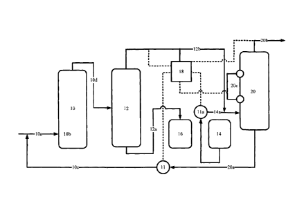
distribution system. Generally, in order to meet governmental, technical and
natural gas
sales specifications, H2S concentrations must be at very low levels (usually
less than 16
ppm).
[0003] Hydrogen sulfide is a covalent hydride structurally related to water
(H20) as
oxygen and sulfur occur in the same periodic table group. However, hydrogen
sulfide is
weakly acidic, dissociating in aqueous solution into hydrogen cations H+ and
the
hydrosulfide anion HS-:
H2S -> HS- + H+
[0004] Hydrogen sulfide reacts with many metals cations to produce the
corresponding
metal sulfides.
[0005] In petroleum refineries, the normal hydrodesulfurization processes
liberate sulfur
from petroleum by the action of hydrogen. The resulting H2S is converted to
elemental
sulfur by partial combustion via the Claus process, which is a major source of
elemental
sulfur.
-1-
CA 02641278 2008-10-17
[0006] The most highly utilized processes for sweetening sour natural gas is
to use
amine solutions to remove the hydrogen sulfide. These processes are known
simply as
the 'amine processes', or alternatively as the Girdler process, and are used
in 95 percent
of North American gas sweetening operations. Generally, the sour gas is run
through a
tower, which contains the amine solution. This solution has an affinity for
sulfur, and
absorbs it much like glycol absorbing water. There are several amine solutions
that are
commonly used, including monoethanolamine (MEA), methyldiethanolamine (MDEA),
and diethanolamine (DEA) each of which in their liquid form, will absorb
sulfur
compounds from natural gas as it passes through the column. The effluent gas
or sweet
gas is virtually free of H2S compounds. Like the process for NGL extraction
and glycol
dehydration, the amine solution used can be regenerated (that is, the absorbed
sulfur is
removed), allowing it to be reused to treat more sour gas. This technology is
capital
intensive and is generally more suitable for larger scale operations.
[0007] In other systems, the use of liquid scavengers within columns is also
known. In
these systems, sour gas and a liquid scavenger agent are introduced into a
column. The
scavenger reacts with sour gas within the column such that both sweet gas and
"spent"
scavenger are removed from the top of the column. The most common liquid
scavenger
is an amine-aldehyde condensate manufactured by an exothermic reaction of
monoethanolamine and formaldehyde. Water and methanol are usually required to
keep
the formaldehyde in solution and prevent polymerization. The resulting
"scavenger"
product is a hexahydrotriazine, and is commonly called "triazine" in the
industry. The
"triazine" is typically offered in a water-based solution. In most
applications, the reaction
products are also water soluble, with very low toxicity characteristics making
this a
relatively simple system to handle. Other scavenging reagents are known to
those
skilled in the art.
[0008] Importantly, the scavenging reactions between triazine and H2S can be
"overspent" such that the reaction products are solids. Generally, it is
preferred that solid
reaction products are not produced for ease of subsequent handling. Thus, most
reactions are controlled to underutilize the scavenging reagent.
[0009] While the liquid scavenger system is a relatively cost effective system
as a result
of the relatively low capital cost of equipment, simple logistics, and simple
waste
treatment, the cost of scavenger reagent is relatively high. Typically, as a
result of the
-2-
CA 02641278 2008-10-17
cost of the liquid scavenger, the overall process cost of H2S removal will
range from a
low of $8/pound to $20/pound of H2S removed. Notwithstanding the cost of
reagent, the
liquid scavenger system is a preferred system for offshore gas treatment and
onshore
sites where there is a relatively small amount of H2S that needs to be
treated.
[0010] However, there continues to be a need for a technology that improves
the
efficiency of utilization of scavenger reagent, such that the overall process
economics
can be improved.
SUMMARY OF THE INVENTION
[0011] In accordance with the invention, there is provided a system and method
for
improving the efficiency of utilization of scavenger chemical reagent in a
sour gas
treatment process.
[0012] In a first embodiment, the invention provides a system for removing
hydrogen
sulfide from natural gas comprising: a first reactor for reacting a partially-
consumed
scavenging reagent with sour natural gas and for producing partially-sweetened
natural
gas; a separator operatively connected to the first reactor for separating
consumed
scavenging reagent from the partially-sweetened natural gas; a second reactor
operatively connected to the separator for reacting clean scavenging reagent
with the
partially-sweetened natural gas and for producing sweetened natural gas; a
scavenging
reagent delivery system operatively connected to the first reactor and second
reactor,
the scavenging reagent delivery system for delivering clean scavenging reagent
to the
second reactor and partially-consumed scavenging reagent to the first reactor;
and, a
control system for controlling the relative flow of scavenging reagent to the
first and
second reactors in response to the hydrogen sulfide concentration within the
partially-
sweetened natural gas.
[0013] In a further embodiment, the invention provides a method for removing
hydrogen
sulfide from natural gas comprising the following steps in any order: a)
reacting a
partially-consumed scavenging reagent with sour natural gas to produce a
partially-
sweetened natural gas and consumed scavenging reagent; b) separating consumed
scavenging reagent from the partially-sweetened natural gas; and, c) reacting
clean
-3-
CA 02641278 2008-10-17
scavenging reagent with the partially-sweetened natural gas to produce
sweetened
natural gas; wherein the clean scavenging reagent from step c) is used as
partially-
consumed scavenging reagent in step a).
BRIEF DESCRIPTION OF THE DRAWINGS
[0014] The invention is described by the following detailed description and
drawings
wherein:
Figure 1 is a schematic diagram of a hydrogen sulfide plant and polishing
system in accordance with the prior art;
Figure 2 is a schematic diagram of a hydrogen sulfide processing plant and
polishing system in accordance with the invention; and
Figure 2A is a schematic diagram of a hydrogen sulfide processing plant and
polishing system in accordance with an alternate embodiment of the invention.
DETAILED DESCRIPTION
[0015] In accordance with the invention and with reference to the figures,
embodiments
of a system and method for removing hydrogen sulfide from natural gas are
described.
[0016] The system and method improves the efficiency of scavenger reagent (SR)
utilization in typical hydrogen sulfide sweetening processes.
[0017] As shown in Figure 1 and in accordance with the prior art, a typical
hydrogen
sulfide treatment plant utilizing a scavenger reagent includes a primary
reactor (or
column) 10 and separator 12. Sour gas 10a is introduced at a low point 10b in
the
column together with SR 10c from a fresh SR source 14 by pump 11. The sour gas
and
SR pass upwardly through the column whereby the sour gas is sweetened and the
SR is
consumed as known to those skilled in the art. The sweetened gas and SR 10d
collectively pass over the top of the column and thereafter enter separator 12
whereby
the sweetened gas and liquid SR are separated on the basis of density. The
liquid SR is
-4-
CA 02641278 2008-10-17
removed from the bottom 12a of the separator and delivered to a spent reagent
tank 16
for disposal and the sweetened gas is removed from the top 12b of the
separator for
delivery. The system is controlled by an appropriate control and feed back
system 18 to
monitor the H2S concentration in the sweetened gas 12b and to control the flow
of SR to
the column 10 through pump 11.
[0018] In order for the sweetening reactions to proceed and to ensure that the
sweetened gas meets the appropriate regulatory standard for H2S removal, the
SR must
be added in significant excess to ensure that the H2S removal reaction
proceeds to
completion. As a result, due to normal fluctuations in the H2S concentration
entering the
column 10, and to provide an appropriate safety margin, significant amounts of
SR
delivered to the spent reagent tank 16 may be unreacted.
[0019] In accordance with the invention, and with reference to Figure 2, a
system to
improve the efficiency of SR utilization is provided. Generally, the primary
desulfurization
system 10, 12 is used with partially-consumed SR 20a to produce a "semi-sweet"
gas
12b and clean SR 14a is used to polish the semi-sweet gas 12b to produce a
sweet gas
20b. As a result, the system, by virtue of the use of clean SR in the final
polishing step
enables more effective control of the utilization of SR.
[0020] In accordance with the invention, the system as described in Figure 1
is modified
to include a polishing system 20 comprising a second column that functions
similarly to
column 10 with the exception that it is operated as a combined reactor and
separator. In
addition, the system introduces clean SR 14a directly to column 20 prior to
introduction
into column 10 and the system is controlled such that semi-sweet gas 12b is
introduced
into column 20. In addition, the system includes pump 11 a to deliver clean SR
to column
20 and the control system 18 is modified to balance the effective flow rates
through both
pumps 11, 11 a in response to the measured H2S concentration from separator
12,
reagent levels in column 20 as measured by level controller 20c and in the
produced
sweetened gas.
[0021] Generally, the control system operates to ensure that the H2S
concentration
exiting column 20 is low (generally less than 16 ppm, ideally 0 ppm). Primary
control of
the system is by conducted on the basis of the measured H2S level between
separator
12 and column 20. For example, for a given set of operating parameters (i.e.
based on
-5-
CA 02641278 2008-10-17
the H2S levels, system volumes and stoichiometry of the specific system), the
system
may be designed such that the measured H2S level in semi-sweet gas 12b is in
the
range of 10-100 ppm in order that a desired H2S level of the sweet gas is at
the desired
level (ideally 0 ppm). As such, if the control system determines that the H2S
level is
within this range, pumps 11 and 11a will in turn be run at a given flow rate.
If the H2S
level is detected to be above this range, indicating a possible spike in H2S
level in the
source gas, the control system will increase flow rates through pumps 11, 11 a
so as to
increase the flow of SR within the columns. Similarly, a decrease in H2S level
below this
range, will cause a decrease in flow rates through pumps 11, 11 a so as to
reduce the
flow of SR in the columns. Readings of H2S concentrations in the sweet gas 20b
and
source gas 10a may be made for safety purposes and reference points but are
generally
not required for system control after the system is operating.
[0022] By way of representative example, the control system and the balance of
SR is
described as follows: If the semi-sweet gas 12b is 95% desulfurized in column
10, the
remaining 5% of the H2S is removed by reacting the semi-sweet gas with clean
SR in
column 20. The clean SR ensures that the desulfurization reactions in column
20
proceed to effectively 100% completion whilst depleting only 5% of the
desulfurization
capacity of the specific volume of clean SR. The partially-consumed SR 20a is
introduced into column 10 at a flow rate that ensures the complete utilization
of SR to
produce semi-sweet gas 12b. By responding to changes in the H2S concentration
in
semi-sweet gas 12b, the controller 18 can adjust the relative flow rates of SR
between
columns 10 and 20 and the level of SR within column 20. As a result, the
system can be
controlled to more effectively ensure complete utilization of SR whilst
producing sweet
gas. Thus, depleted SR entering tank 16 is fully depleted.
[0023] In a further embodiment as shown in Figure 2A, partially consumed SR
20a is
returned to tank 14a prior to pumping to column 10. From a practical
perspective, this
configuration may be preferred in the field particularly if the system is
being retro-fit to a
system in accordance with the prior art.
[0024] As a result, the system is able to effectively utilize SR without the
shortcomings
of the prior art by specifically being able to fully utilize the SR.
-6-
CA 02641278 2008-10-17
Example
[0025] A cost comparison between the prior art and the subject process is
detailed in
Table 1 for a triazine SR under the stated operating conditions. It is
understood that
specific operating conditions will vary depending on the numerous variables
including
vessel sizes, operating pressures and temperature and gas source as may be
established for or measured at a particular site.
Table 1- Cost Comparison at Representative Operating Conditions
Operating Conditions
Design Pressure 1440 psia
O eratin Pressure 300 psia
O eratin Temp 90 F
Gas Flow 1.0 MMscfd
H2S Inlet 2400 ppm
H2S Outlet 0 ppm
Scaven in Reagent Triazine
Scavenging Rate 0.2 L/ppm/MMscfd
(100%)
Cost Comparison
Parameter Subject Process Prior Art Process
System Efficiency 100% 80%
Scaven in Rate 0.2I/ m/MMscf 0.25I/ m/MMscf
Daily Chemical Use 480 I/day 600 I/day
Cost/Liter 3 $/liter 3 $/Iiter
Daily Chemical Cost 1440 $/day 1800 $/day
Process Cost 1.44 $/Mcf 1.8 $/Mcf
Changeout/fill fre uenc 67 Days 53 Days
Chan eout er ear 5.5 Fills/year 7 Fills/ ear
Annual Chemical Cost $525,000/year $657,000 $/year
Annual Savings $131,400/year
[0026] As shown, it is clear that based on the efficiency of fully using the
SR, significant
costs savings can be realized with the subject technology for a typical sour
gas well.
[0027] Although the present invention has been described and illustrated with
respect to
preferred embodiments and preferred uses thereof, it is not to be so limited
since
modifications and changes can be made therein which are within the full,
intended scope
of the invention.
-7-