Note: Descriptions are shown in the official language in which they were submitted.
CA 02641293 2008-10-17
TITLE: TURBO-GUIDING TYPE COOLING APPARATUS
BACKGROUND OF THE INVENTION
1. Field of the Invention
The invention relates to a turbo-guiding type cooling apparatus, and more
particularly to a structure that includes a reverse fixed blade unit and a
reduction cover between a heat sink and a fan.
2. Description of the Related Art
As shown in FIGS. 1 and 2, a conventional cooling apparatus 10 applied to
CPU or other electronic chips includes a heat sink 11 having a plurality of
fins
and an axial flow fan 12 disposed at the top of the heat sink 11. The bottom
of
the heat sink 11 lies on the surface of the electronic chip (or heat source
14).
After the operation of the fan 12, the heat energy of the heat source 14 can
be
transmitted to all fins of the heat sink 11 by use of the heat conduction.
Meanwhile, the cool air generated by the fan 12 is delivered to the fins of
the
heat sink 11 for conducting the heat exchange. In the way, the heat energy is
removed.
However, the conventional fan 12 belongs to an axial flow type. All of
blades 122 of the fan 12 are extended outward from a shaft portion 121 at the
center thereof. Many components like motor are received within the shaft
portion 121. Therefore, the shaft portion 121 occupies a considerable space.
The area adjacent to the heat zone 15 under the shaft portion 121 obtains less
cooling air when the fan 12 is operated. In other words, the cooling fins at
the
area of the heat zone 15 can hardly achieve the heat removal by cool air.
I
CA 02641293 2008-10-17
[
Moreover, the heat source 14 is aligned to the shaft portion 121 of the fan 12
when the cooling apparatus 10 is installed. Therefore, the current of air and
the
wind pressure generated by the fan 12 can not be transmitted to the heat zone
15 of the heat sink 11 most adjacent to the heat source 14. Therefore, the
heat-removal efficiency is reduced.
As shown in FIGS. 3 and 4, another conventional cooling apparatus 10a
includes an inclined and conic wind-guiding ring 13 between a heat sink 11 and
a fan 12. The wind-guiding ring 13 is provided for delivering the current of
air
generated by the fan 12 to a region covered by the shaft portion 121 at the
center of the fan 12 such that the cooling air can reach the part of the heat
sink
11 most adjacent to the heat source 14. It is expected to enhance the
heat-removal efficiency. This structure is disclosed by TW M259469.
It is correct for the above-mentioned cooling apparatus l0a to deliver the
current of air to the center. However, the effect achieved by the inclined and
conic wind-guiding ring 13 can be very limited since it can only achieve a
slight change of wind-delivering angle. Likewise, the cooling air can hardly
reach the view field (w) under the shaft portion 121, that is, the position of
the
heat source 14. Thus, the heat-removal efficiency can't be considerably
enhanced as well, and this requires further improvement.
As shown in FIG. 5, a further cooling apparatus 10b includes heat-removal
fins 16 in a vertical arrangement. It is different from the above-mentioned
heat-removal fins 16 in a horizontal arrangement. No maiter if the cooling
apparatus is in a horizontal arrangement or in a vertical arrangement, they
all
have the above-mentioned problem with respect to the heat removal.
2
CA 02641293 2008-10-17
The turbo-supercharging principle has been widely applied to many
pneumatic products, such as suction opening of the jet engine, accelerator for
automotive engines, particle vacuum pumps, etc. The operating principle of
these devices lies in that the rotary blades and the reverse blades fixed at
the
rim are assembled to be a blade unit. The high-speed rotary blades delivers
current of air to the reverse blades fixed at the rim such that the airflow
pressure
can be rapidly enhanced between the rotary blades and the reverse blades fixed
at the rim. This is the principle of the well-known turbo-supercharging
process.
Many cooling fans or ventilators are provided with the turbine device.
However, most of them only combine one turbine fan and the cooling fins or
employ a fan blowing to a reverse eddy-shaped and non-bladeshaped partitions
regularly spaced. The turbo-supercharging structure occupies a greater space
and is aimed to enhance the wind pressure. However, this can cause a power
loss due to return pressure created by these cooling apparatuses.
Consequently,
these conventional apparatuses are not applicable.
SUMMARY OF THE INVENTION
A primary object of the invention is to provide a turbo-guiding type
cooling apparatus that smoothly delivers the current of air generated by a fan
to
a heat sink such that a heat exchange takes place in a heat region where the
current of air within the heat sink does not reach easily. In other words, the
heat
region can be cooled by the injected current of air such that the heat energy
can
be smoothly removed for enhancing the heat-removal efficiency.
Another object of the invention is to provide a turbo-guiding type cooling
3
CA 02641293 2008-10-17
apparatus that ensures an extended service life of electronic chips and
increases
their reliability. Moreover, the heat-removal volume is diminished for saving
precious space. Meanwhile, an unnecessary material waste is avoided. In
addition, it is not necessary to use high-speed fan so that the noise can be
reduced.
In order to achieve the above-mentioned objects, the invention has the
following features:
A reverse fixed blade unit is interposed between the wind exit surface of
the fan and the heat sink. The rotation direction of the reverse fixed blade
unit is
opposite to that of the fan. A receiving chamber is formed under the shaft of
the reverse fixed blade unit, and the receiving chamber has at least one-third
height of the reverse fixed blade unit.
A separation portion extending into the receiving chamber is formed at the
center of the top of at least one part of the heat sink.
The reverse fixed blade unit includes a reduction cover inward tapered at
the periphery of the wind outlet thereof. The height (h 1) of the periphery of
the
reduction cover is the same to or greater than the height (h2) of the
periphery of
the wind outlet of the reverse fixed blade unit, thereby forming a ring-shaped
enclosing type. Therefore, the wind will be smoothly concentrated and the
flow direction will be changed. Meanwhile, each of the airflows will be
separated by the separation portion and delivered to the heat source of the
heat
sink.
Based on the above-mentioned features, the turbo-guiding type cooling
apparatus includes a reverse fixed blade unit and a reduction cover. A
4
CA 02641293 2008-10-17
receiving chamber is formed under the shaft of the reverse fixed blade unit
into
which the separation portion is extended. In this way, a concentrated airflow
can be delivered to the front side of a heat region of the cooling fins. The
idea
of smooth guiding of the airflow and the structure appearance is partially
similar to the turbo-supercharging principle. The main feature of the
invention
lies in "diversion" (flow-guiding). In other words, the reverse fixed blade
unit
within the reduction cover, the flow-guiding chamber under the shaft, and the
extending reduction cover are well employed for conducting the flow-guiding
task. Therefore, it is not necessary for the invention to have a high rotation
speed required by the turbine. Meanwhile, components such as coupling und
gear mechanism are also not required for pressure rise. This feature is
therefore
called as "turbo-guiding" that shows a distinct difference from the
conventional
"turbo-sup ercharging" .
The configuration of the reverse fixed blade unit and the reduction cover is
simple and can achieve the heat-removal effect. In this way, the whole volume
can be so properly reduced that the dimensions of the entire cooling apparatus
won't be increased to occupy much space. It is therefore beneficial to arrange
electronic components in the computer. The reverse fixed blade unit of the
invention can be disposed within an independent mounting frame as the need
arises. Alternatively, it can be designed to be a turbo-guiding type fan that
is
combined with a reduction cover and a heat-conducting module. In addition, it
can be integrally formed with the fins of the heat sink.
No matter which of the above-mentioned embodiments is applied, a
concentrated current of air directed to the heat source can be obtained.
5
CA 02641293 2008-10-17
Meanwhile, the vibration and the noise generated by wind pressure can be
avoided. Moreover, an optimal value of wind pressure and wind quantity can
be obtained without problem under the condition of the least power loss,
thereby optimizing the heat-removal efficiency. Thus, the invention can
eliminate the problem of the conventional heat sink and is really an effective
cooling apparatus applicable in the electronic industry.
BRIEF DESCRIPTION OF THE DRAWINGS
The accomplishment of this and other objects of the invention will become
apparent from the following descriptions and its accompanying figures of
which:
FIG. 1 is an exploded perspective view of a conventional horizontal type
cooling apparatus;
FIG. 2 is a cross-sectional view of the conventional horizontal type
cooling apparatus after assembly;
FIG. 3 is an exploded perspective view of another conventional horizontal
type cooling apparatus;
FIG. 4is a cross-sectional view of another conventional horizontal type
cooling apparatus after assembly;
FIG. 5 is a schematic drawing of a conventional vertical type cooling
apparatus;
FIG. 6 is an exploded perspective view of a first embodiment of the
invention;
FIG. 7is a cross-sectional view of the first embodiment of the invention;
FIG. 8 is a perspective view of a second embodiment of the invention;
6
CA 02641293 2008-10-17
FIG. 9 is a perspective view of a third embodiment of the invention;
FIG. 10 is an exploded perspective view of a fourth embodiment of the
invention;
FIG. 11 is an exploded perspective view of a fifth embodiment of the
invention;
FIG. 12A is a top view of a vertical type cooling fins in FIG. 11;
FIG. 12B is a cross-sectional view taken along the line 12B-12B in FIG.
12A;
FIG. 13A is a top view of a reduction cover in FIG. 11;
FIG. 13B is a cross-sectional view taken along the line 13B-13B in FIG.
13A;
FIG. 14A is a top view of a reverse fixed blade unit 40 in FIG. 11;
FIG. 14B is a cross-sectional view taken along the line 14B-14B in FIG.
14A;
FIG. 14C is a cross-sectional view taken along the line 14C-14C in FIG.
14A;
FIG. 15A and 15B are cross-sectional views of the embodiment in FIG.
11;
FIG. 16 is a perspective view of a sixth embodiment of the invention;
FIG. 17 is an exploded cutaway view of the sixth embodiment of the
invention;
FIG. 18 is a cutaway view of a seventh embodiment of the invention after
assembly;
FIG. 19 is an exploded perspective view of the seventh embodiment of the
~
CA 02641293 2008-10-17
invention;
FIG. 20 is a perspective view of the seventh embodiment of the invention
after assembly;
FIG. 21 is an exploded perspective view of an eighth embodiment of the
invention;
FIG. 22 is an assembly perspective view of partial components of the
eighth embodiment of the invention; and
FIG. 23 is a cutaway view of the eighth embodiment of the invention.
DETAILED DESCRIPTION OF THE PREFERRED EMBODIMENT
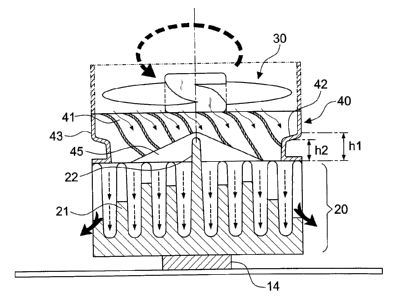
First of all, referring to FIGS. 6 and 7, a turbo-guiding type cooling
apparatus in accordance with the invention includes a heat sink 20, and a fan
30.
The heat sink 20 includes a plurality of horizontal type cooling fins 21.
According to the embodiment, the heat sink 20 belongs to a horizontal type
heat sink. It should not be restricted thereto. The configuration of the
invention can be also applied to the vertical type heat sink or heat-
conducting
module. These will be descried in detail hereinafter. The heat sink 20 is not
the
object of the invention so that no further descriptions thereto are given
hereinafter.
The fan 30 is disposed at the top of the heat sink 20. According to the
invention, the fan 30 is an axial-flow fan so that the heat exchange takes
place
by delivering cool air downward to the heat sink 20.
The invention features a reverse fixed blade unit 40 interposed between
the wind exit surface of the fan 30 and the heat sink 20. The rotation
direction
8
CA 02641293 2008-10-17
of the reverse fixed blade unit 40 is opposite to that of the fan 30. A
receiving
chamber 45 is formed under the shaft of the reverse fixed blade unit 40. The
receiving chamber 45 must have at least one-third height of the reverse fixed
blade unit 40. Two-third height thereof or more than two-third height thereof
is
preferred.
A separation portion 22 extending into the receiving chamber 45 is formed
at the center of the top of the heat sink 20.
The reverse fixed blade unit 40 includes a reduction cover 42 inward
tapered at the periphery of the wind outlet thereof. The height h 1 of the
periphery of the reduction cover 42 is the same to or greater than the height
h2
of the periphery of the wind outlet of the reverse fixed blade unit 40,
thereby
forming a ring-shaped enclosing type. In this way, the wind will be smoothly
concentrated and the flow direction will be changed. Meanwhile, each of the
air flows will be separated by the separation portion 22 and delivered to the
heat source of the heat sink 20.
According to the embodiment of the invention, the separation portion 22
includes projecting fins. There are one or several fins depending on the
requirements.
In order to gather up the air flow and then to deliver it to the heat source,
the fan 30 is employed to replace the conventional turbo-supercharging and
super high-speed shaft blade. Moreover, the shape, the number of blades and
the gap of the reverse fixed blade unit 40 must be designed according to the
rotation speed of the fan 30 and the blade shape for achieving the flow-
guiding
effect.
9
CA 02641293 2008-10-17
Based on such the above-mentioned combination, the shaft of the reverse
fixed blade unit 40 serves as wind outlet and is enclosed by the reduction
cover
42 at the ring side. In this way, the airflow can be smoothly gathered
together
by means of the eddy guide. Besides, each of the airflows can be separated by
means of the separation portion 22 extending to the bottom of the shaft of the
reverse fixed blade unit 40. Meanwhile, the airflows are delivered to the heat
source. The object of the invention lies in the smooth diversion rather than
the
conventional turbo-supercharging process for increasing the wind pressure. In
other words, the main effect of the invention is the gathering of the wind
amount. The increase of the wind pressure is not the object of the invention.
Based on the above-mentioned means, the invention includes the
following embodiments.
First of all, referring to FIG. 8, the reverse fixed blade unit 40 is disposed
within an independent mounting frame 43 in such a way that it serves as a
connection base for the fan 30 and the heat sink 20. In other words, the
structure is created by assembling the above-mentioned three individual
components one after the other.
As shown in FIG. 9, which illustrates another embodiment of the reverse
fixed blade unit 40, vertical fins 23 of the heat sink 20a are integrally
formed
with the reverse fixed blade unit 40 so as to create a turbo-guiding type
cooling
apparatus 60. Thereafter, the fan 30 is installed thereon. This embodiment is
more suitable for the vertical type cooling apparatus. Vortex type blades 41
can be directly formed by bending the upper portion of the vertical fins 23
counterclockwise or clockwise. A blade socket 44 is mounted at the periphery
CA 02641293 2008-10-17
of the blades 41. In this way, the reverse fixed blade unit 40 and the heat
sink
20a are integrally combined for different application requirements.
Based on the above-mentioned features, a preferred application is shown
in FIGS. 10 through 16. The same components are marked with the same
reference sign. The difference between FIG. 10 and 11 lies only in that the
tapered portion 421of the reduction cover 42a in FIG. 10 is an substantially
arched body without recesses while the tapered portion 421 of the reduction
cover 42a in FIG. 11 includes radial recesses 422. The other parts are the
same.
The embodiment of the invention according to FIGS. 11 through 15 includes a
heat sink 20a consisting of a plurality of vertical fins 23 and a fan 30
disposed
at the top of the heat sink 20a.
The invention features a reverse fixed blade unit 40 interposed between
the wind exit surface of the fan 30 and the heat sink 20a. The rotation
direction
of the reverse fixed blade unit 40 is opposite to that of the fan 30. As shown
in
FIG. 14C, A receiving chamber 45 is formed under a shaft 411 of the reverse
fixed blade unit 40. The receiving chamber 45 must have at least one-third
height of the reverse fixed blade unit 40. Moreover, a mounting frame 43 and a
shaft 411 are attached to the reverse fixed blade unit 40 for installing the
fan 30
thereon.
The heat sink 20a consists of a plurality of vertical fins 23 arranged in a
radiating manner. The heat sink 20a includes a ring groove 231 and a middle
hole 232. Meanwhile, a projecting separation portion 22a extending into the
receiving chamber 45 is formed at the ring groove 231 facing the middle hole
232. According to the embodiment, the separation portion 22a is an inclined
11
CA 02641293 2008-10-17
cone created by the central part of the vertical fins 23.
A reduction cover 42a is interposed between the heat sink 20a and the
reverse fixed blade unit 40. The reduction cover 42a has an inward tapered
portion 421. The center thereof is hollow to create a wind outlet 424. The
tapered portion 421 lies at the periphery of the ring groove 231 of the
vertical
fins 23. The height hl of the periphery of the cover is the same to or greater
than the height h2 of the periphery of the wind outlet of the reverse fixed
blade
unit 40, thereby forming a ring-shaped enclosing type. In this way, the wind
will be smoothly concentrated and the flow direction will be changed.
Meanwhile, each of the air flows will be separated by the separation portion
22a and delivered to the heat source of the heat sink 20.
As shown in FIGS. 11, 14A-14C, the mounting frame 43 of the reverse
fixed blade unit 40 further includes a shaft 411 at the center thereof for
fixing
the fan 30 in place.
Besides, a ring groove 231 and a middle hole 232 are illustrated in FIGS.
12A and 12B. Meanwhile, several vertical fins 23 are extended outward to
create a screw connection portion 233.
FIGS. 13A and 13B are a top view and a cutaway view of the reduction
cover 42a in FIG. 11. As shown in FIGS. 15A and 15B, the heat sink 20a, the
reduction cover 42a, the reverse fixed blade unit 40, and the fan 30 are
assembled to create a turbo-guiding type cooling apparatus 70. The feature of
this embodiment is the same to that of the previous embodiments. Moreover,
the spacial assembly structure is more concrete. The screw connection portions
233, 423 of the heat sink 20, the reduction cover 42a, and the mounting frame
12
CA 02641293 2008-10-17
43 can be fixed by screws (not shown) or other elements to complete the
assembly. In addition, a heat-conducting module 24 is formed at the bottom of
the middle hole 232 of the heat sink 20a for enhancing the heat-removal
effect.
As shown in FIG. 10, the reduction cover 42a has a tapered portion 421
without recesses. The arched body is disposed at the periphery of the ring
groove 231 of the vertical fins 23. As shown in FIG. 11, radial recesses 422
are
present for the insertion of the tapered portion 421 into the vertical fins
23.
These two embodiments are also formed in a ring-shaped enclosing type.
As shown in FIGS. 16 and 17, the top of the mounting frame 43 is flat and
has no room for mounting the fan 30 in place. Therefore, an independent
mounting base 31 is disposed at the top of the mounting frame and fitted with
a
shaft 411 at the center thereof for mounting the fan 30 in place. Thereafter,
the
combination body is fixed on the mounting frame 43. The other components
are the same to that of the previous embodiments so that no further
descriptions
thereto are given hereinafter.
As shown in FIGS. 18 through 20, the heat sink 20a, the reverse fixed
blade unit 40, and the reduction cover 42a are integrally formed. The features
thereof substantially correspond to that in FIG. 9. The periphery of the
blades
41 in FIG. 9 includes a blade socket 44, and the reduction cover 42 is
disposed
at the bottom of the blade socket 44. According to this embodiment, the vortex
type blades 41 of the reverse fixed blade unit 40 are directly formed at the
reduction cover 42a. Meanwhile, the tapered portion 421 of the reduction
cover 42a is also formed in the gaps between the cooling fins 21. The heat
sink
20a, the reverse fixed blade unit 40, and the reduction cover 42a are
integrally
13
CA 02641293 2008-10-17
formed by an integral module 80 that is made by a plurality of the metal
pieces
in stamping and bending process. Meanwhile, fixing elements 81 are
employed to combine them in an integral structure. Meanwhile, the fan 30 is
mounted within a mounting base 31 and then disposed on the heat sink 20a by
several screws 33 extending through the screw connection portions 311, 233.
According to this embodiment, an integral module 80 is employed for a
convenient assembly of the mounting base 31 of the conventional fan 30.
Therefore, this embodiment is different from the previous embodiment only in
the assembly and processing way. The other structure and features are the
same to that of the other embodiment so that no further descriptions thereto
are
given hereinafter.
FIGS. 21 through 23 illustrate a further embodiment of the invention. The
same components are marked with the same reference signs. The difference is
detailed hereinafter.
The heat sink is a heat-conducting module 20b. According to a preferred
embodiment, the periphery is formed in a conic and arched shape. A projecting
separation portion 22a extending into the receiving chamber 45 is disposed at
the top of the heat sink 20b. Meanwhile, several radial recesses 25 are formed
in the conic surface of the heat sink 20b.
As for the reduction cover 42a, the tapered portion 421 thereof does not
have recesses. However, several straight fins 425 are provided at the wind
outlet 424 for engaging into radial recesses 25 of the heat sink 20b.
According
to a preferred embodiment, the straight fin 425 has a connection surface 426
in
the middle thereof and is fixed by a screw 427 fitting into a connection hole
26
14
CA 02641293 2008-10-17
at the top of the heat sink 20b. Likewise, the height h 1 of the periphery of
the
reduction cover 42a is the same to or greater than the height h2 of the
periphery
of the wind outlet of the reverse fixed blade unit 40, thereby forming a
ring-shaped enclosing type. The function is the same to that of the previous
embodiments so that no further descriptions thereto are given hereinafter.
According to the above-mentioned embodiments, a few common features
are concluded as follows:
1. A receiving chamber 45 extending to the bottom over more than
one-third height thereof is formed under the shaft of the reverse fixed blade
unit
40. Preferably, the receiving chamber 45 is extended from the periphery to the
center thereof in an inclined type.
2. No matter if the heat sink consists of fins or is formed by a
heat-conducting module, a projecting separation portion 22, 22a extending to
the receiving chamber 45 is formed at the center of the heat sink for
separating
different airflows.
3. The reverse fixed blade unit 40 includes an enclosing reduction cover 42,
42a at the periphery of the wind outlet thereof. The height hl of the
periphery
of the reduction cover is the same to or greater than the height h2 of the
periphery of the wind outlet of the reverse fixed blade unit 40 In this way,
the
wind will be smoothly delivered to the heat source of the heat sink 20.
Moreover, the reduction cover is provided with recesses or without recesses
for
an easy connection to the heat sink. Of course, the reduction cover can be
integrally formed with the heat sink in a stamping process. Furthermore, the
fins 425 are provided for a direct connection with the heat-conducting module
CA 02641293 2008-10-17
20b. Therefore, the above-mentioned variations are within the scope of the
invention and can fulfill the requirement of the heat-removal efficiency.
Many changes and modifications in the above-descried embodiments of
the invention can, of course, be carried out without departing from the scope
thereof Accordingly, to promote the progress in science and the useful arts,
the invention is disclosed and is intended to be limited only by the scope of
the
appended claims.
16