Language selection

Search

Patent 2641368 Summary

Third-party information liability

Some of the information on this Web page has been provided by external sources. The Government of Canada is not responsible for the accuracy, reliability or currency of the information supplied by external sources. Users wishing to rely upon this information should consult directly with the source of the information. Content provided by external sources is not subject to official languages, privacy and accessibility requirements.

Claims and Abstract availability

Any discrepancies in the text and image of the Claims and Abstract are due to differing posting times. Text of the Claims and Abstract are posted:

  • At the time the application is open to public inspection;
  • At the time of issue of the patent (grant).
(12) Patent Application: (11) CA 2641368
(54) English Title: SOCK DONNING DEVICE
(54) French Title: DISPOSITIF D'ENFILAGE DE CHAUSSETTES
Status: Dead
Bibliographic Data
(51) International Patent Classification (IPC):
  • A47G 25/90 (2006.01)
  • A41F 13/00 (2006.01)
  • A47G 25/80 (2006.01)
(72) Inventors :
  • SCHOEPE, ERICH G. (Canada)
(73) Owners :
  • SCHOEPE, ERICH G. (Canada)
(71) Applicants :
  • SCHOEPE, ERICH G. (Canada)
(74) Agent: OSLER, HOSKIN & HARCOURT LLP
(74) Associate agent:
(45) Issued:
(22) Filed Date: 2008-10-21
(41) Open to Public Inspection: 2009-05-09
Examination requested: 2008-11-06
Availability of licence: N/A
(25) Language of filing: English

Patent Cooperation Treaty (PCT): No

(30) Application Priority Data:
Application No. Country/Territory Date
60/996,315 United States of America 2007-11-09
12/230,171 United States of America 2008-08-25

Abstracts

English Abstract


The sock donning device is an apparatus that allows an individual of
limited ability of movement to put on a sock. The device includes a pair of
laterally spaced, hinged, telescoping rods that are connected to a
substantially ovoid or circular hoop assembly, with rollers positioned about
its circumference. The device is mounted to a base that may be made from
wood or similar material. The rollers and hoop assembly hold an upper
portion of the sock open as the user inserts his or her feet into the sock.


Claims

Note: Claims are shown in the official language in which they were submitted.


CLAIMS

I claim:


1. A sock donning device, comprising:
a base;

a plurality of rods extending from the base;
a hoop assembly mounted on the rods; and

a plurality of rollers mounted on the hoop assembly, the hoop
assembly being adapted for supporting a sock in an open position.


2. The sock donning device as recited in claim 1, wherein said base is
substantially rectangular.


3. The sock donning device as recited in claim 2, wherein rods extend
along a lateral axis of said base.


4. The sock donning device as recited in claim 1, further comprising a
layer of textured material having a high coefficient of friction at least
partially
covering said base.


8


5. The sock donning device as recited in claim 1, wherein said rods
are telescopic rods having a selectively adjustable length.

6. The sock donning device as recited in claim 1, wherein said rods
are pivotally attached to said base.

7. The sock donning device as recited in claim 1, further comprising a
hinged bracket mounted on said base, said rods being attached to the hinge
in order to pivot thereon.

8. The sock donning device as recited in claim 7, wherein the hinged
bracket is pivotally attached to said base, the hinged bracket pivoting about
a vertical axis.

9. The sock donning device as recited in claim 1, wherein said plurality
of rollers comprise a plurality of substantially spherical beads.


9


10. A sock donning device, comprising:
a base;

a plurality of telescoping rods attached to the base; and
means for supporting a sock on the telescoping rods.

11. The sock donning device as recited in claim 10, wherein said
means for supporting the upper portion of the sock on the at least one
telescoping rod comprises:

a hoop assembly mounted on an upper end of the at least one rod; and
a plurality of rollers mounted on the hoop assembly, the hoop
assembly and the plurality of rollers being adapted for supporting an upper
portion of the sock in an open position for insertion of a user's foot
therein.

12. The sock donning device as recited in claim 11, wherein said
plurality of rollers comprise a plurality of substantially spherical beads.

13. The sock donning device as recited in claim 10, wherein said base
is substantially rectangular.


14. The sock donning device as recited in claim 10, wherein said
telescoping rods extend along a lateral axis of said base.

15. The sock donning device as recited in claim 10, wherein said
telescoping rods extend along a longitudinal axis of said base.

16. The sock donning device as recited in claim 10, further comprising
a layer of textured material having a high coefficient of friction at least
partially covering said base.

17. The sock donning device as recited in claim 12, wherein said rods
are pivotally attached to said base.

18. A sock donning device, comprising:
a base;

a plurality of telescoping rods pivotally attached to the base;
a hoop assembly mounted on the rods; and

a plurality of rollers mounted on the hoop assembly, the hoop
assembly being adapted for supporting a sock in an open position.


11


19. The sock donning device as recited in claim 18, further comprising
a layer of textured material having a high coefficient of friction disposed on

said base.

20. The sock donning device as recited in claim 18, further comprising
a hinge pivotally attached to said base, the hinge pivoting about a vertical
axis, the rods being pivotally mounted on the hinge, the rods pivotal about a
horizontal axis through an arc of about 45°.


12

Description

Note: Descriptions are shown in the official language in which they were submitted.


CA 02641368 2008-10-21

SOCK DONNING DEVICE
BACKGROUND OF THE INVENTION
1. FIELD OF THE INVENTION

[00011 The present invention relates to garment applicators, and
particularly to a sock donning device that allows an individual to put a sock
or
stocking on his or her foot without the necessity of bending over.

2. DESCRIPTION OF THE RELATED ART

[0002] Many persons suffer from disabilities that prevent them from
bending over without either pain or the risk of injury. Persons suffering from
arthritis, rheumatism and other joint ailments, inner ear and other
equilibrium
problems, or simply individuals suffering from various infirmities of old age
can
find that the contortions required to put on a stocking or sock are beyond
their
physical abilities. Women who are in the later stages of pregnancy often
cannot
bend without extreme discomfort or are physically unable to bend at all.
Individuals so afflicted must either have assistance from caregivers or other
i


CA 02641368 2008-10-21

persons when putting on stockings, socks or other coverings for the foot, or
do
without.

[0003] Considering that it is often medically necessary for individuals with
circulatory or vascular problems to have appropriate socks or other foot
coverings, an inability to put on these items without assistance can have an
adverse effect on an individual's health, independence and emotional well
being. There is a need for a device that allows a person to put on a pair of
stockings or socks. Thus, a sock donning device solving the aforementioned
problems is desired.

SUMMARY OF THE INVENTION

[0004] The sock donning device is an apparatus that allows an individual
who may have limited movement because of injury, infirmity or other disability
to put on a sock or stocking without bending over. The device has a pair of
laterally spaced rods that are surmounted by an oval hoop assembly, with
rollers around the circumference of the hoop assembly.

[0005] The rods may be telescopic to accommodate various lengths of
stockings, and can be attached at their lower ends to a hinge that can swivel
2


CA 02641368 2008-10-21

45 from the vertical. Two non-slip surfaces on either side of the sock
donning
device provide a secure footrest and prevent the device from sliding while in
use. A sock or stocking is placed over the oval hoop assembly, and when the
foot is inserted into the sock, the surrounding beads roll the sock up and
over
the foot.

[0006] The sock donning device described herein provides a painless way
for a person who has limited movement to put on a sock or stocking without
assistance, and can accommodate both varying stocking lengths and varying
degrees of motion.

[0007] These and other features of the present invention will become
readily apparent upon further review of the following specification and
drawings.

3


CA 02641368 2008-10-21

BRIEF DESCRIPTION OF THE DRAWINGS

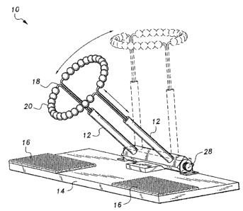
[0008] Fig. 1 is a perspective view of a sock donning device according to
the present invention.

[0009] Fig. 2 is an environmental prospective view of the sock donning
device according to the present invention, showing a sock placed on the
device.
[0010] Fig. 3 is an environmental perspective view of the sock donning
device according to the present invention similar to Fig. 2, showing a foot
being
inserted into the sock

[00111 Fig. 4 is an environmental perspective view of the sock donning
device of the present invention similar to Fig. 3, showing the sock in the
process of rolling up and over the foot as the foot is pushed into the device.
[0012] Fig. 5 is an environmental perspective view of the sock donning
device of the present invention similar to Figs. 3 and 4, showing the sock in
its
final position up and over the foot as the foot is fully extended through the
device.

[0013] Fig. 6 is a perspective view of an alternative embodiment of a sock
donning device according to the present invention.

4


CA 02641368 2008-10-21

[0014] Similar reference characters denote corresponding features
consistently throughout the attached drawings.

DETAILED DESCRIPTION OF THE PREFERRED EMBODIMENTS

[0015] The present invention relates to a sock donning device, generally
designated as 10 in the drawings, to help an individual with limited mobility
put
on a sock or stocking. Device 10 is particularly useful to those individuals
who,
due to injury or infirmity, find it difficult or impossible to achieve the
range of
motion required to pull a sock or stocking over the foot.

[0016] As shown in Fig. 1, the sock donning device 10 includes a pair of
laterally spaced rods 12 that are attached to a base 14. The base 14 can be
made from wood or other suitable materials. The base 14 also has two
textured surfaces 16 that may be made of rubber or other material, which are
mounted on each side of the top surface of the base 14 to provide a secure
place upon which to place the foot and prevent the sock donning device 10
from slipping while being used.

[0017] An oval or circular hoop assembly 18 is attached to the rods 12.
The hoop 18 includes rollers 20 disposed all around its circumference. Fig. 2


CA 02641368 2008-10-21

illustrates a sock or stocking in place over the circular hoop assembly 18.
Rollers 20 may be spherical beads or the like, which are free to rotate about
the
hoop 18.

[0018] In Fig. 3, the user's foot is shown being inserted into the sock, and
in Figs. 4 and 5, the rolling action of the rollers 20 causes the sock to be
rolled
up over the foot; i.e., as the user pushes his or her foot downward into the
sock, the upper portion of the sock, which is wound about rollers 20, unwinds
or unwraps, thus being pressed against the user's leg in the conventional
manner.

[0019] The rods 12 may be telescoping rods, as shown, allowing the
device to accommodate varying lengths of stockings and socks, and may be
pivotally attached to the base 14, allowing the rods 12 to pivot 45 from the
vertical. Hinge 28 is shown for exemplary purposes only. Rods 12 may be
pivotally attached to base 14 through any suitable pivotal attachment.

[0020] In the embodiment of Figs. 1 -5, the base 14 is substantially
rectangular, and rods 12 extend along the lateral axis thereof (the
longitudinal
axis being defined by the longer side of the rectangular base 14, and the
lateral
axis being defined by the shorter side of the rectangular base 14). In the
6


CA 02641368 2008-10-21

alternative embodiment of Fig. 6, sock donning device 100 includes a base 114,
which is also substantially rectangular (although base 114 may have any
desired shape or dimensions). However the telescoping rods 1 12 extend along
the longitudinal axis thereof. Textured portions 16 of Figs. 1 -5 are replaced
by
a single textured portion 116. Hoop 1 18 and rollers 120 are similar to hoop
18
and rollers 20 of the embodiment of Figs. 1 -5. Rods 112 are pivotally joined
to
base 114 through a hinged bracket 128, and hinged bracket 128 may be
pivotally attached to base 1 14 by pivot pin 130 or the like, allowing the
hinged
bracket 128 to rotate about the vertical axis, as indicated by the directional
arrow in Fig. 6.

[0021] It is to be understood that the present invention is not limited to
the embodiments described above, but encompasses any and all embodiments
within the scope of the following claims.

7

Representative Drawing
A single figure which represents the drawing illustrating the invention.
Administrative Status

For a clearer understanding of the status of the application/patent presented on this page, the site Disclaimer , as well as the definitions for Patent , Administrative Status , Maintenance Fee  and Payment History  should be consulted.

Administrative Status

Title Date
Forecasted Issue Date Unavailable
(22) Filed 2008-10-21
Examination Requested 2008-11-06
(41) Open to Public Inspection 2009-05-09
Dead Application 2011-10-21

Abandonment History

Abandonment Date Reason Reinstatement Date
2010-10-21 FAILURE TO PAY APPLICATION MAINTENANCE FEE

Payment History

Fee Type Anniversary Year Due Date Amount Paid Paid Date
Application Fee $200.00 2008-10-21
Request for Examination $400.00 2008-11-06
Owners on Record

Note: Records showing the ownership history in alphabetical order.

Current Owners on Record
SCHOEPE, ERICH G.
Past Owners on Record
None
Past Owners that do not appear in the "Owners on Record" listing will appear in other documentation within the application.
Documents

To view selected files, please enter reCAPTCHA code :


To view images, click a link in the Document Description column. To download the documents, select one or more checkboxes in the first column and then click the "Download Selected in PDF format (Zip Archive)" or the "Download Selected as Single PDF" button.

List of published and non-published patent-specific documents on the CPD .

If you have any difficulty accessing content, you can call the Client Service Centre at 1-866-997-1936 or send them an e-mail at CIPO Client Service Centre.


Document
Description 
Date
(yyyy-mm-dd) 
Number of pages   Size of Image (KB) 
Abstract 2008-10-21 1 13
Description 2008-10-21 7 168
Claims 2008-10-21 5 85
Drawings 2008-10-21 6 154
Representative Drawing 2009-04-16 1 20
Cover Page 2009-05-04 2 51
Assignment 2008-10-21 2 103
Prosecution-Amendment 2008-11-06 1 52