Note: Descriptions are shown in the official language in which they were submitted.
CA 02641504 2008-08-05
WO 2007/091001
PCT/GB2006/000415
-1-
BRAKING SYSTEMS WITH COOLING
This invention relates to braking systems
particularly, but not exclusively, for vehicle wheels.
Braking systems for vehicle wheels generally function
by converting kinetic energy into heat energy using a
braking system which includes a surface with a high
coefficient of friction to slow down the wheels. The
problem is that if the generated heat is not dissipated,
the braking efficiency of the systems becomes less and
less, and eventually the brakes fail through so-called
brake fade.
Drum brakes are particularly vulnerable to brake fade
because more of the drum is heated by the friction
generating shoes than is available to dissipate heat by
convection to the surrounding air.
Disc brakes are generally more efficient than drum
brakes because they enable greater pressure to be applied
by a calliper squeezing brake pads on to a brake disc
attached to the associated wheel hub than can be applied to
the internal surface of the drum of a drum brake. The area
of heating contact between the friction pads of disc brakes
and their associated discs can therefore be substantially
reduced compared with that of brake shoes with their
associated drums for the same braking effort. Typically,
20% of the surfaces of the discs of disc brakes are
intensely heated by disc pads, with 80% of the disc being
available to dissipate heat by convection to the
surrounding air within the confines of the associated
wheel.
In an attempt to improve their vehicle braking
systems, manufacturers have been increasing the internal
diameters of the wheels of their vehicles so that larger
diameter discs and larger brake callipers can be fitted.
This can enable the braking leverage of braking systems to
be increased as a result of the increased disc radius.
However, the larger radius of these larger discs means that
CA 02641504 2008-08-05
WO 2007/091001
PCT/GB2006/000415
- 2 -
the associated calliper has to be considerably longer than
with the conventional smaller discs to cover the depth of
the discs.
The longer so-called "beam" callipers used with these
larger discs are generally of four or six pot construction,
and this adds considerably to their complexity and cost of
production. In addition, they greatly reduce the area of
the brake disc which is exposed for cooling by convection
to air inside the wheel, and they can also worsen the
"plug" effect by reducing the air space available to cool
the discs by convection of air inside the associated wheel.
The main inherent problem with both drum and disc
braking systems is, therefore, that heat dissipation from
them by convection through the air alone is generally
insufficient to prevent brake fade. Furthermore, the very
designs of the braking systems themselves tend to reduce
their efficiency by disrupting airflow over surfaces which
should serve to cool these surfaces.
It is an object of the invention to provide a braking
system which can be cooled particularly well and exhibit
high and prolonged performance.
According to the invention there is provided a braking
system comprising an axle, a support element mounted on the
axle, a brake ring connected to the periphery of the
support element and a brake calliper for applying a braking
force to the brake ring, the brake ring being connected to
the support element in such a manner that a conductive heat
flow path is provided for conducting heat from the brake
ring into the support element and there being an airflow
path passing through the support element and through the
region in which the brake calliper is situated for
transferring heat by convection from the brake ring and the
brake calliper.
By cooling the braking arrangement both by conduction
of heat from the ring into the support element and by
convection cooling of the support element, the ring and the
brake calliper, it becomes possible to provide a braking
CA 02641504 2008-08-05
WO 2007/091001
PCT/GB2006/000415
- 3 -
system with good cooling and high performance, even with
prolonged braking.
The braking system may be applied to a wheel of a
vehicle, for example a car. The wheel may include a hub
and the support element. The support element may extend
from the hub to the brake ring. The brake ring may form
part of, or be connected to, the rim of the wheel.
Whilst it is within the scope of the invention to rely
on cooling air currents being generated by convection or
other factors, the braking system preferably includes air
current generating means for creating a flow of air along
the airflow path. For example, vanes may be provided for
creating the flow of air along the airflow path. The vanes
may form part of the support element. In one ,embodiment of
the invention the vanes may be provided in the hub of the
wheel. In another embodiment of the invention the vanes
may be provided in an element, which may be the support
element, extending outwardly from an axle.
In order to provide an effective airflow path passing
through the support element, the support element preferably
has openings occupying a large proportion of its cross-
sectional area. Preferably, at least 20%, and more
preferably at least 40%, of the cross-sectional area of the
support element comprises one or more openings to allow
airflow through the support element.
The brake ring may be detachably connected to the
support element or it may be integral with the support
element. In either case, there should be a good conductive
path for conducting heat from the brake ring into the
support element. Accordingly, the interface of the brake
ring and the support element preferably comprises a
continuous annular interface. The interface preferably has
a cross-sectional area that is at least 20% and preferably
more than 50% of the cross-sectional area of the brake ring
immediately upstream of the interface. Thus heat flowing
to the interface from the brake ring suffers not more than
CA 02641504 2008-08-05
WO 2007/091001
PCT/GB2006/000415
- 4 -
a 50% reduction in the cross-sectional area available for
the conduction of heat.
Preferably the brake ring projects radially inwardly
from the periphery of the support element. In that case
the brake calliper is situated to the inside of the brake
ring, enabling the brake ring to be of a greater diameter.
Preferably, the brake ring is planar and is in a plane
perpendicular to the axis of rotation.
As well as cooling by ordinary air convection, it is
within the scope of the invention to provide an enclosed
region around a part of the brake ring and/or the brake
calliper and to feed fluid into the region and remove fluid
from the region. Such an arrangement can enable more
efficient heat exchange into the fluid, which may be a
refrigerant and may be recirculated.
In the aspect of the invention defined above, a
preferred form of braking system is defined. It is however
possible to provide a braking system in accordance with the
invention that comprises a different selection of the
features defined above. According to a broad aspect of the
invention, there is provided a braking system comprising an
axle, a support element mounted on the axle, a brake ring
connected to the periphery of the support element and a
brake calliper for applying a braking force to the brake
ring, the system further including one or more of the
following features:
(i) the brake ring is connected to the support
element in such a manner that a conductive heat
flow path is provided for conducting heat from
the brake ring into the support element;
(ii) there is an airflow path passing through the
support element and through the region in which
the brake calliper is situated for transferring
heat by convection from the brake ring and the
brake calliper;
(iii) the support element is part of a wheel;
(iv) the braking system includes air current
CA 02641504 2013-02-15
,
- 5 -
generating means for creating a flow of air along
the airflow path;
(v) the brake ring is integral with the support
element;
(vi) the brake ring is planar and is in a plane
perpendicular to the axis of rotation of the
axle;
(vii) the braking system includes a refrigerant system
for cooling the braking system.
The braking system according to the broad aspect of the
invention may further incorporate any of the other features
defined above.
The braking system may be used in a wide variety of
applications including, but not limited to, various
vehicles. Examples of the invention including cars,
including racing cars, trains and aircraft are described
below.
In accordance with an aspect of the present invention,
there is provided a braking system comprising an axle, a
support element mounted on the axle and extending outwardly
therefrom to a periphery, a brake ring connected to the
periphery of the support element, a brake calliper situated
to the inside of the brake ring and arranged to engage the
brake ring for applying a braking force to the brake ring,
the brake ring being connected to the support element in
such a manner that a conductive heat flow path is provided
for conducting heat outwards from the brake ring into the
support element, the support element comprising vanes for
generating an airflow through openings between vanes and
over the brake ring and over the brake calliper, for
transferring heat by convection from the support element,
the brake ring and the brake calliper.
By way of example, embodiments of the invention will
now be described with reference to the accompanying
schematic drawings, in which:
Fig. 1 is a vertical section through a braking system
applied to a conventional car wheel;
CA 02641504 2013-02-15
- 5a -
Fig. 2 is a perspective view from the outside of a
vehicle wheel that is a modified form of the
wheel of Fig. 1;
Fig. 3 is a perspective view from the inside of the
wheel of Fig. 2 with a brake ring attached to the
wheel;
Fig. 4 is a sectional view of a car wheel axle
assembly with a modified form of braking
system;
Fig. 5 is a perspective view of a train axle with a
braking system; and
Fig. 6 is a schematic perspective view of a braking
system for a vehicle wheel, including a
refrigerant system.
CA 02641504 2008-08-05
WO 2007/091001
PCT/GB2006/000415
- 6 -
The car vehicle wheel shown in Fig. 1 is generally
conventional in that it has fixing holes 1 for securing it
to an axle of the vehicle and a support element 9 including
a rim 2 for receiving a pneumatic tyre (not shown).
However, it differs from conventional vehicle wheels in
that it includes an annular brake ring 3 which is secured
in an annular recess 4 in the rim 2 by countersunk bolts 5.
Also the support element 9 that extends from the central
part of the wheel to the rim 2 is provided with many
openings 10.
Braking forces can be applied to the brake ring 3
using a calliper 6 which is attached to the vehicle
suspension and can be operated hydraulically in
conventional manner via an hydraulic hose (not shown) to
force hydraulic pistons against brake pads 8, and the
latter into frictional engagement with the ring 3.
In use air currents pass over the brake calliper 6 and
the brake ring 3 and through the openings 10 taking heat
generated during braking away from those parts. Also, heat
generated in the brake ring 3 flows through the interface
with the rim 2 into the rim part of the support element 9.
The connection of the brake ring 3 to the rim 2 is the same
around all the periphery of the wheel with the bolts 5
provided at intervals. Thus a conductive heat flow path is
provided for the ring 3 into the support element 9.
In the particular example shown, the cross-sectional
area of the interface of the brake ring and the support
element 9 is as great as the cross-sectional area of the
brake ring immediately upstream of the interface. Thus
provided the ring 3 and support element 9 are made of
thermally conductive material and there is good thermal
contact at the interface, a good conductive heat flow path
is formed for conducting heat from the brake ring 3 into
the support element 9. In the embodiment shown in Fig. 1
the openings 10 account for about 90% of the cross-
sectional area of the support element 9 and there is
therefore an airflow path through the support element 9 and
CA 02641504 2008-08-05
WO 2007/091001
PCT/GB2006/000415
- 7 -
through the region in which the brake calliper 6 is
situated. Consequently transfer of heat from the brake
ring 3 and the brake calliper 6 by convection is
facilitated. If desired, the convection can be further
enhanced by making it forced convection, for example by
providing vanes on the support element to drive airflow
through the openings 10. This is the case in the
embodiment of Fig. 1 where the support element 9 includes
vanes 11.
Removal and replacement of the wheel from the vehicle
can be effected in substantially conventional manner by
first releasing and then rotating a portion of the
calliper 6 about the line A-A so that it can be moved to
the position indicated by broken lines in the drawing, and
then removing and subsequently replacing the fixing nuts or
bolts which hold the wheel on the vehicle axle.
Vehicle braking systems in accordance with the present
invention can be used on a variety of vehicles. They can
be used on road vehicles, for example cars, buses, lorries
and road vehicle trailers, and they can be used on vehicles
which run on rails or tracks, for example railway
carriages, railway wagons and trams, and they can be used
on aircraft.
Fig. 2 shows a modified form of wheel generally
similar to that of Fig. 1 with the same reference numerals
designating corresponding parts. In Fig. 2 the brake
ring 3 and the brake calliper 6 are not shown. Those parts
are shown in Fig. 3. Also in Figs. 2 and 3 the support
element 9 is shown having vanes 11 generating a flow of air
through the wheel (as indicated by the arrows in Fig. 1).
In the embodiment shown in Figs. 2 and 3, both the
support element 9 and the brake ring 3 are made of
aluminium, a thermally conductive material.
An advantage of providing the brake ring 3 is that it
adds strength to the inner rim of the wheel allowing the
thickness of parts of the wheel to be reduced.
Especially in high performance cars, it may be
CA 02641504 2008-08-05
WO 2007/091001
PCT/GB2006/000415
- 8 -
desirable to monitor the temperature of the brake ring
and/or the brake pads, for example with a laser thermometer
(not shown) and use that temperature signal as an input to
a controller controlling the braking.
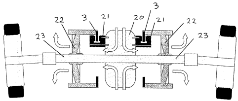
Fig. 4 shows a modified arrangement of a car in which
the braking system is mounted on rear axles 23 of a vehicle
away from the wheels. In the example shown the systems are
mounted on either side of a differential or gearbox unit 20
on which the brake callipers 21 for each of the systems are
mounted. Each braking system comprises a support
element 22 which is an open vaned element, which is mounted
on a respective axle 23 and which extends outwardly and is
connected at its periphery to a brake ring 3 on which the
callipers 21 act. The vaned support element 22 serves both
to generate an airflow in the region of the brake ring 3
and the callipers 21 and also, as a result of its fin-like
structure, cools the support element. Arrows show the
direction of airflow.
Fig. 5 shows an arrangement similar to that of Fig. 4
but applied to an axle of a railway vehicle having
wheels 25 on rails 26. The same reference numerals are
used In Fig. 5 as in Fig. 4 to designate corresponding
parts.
Fig. 6 shows schematically a braking system of the
kind shown in Figs. 4 and 5 with a fluid cooling system. A
sealed chamber 30 is provided in the region of the braking
system and refrigerant circulated along tubes 31 between
the chamber 30 and another heat exchanging radiator 32
where the refrigerant condenses and cools. It should be
understood that Fig. 6 is schematic and the chamber 30 may
for example only surround the calliper and be in sealing
contact with the brake ring 3.