Note: Descriptions are shown in the official language in which they were submitted.
CA 02642003 2009-04-23
DESCRIPTION
Structure Mounting an Electricity Storage Pack on a Vehicle
Technical Field
The present invention relates to structures mounting an electricity storage
pack
on a vehicle.
Background Art
In recent years an electric vehicle employing a motor as a driving source and
a
so called hybrid electric vehicle having a motor serving as a driving source
and another
driving source combined together are commercially available. Such vehicles
have
electricity storage equipment mounted therein for supplying the motor with
electricity
serving as energy. The electricity storage equipment is implemented for
example as a
secondary battery represented by a repeatedly rechargeable and dischargeable
nickel
cadmium battery, nickel hydrogen battery, lithium ion battery and the like, a
capacitor
and the like. The electricity storage equipment is accommodated in a case and
thus
mounted as an electricity storage pack on a vehicular body.
Japanese Patent Laying-Open No. 2001-113959 proposes a vehicular battery
mounting structure including a battery trestle bearing a battery box disposed
in a
vehicle at a rear portion on a floor for accommodating a battery, that is
formed of a
battery mounting portion supporting the battery box, a front leg and a rear
leg, with the
front leg and the rear leg formed to be fragile for the battery trestle. The
publication
discloses that when the vehicle is bumped at a rear portion and a load thus
acts thereon,
the vehicular battery mounting structure can have the fragile front and rear
legs
deformed to prevent the battery trestle from increasing the floor's rigidity
and thus
ensure the floor's crush stroke, and also prevent the battery mounting portion
from
deforming and thus protect the battery box, a battery and the like from
damage.
-1-
CA 02642003 2008-08-08
Japanese Patent Laying-Open No. 2005-247063 proposes an electricity storage
mechanism attaching structure attached to a side member positioned in a
vehicle at a
side. The side member has a kick up portion curved upward. A cross member is
provided at a front portion of the kick up portion to couple a pair of side
members
together at their respective side surfaces. A battery pack has a front portion
secured to
a top surface of the cross member by a front bracket welded to the front
portion of the
battery pack. The battery pack has a rear portion secured to a top surface of
the side
member at a rear portion of the kick up portion by a bridge provided to couple
the pair
of side members. The publication discloses that the electricity storage
mechanism
attaching structure can reduce or prevent damage to the electricity storage
mechanism
when the vehicle is bumped at the back.
Japanese Patent Laying-Open No. 6-270697 proposes an auxiliary component
arrangement structure for an electric vehicle. In an engine room over a motor,
there
are a plurality of auxiliary components such as an inverter, an auxiliary
battery, an
inverter for an air conditioner and the like arranged in the vehicle's body
from front to
back in order. These auxiliary components are each coupled to an adjacent
auxiliary
component with a link. The link has opposite ends having coupling points to
have
positions, respectively, straddling the vehicle's longitudinal axis vertically
opposite to
each other. The publication discloses that when the vehicle is bumped at the
front and
thus experiences a load compressively deforming its front body, the auxiliary
component
arrangement structure allows an auxiliary component posed between two other
auxiliary
components to move in a direction further diverting from the vehicle's
longitudinal axis
as the link acts, which can reduce an amount of collision load transmitted
rearward from
the vehicle's front portion through the auxiliary components, and hence
collision load
exerted from the vehicle's front portion and reaching the vehicle's cabin.
Japanese Patent Laying-Open No. 2004-243847 proposes a battery support
device. More specifically, when a physical impact is exerted from above a
battery, the
device disengages the battery and a side member fastened (or secured) together
and
-2-
CA 02642003 2008-08-08
rotationally displaces the battery downward to ensure deformability for the
vehicular
body when it receives physical impact (or ensure a space between a hood and
the battery
by rotationally displacing the battery).
An electricity storage pack is secured to a floor panel, a side member or a
similar
support member supporting the electricity storage pack. For example when
vehicles
collide with each other and the electricity storage pack directly receives
physical impact,
the electricity storage pack may receive physical impactive force and be
damaged, or
sudden braking or the like may cause a load on the vehicle to impinge on the
electricity
storage pack and thus exert physical impactive force to the electricity
storage pack.
Furthermore even if the electricity storage pack does not receive physical
impact
directly, being bumped by a vehicle from behind or the like may deform the
support
member, and as the supporting member is deformed, the electricity storage pack
per se
may receive a load. Furthermore, as the supporting member is deformed, the
electricity
storage pack may come off the support member, smash another portion and thus
experience physical impactive force.
In particular, if the electricity storage pack has damaged a case
accommodating a
storage battery or similar electricity storage equipment and the internal
electricity
storage equipment is exposed, the electricity storage equipment may receive
physical
impact or the like further directly and may not be protected appropriately.
Disclosure of the Invention
The present invention contemplates a structure mounting an electricity storage
pack on a vehicle, that can reduce or prevent damage to the electricity
storage pack
when the vehicular body or the electricity storage pack receives physical
impact.
The present invention in one aspect provides a structure mounting an
electricity
storage pack on a vehicle, that includes a support member formed to support
the
electricity storage pack, and a securing member securing the electricity
storage pack to
the support member. The securing member has one side pivotably coupled to the
-3-
CA 02642003 2008-08-08
electricity storage pack and the other side pivotably coupled to the support
member.
In the present invention preferably the electricity storage pack is disposed
in a
vehicular body at one of a rear portion and a front portion.
In the present invention preferably the securing member is formed to have a
longitudinal direction. The securing member has the longitudinal direction
substantially
parallel to a widthwise direction of a vehicular body.
In the present invention preferably the electricity storage pack has one of a
front
end and a rear end supported by the support member via the securing member.
The
electricity storage pack has the other end secured to the support member with
a screw.
The electricity storage pack has a screw hole formed to receive the screw. The
electricity storage pack has a thin portion surrounding the screw hole. The
thin portion
is formed to be thinner than a portion surrounding the thin portion.
In the present invention preferably the electricity storage pack has one of a
front
end and a rear end supported by the support member via the securing member.
The
electricity storage pack has the other end secured to the support member with
a screw.
The electricity storage pack has a screw hole formed to receive the screw. The
screw
hole is formed to extend in a longitudinal direction of a vehicular body.
Furthermore the present invention in another aspect provides a structure
mounting (or attaching) an electricity storage pack on a vehicle, the
electricity storage
pack being secured to a support member by an attachment portion provided at
each of
one and the other ends of the electricity storage pack accommodating
electricity storage
equipment. One attachment portion has a disengagement portion for disengaging
the
support member and the electricity storage pack secured together at the
attachment
portion, and the other attachment portion includes a first attachment portion
and a
second attachment portion distant from each other. When physical impact is
received
at one of the first attachment portion and the second attachment portion, the
electricity
storage pack is disengaged from the support member at one attachment portion
and
deforms as the electricity storage pack pivots around one of the first
attachment portion
-4-
CA 02642003 2008-08-08
and the second attachment portion opposite to that receiving the physical
impact.
Furthermore, the first attachment portion can include a slit portion allowing
the
electricity storage pack to move toward the second attachment portion when
physical
impact is received, and the second attachment portion can include a slit
portion allowing
the electricity storage pack to move toward the first attachment portion when
physical
impact is received.
Furthermore, the electricity storage pack is secured to the support member by
one and the other attachment portions with an attachment bolt, and the
disengagement
portion can have a disengagement hole larger than the head of the attachment
bolt.
Furthermore, one attachment portion has a slit portion allowing the
electricity
storage pack to move toward one of the first attachment portion and the second
attachment portion when physical impact is received, and the slit portion can
have an
end having the disengagement portion.
Furthermore preferably the slit portion of the first and second attachment
portions is larger in length than the slit portion of one attachment portion.
Furthermore, the slit portion has a lengthwise direction substantially
parallel to a
direction in which one of a vehicular body and the electricity storage pack
receives
physical impact, and furthermore, the first and second attachment portions may
have a
slit portion having a lengthwise direction oblique with respect to a direction
in which
one of a vehicular body and the electricity storage pack receives physical
impact.
Furthermore, the present invention in still another aspect provides a
structure
mounting (or attaching) an electricity storage pack on a vehicle, the
electricity storage
pack being secured to a support member and accommodating electricity storage
equipment therein. The support member includes an attachment portion for
securing
the electricity storage pack at one and the other ends to the support member.
One
attachment portion has a disengagement portion for disengaging the support
member
and the electricity storage pack secured together at the attachment portion,
and the
other attachment portion is configured of a first attachment portion and a
second
-5-
CA 02642003 2008-08-08
attachment portion distant from each other. When physical impact is received
at one of
the first attachment portion and the second attachment portion, the support
member is
disengaged from the electricity storage pack at one attachment portion to
allow the
electricity storage pack to pivot around one of the first attachment portion
and the
second attachment portion opposite to that receiving the physical impact and
thus
deform.
Brief Description of the Drawings
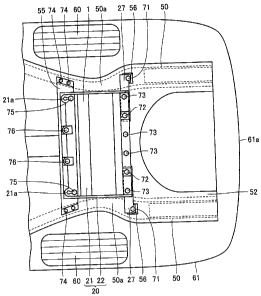
Fig. I is a first schematic cross section of the portion of a battery pack in
a first
embodiment of the present invention.
Fig. 2 is a schematic perspective view of the battery pack and a securing
member
in the first embodiment of the present invention.
Fig. 3 is a schematic, exploded perspective view of the battery pack and the
securing member in the first embodiment of the present invention.
Fig. 4 is a schematic plan view of the battery pack and the securing member in
the first embodiment of the present invention.
Fig. 5 is a second schematic cross section of the portion of the battery pack
in
the first embodiment of the present invention.
Fig. 6 is an exploded, schematic perspective view of a support member for
supporting the battery pack in the first embodiment of the present invention.
Fig. 7 is a first schematic cross section of the portion of the battery pack
in the
first embodiment when physical impact is experienced in the vehicular body's
longitudinal direction.
Fig. 8 is a second schematic cross section of the portion of the battery pack
in
the first embodiment when physical impact is experienced in the vehicular
body's
longitudinal direction.
Fig. 9 is an enlarged schematic plan view of another screw hole receiving a
screw securing the electricity storage pack to the support member in the first
-6-
CA 02642003 2008-08-08
embodiment.
Fig. 10 is a schematic cross section of the portion of a battery pack in a
second
embodiment of the present invention.
Fig. 11 is a schematic cross section of a battery pack mounted in a vehicular
body in a third embodiment of the present invention.
Fig. 12 is a schematic perspective view of the battery pack in the third
embodiment of the present invention.
Fig. 13A and Fig. 13B are schematic views for illustrating the battery pack
rotationally deforming when it receives physical impact in the third
embodiment.
Fig. 14A and Fig. 14B are schematic views for illustrating the battery pack in
the
third embodiment rotationally deforming when it receives physical impact.
Fig. 15 is a schematic cross section of a battery pack mounted in a vehicular
body in a fourth embodiment of the present invention.
Fig. 16 is a schematic cross section of the battery pack mounted in the
vehicular
body in the fourth embodiment of the present invention.
Fig. 17 is a schematic perspective view of the battery pack in the fourth
embodiment of the present invention.
Fig. 18A and Fig. 18B are schematic views for illustrating the battery pack in
the
fourth embodiment rotationally deforming when it receives physical impact.
Best Modes for Carrying Out the Invention
First Embodiment
Reference will now be made to Fig. 1 to Fig. 9 to describe a structure
mounting
an electricity storage pack on a vehicle in a first embodiment of the present
invention.
A secondary battery, a capacitor or similar electricity storage equipment is
accommodated in a case and thus mounted in a vehicle. In the present
invention,
equipment including the case and the electricity storage equipment
accommodated in the
case will be referred to as an electricity storage pack. The electricity
storage pack may
-7-
CA 02642003 2008-08-08
include other internal components including such as a cooling device such as a
cooling
duct, a cooling fan and the like for cooling the electricity storage
equipment, electronics
converting power, and the like.
Fig. 1 is a schematic cross section of the portion of the battery pack in the
present embodiment. Fig. 1 shows a rear portion of a vehicular body. In the
present
invention a so-called sedan vehicle will be described. The vehicle includes a
body 61.
Body 61 is formed to be generally a quadrangle when it is seen in a plane.
Body 61 has
a rear surface 61a. The vehicular body has a rear portion having a rear wheel
60.
In the present embodiment the electricity storage pack implemented as a
battery
pack 1 is disposed in the vehicular body at a rear portion. Battery pack 1 is
disposed in
a trunk room. Battery pack 1 includes a case implemented as a battery case 20.
Battery case 20 internally accommodates electricity storage equipment
implemented as a
storage battery. While the present embodiment provides battery case 20 formed
of iron,
the electricity storage equipment's case may be formed of any material.
In the present embodiment the vehicle includes a support member formed to
support battery pack 1. The support member includes a side member (or side
frame)
50. Side member 50 configures a portion of the main body of the vehicular
body.
Side member 50 is disposed in the vehicular body at opposite sides as seen in
the
vehicular body's widthwise direction. Side member 50 extends in the vehicular
body's
longitudinal direction.
Battery pack 1 has a front end supported by side member 50 via a mount 55 and
a floor member 52. Battery pack 1 has a rear end supported by side member 50
via a
rear bracket 27, a mount 56 and floor member 52.
Side member 50 has an upper surface with floor member 52 disposed thereon.
Floor member 52 is formed in the form of a plate. Floor member 52 is disposed
to
straddle a portion between side members 50 disposed in the vehicular body at
the
opposite sides as seen in the vehicular body's widthwise direction. Mounts 55,
56 are
disposed on a surface of floor member 52.
-8-
CA 02642003 2008-08-08
In the present embodiment the vehicle includes rear bracket 27 as a securing
member for securing battery pack 1 to side member 50. Rear bracket 27 is
coupled to
mount 56 with a screw implemented as a bolt 71. Mount 56 is secured to side
member
50. Rear bracket 27 is coupled to battery pack I with a bolt 72. In the
present
embodiment rear bracket 27 is formed of iron.
In the present embodiment rear bracket 27 is formed to have a longitudinal
direction. Rear bracket 27 is formed in the form of a plate. Rear bracket 27
is
coupled to battery pack 1 at a rear end at opposite sides as seen in the
widthwise
direction. Rear bracket 27 is coupled to have its longitudinal direction
substantially
parallel to the vehicular body's widthwise direction.
Battery pack 1 has a front end connected to mount 55 with a bolt 75. Mount
55 extends in the vehicular body's widthwise direction. Mount 55 is formed to
bridge
two side members 50. Mount 55 is secured to side member 50 with a bolt 74.
Fig. 2 is a schematic perspective view of the battery pack and the rear
bracket in
the present embodiment. Fig. 3 shows an exploded perspective view of the
battery
pack and the rear bracket in the present embodiment. The battery pack 1
battery case
is in the form of a box. Battery case 20 includes an upper case 21 and a lower
case
22. Rear bracket 27 has an outer end with a screw hole 27a. Rear bracket 27
has an
inner end with a screw hole 27b.
20 Lower case 22 has an upper surface, on which electricity storage equipment
implemented as a storage battery 25 is disposed. In the present embodiment,
storage
battery 25 includes a plurality of battery cells 25a. Battery cells 25a are
stacked in
layers. Upper case 21 covers storage battery 25.
With reference to Fig. 1 to Fig. 3, upper case 21 has a front end with screw
holes
21a, 21b. Lower case 22 has a front end with screw holes 22a, 22b. Screw hole
2la
and screw hole 22a have their respective positions to correspond to each
other. Screw
hole 21b and screw hole 22b have their respective positions to correspond to
each other.
Screw holes 21b, 22b receive screws implemented as a bolt 76 to fasten upper
case 21
-9-
CA 02642003 2008-08-08
and lower case 22 together. Furthermore, screw holes 21 a, 22a receive a bolt
75 to
couple battery pack 1 to mount 55.
Lower case 22 has a rear end with screw holes 22c, 22d. Upper case 21 has a
rear end having screw holes formed to correspond to screw holes 22c, 22d.
Screw
hole 22c and a screw hole of upper case 21 that corresponds thereto receive a
bolt 73 to
fasten upper case 21 and lower case 22 together. Furthermore, screw hole 22d,
a
screw hole of upper case 21 that corresponds thereto, and the rear bracket 27
screw
hole 27b receives bolt 72 to fasten upper case 21 and lower case 22 together
and also
couple rear bracket 27 to battery case 20.
Fig. 4 is a schematic plan view of the battery pack and the rear bracket in
the
present embodiment. An arrow 89 indicates the vehicular body's front side.
Upper
case 21 and lower case 22 are fastened to each other with bolts 73, 76. Rear
bracket
27 is coupled to battery pack 1 with bolt 72. Rear bracket 27 is coupled
pivotably
around bolt 72 serving as an axis of pivotation, as indicated by arrow 85.
Furthermore, in the present embodiment, with reference to Fig. 1, rear bracket
27 has an outer side coupled to side member 50 pivotably. Rear bracket 27 is
connected to mount 56 pivotably around bolt 71 serving as an axis of
pivotation. Thus
in the present embodiment rear bracket 27 has one side coupled to battery pack
1
pivotably and the other side coupled to side member 50 pivotably.
With reference to Fig. 3 and Fig. 4, at a front end of battery pack 1 at
opposite
sides as seen in the widthwise direction, upper case 21 has screw hole 21 a
and lower
case 22 has screw hole 22a. Screw holes 21 a, 22a have a longitudinal
direction.
Screw holes 21a, 22a extend in the vehicular body's longitudinal direction.
Screw hole
21 a formed in upper case 21 and screw hole 22a formed in lower case 22 are
substantially identical in geometry.
In the present embodiment screw holes 21a, 22a have a front round portion 33a
and a rear round portion 33c communicating through a communication portion
33b.
Front round portion 33a and rear round portion 33c are formed to have a
diameter
-10-
CA 02642003 2008-08-08
larger than a bolt's shank. Communication portion 33b is formed to have a
width
smaller than the bolt's shank. Before physical impact is received, screw 75 is
located in
rear round portion 33c (see Fig. 1).
Fig. 5 is a second schematic cross section of a structure mounting a battery
pack
on a vehicle in the present embodiment. Fig. 5 is a schematic cross section
provided
when the vehicular body is cut along a plane extending in a vertical
direction. Behind a
rear seat 62 a partition panel 63 is disposed. Partition panel 63 partitions
the cabin and
the trunk room. In the present embodiment battery pack 1 is disposed in the
trunk
room.
Side member 50 has a kick up portion 50a formed to swell upward. Battery
pack 1 is disposed at kick up portion 50a. Mounts 55, 56 are spaced by a
distance
indicated by an arrow 88a. Arrow 88a indicates a length extending along an
upper
surface of side member 50. Battery pack I is supported to be substantially
horizontal
when it is seen sideways.
Fig. 6 is a schematic, exploded perspective view of the support member in the
present embodiment. In the present embodiment the support member includes side
member 50, a cross member 51 and floor member 52. Cross member 51 secures side
members 50 together. Floor member 52 is disposed on an upper surface of side
member 50 and that of cross member 51.
In the present embodiment the support member includes mounts 55, 56.
Mounts 55, 56 are secured to a surface of floor member 52. In the present
embodiment, side member 50 is welded and thus secured to cross member 51.
Floor
member 52 is welded and thus secured to side member 50. Mounts 55, 56 are
welded
and thus secured to floor member 52.
Fig. 7 is a first schematic cross section of the vehicle of the present
embodiment
receiving a longitudinal physical impact. Fig. 7 is a view corresponding to
Fig. 5. For
example, if the longitudinal physical impact is received by the vehicular body
at a rear
portion as it is bumped by another vehicular body from behind, then, as
indicated by an
-11-
CA 02642003 2008-08-08
arrow 86, the vehicular body longitudinally receives a load. The side member
50 kick
up portion 50a, curved upward, is further curved, as indicated by an arrow 87.
At the
time, a distance between mount 55 and mount 56, as indicated by an arrow 88b,
is
increased to be larger than that before the vehicle is bumped from behind. In
the
present embodiment battery case 20 deforms at the time.
Fig. 8 is a second schematic cross section of the vehicle of the present
embodiment receiving a longitudinal physical impact. For example when the
vehicle is
bumped at the back, rear bracket 27 disposed behind battery pack 1 pivots.
Rear
bracket 27 has its lengthwise direction diverted from a position substantially
parallel to
the vehicular body's widthwise direction. Bolt 72 supporting rear bracket 27
positionally shifts relatively more forward than bolt 71 supporting rear
bracket 27.
At the front side of battery pack 1, bolt 75 moves in screw hole 21 a to front
round portion 33a. More specifically, the bolt 75 shank moves from rear round
portion
33c to front round portion 33a. In doing so, bolt 75 spreads communication
portion
33b connecting front and rear round portions 33a, 33c together.
Thus the present embodiment provides a structure mounting an electricity
storage pack on a vehicle, that allows the electricity storage pack to be
supported in a
manner varying to reduce damage to the electricity storage pack. In
particular, the
structure can prevent the electricity storage pack from coming off a support
member.
While the above describes that a support member supporting an electricity
storage pack is deformed by way of example, a similar effect can also be
obtained when
the electricity storage pack directly receives physical impact. For example,
if the
electricity storage pack is disposed in the trunk room, and the vehicle for
example
bumps into a preceding vehicle and a load placed in the trunk room collides
directly
against the electricity storage pack, the securing member can pivot to reduce
damage to
the electricity storage pack.
In the present embodiment the electricity storage pack is disposed in a
vehicular
body at a rear portion. This configuration can effectively reduce or prevent
damage to
-12-
CA 02642003 2008-08-08
the electricity storage pack when the vehicular body receives physical impact
from
behind. The vehicular body would receive physical impact mainly when it has
collision
at the front or the back. As well as vehicles bumping into each other,
erroneous
driving operation or the like would also cause the vehicle to crash into a
building.
Depositing the electricity storage pack in a vehicle at a front or rear
portion that is an
end portion as seen in a direction in which the vehicle travels renders the
present
invention's effect remarkable. If the electricity storage pack is disposed in
the vehicular
body at the front portion, the electricity storage pack is disposed for
example in the
engine room.
The present embodiment provides a securing member implemented as a bracket
having a longitudinal direction substantially parallel to the vehicular body's
widthwise
direction. This configuration allows the securing member to efficiently pivot
when the
vehicular body receives longitudinal physical impact.
Furthermore in the present embodiment the battery pack has one end secured to
a mount with a screw inserted into screw hole 21 a (see Fig. 4) extending in
the vehicle's
longitudinal direction. Thus, when the electricity storage pack receives a
load, the
electricity storage pack can have one end moved relative to the screw to
accommodate
the support member's deformation.
While the electricity storage pack has a front end with a screw hole in the
form
of an elongate hole having a longitudinal direction, the screw hole is not
limited thereto,
and may for example be a round screw hole as seen in a plane. Furthermore, as
will be
described later, the screw hole may be surrounded by a thin portion.
While in the present embodiment a pivotably coupled securing member is
coupled to an electricity storage pack at a rear side thereof, it is not
limited thereto and
may be disposed at any side. For example, if it is assumed that a load is
exerted in a
lateral direction of the vehicular body, the securing member may be disposed
in the
lateral direction of the vehicular body.
Fig. 9 is an enlarged schematic plan view of a screw hole of another
electricity
- 13 -
CA 02642003 2008-08-08
storage pack in the present embodiment. This electricity storage pack has an
upper
case 31. Upper case 31 has a screw hole 31 a. Screw hole 31 a is a portion
corresponding in the Fig. 4 upper case 21 to screw hole 21 a. Screw hole 31 a
is formed
to be substantially round as seen in a plane.
Screw hole 3la is surrounded by a thin portion 3 lb. Thin portion 3lb is
formed to be smaller in thickness than a portion outer than and surrounding
thin portion
31b. Thin portion 3lb has a longitudinal direction. Thin portion 3 lb extends
in the
vehicular body's longitudinal direction. Thin portion 3lb is provided
forwardly of
screw hole 31 a. A lower case is also similarly configured. More specifically,
the
upper and lower cases have their respective screw holes surrounded by thin
portions,
respectively.
A screw hole receiving a screw securing the electricity storage pack to the
support member that is surrounded by a thin portion allows the screw's shank
in the
screw hole to move when the vehicular body receives physical impact. This
tears thin
portion 3lb and thus allows the electricity storage pack to follow the support
member's
deformation. Alternatively the physical impact's energy can be absorbed as the
screw's
shank travels thin portion 3 lb.
While in the present embodiment the electricity storage pack has a case formed
to be deformable, it is not limited thereto. In addition to the case, the
securing member
implemented as a bracket may also be formed to be deformable. The securing
member
can be formed of any material.
Second Embodiment
With reference to Fig. 10, the present invention in a second embodiment
provides a structure mounting an electricity storage pack on a vehicle, as
will be
described hereinafter. The present embodiment provides a structure mounting an
electricity storage pack on a vehicle, that supports the electricity storage
pack's front
portion by a structure different from that described in the first embodiment.
Fig. 10 is a schematic cross section of a structure mounting a battery pack on
a
- 14-
CA 02642003 2008-08-08
vehicle in the present embodiment. In the present embodiment the structure
mounting
a battery pack on a vehicle employs four securing members to secure a battery
pack to a
support member.
The structure mounting a battery pack on a vehicle includes a securing member
implemented as a front bracket 45 disposed at a front end of a battery pack 2.
Battery
pack 2 includes an upper case 41 and a lower case 42. Upper case 41 and lower
case
42 are fastened together by bolts 73, 77.
Front bracket 45 is pivotably coupled to lower case 42 with a bolt 79. Front
bracket 45 is pivotably coupled to a mount 46 with a bolt 78. Mount 46 is each
disposed at opposite sides as seen in the widthwise direction, and secured to
side
member 50.
Thus a pivotable securing member can be disposed at an end, as seen in a
direction in which it is assumed that the vehicular body receives physical
impact, to
alone support the electricity storage pack to also reduce or prevent damage to
the
electricity storage pack against large physical impact. For example it can
ensure less or
no damage to the electricity storage pack for example when the support member
significantly deforms.
The remainder in configuration, and function and effect is similar to that of
the
structure mounting an electricity storage pack on a vehicle in the first
embodiment.
Accordingly it will not be described repeatedly. Furthermore, in the above
described
figures, identical or corresponding components are identically denoted.
Third Embodiment
With reference to Fig. 11 to Fig. 14B, the present invention in a third
embodiment provides a structure mounting (or attaching) an electricity storage
pack to a
vehicle, as will be described hereinafter.
With reference to Fig. 11, the present embodiment provides a structure
mounting
an electricity storage pack on a vehicle, that has an electricity storage pack
implemented
as a battery pack 3 having an end closer to the front side of the vehicular
body that is
- 15 -
CA 02642003 2008-08-08
supported by side member 50 via mount 55 and floor member 52, and an end
closer to
the rear side of the vehicular body that is supported by side member 50 via a
mount 56a
and floor member 52, rather than rear bracket 27 described in the first
embodiment.
The remainder in configuration similar to that of the first embodiment will be
identically
labeled and will not be described repeatedly.
The present embodiment provides battery pack 3 including an upper case 301
and a lower case 302. Similarly as has been described in the first embodiment,
on an
upper surface of lower case 302 is disposed electricity storage equipment
implemented
as a storage battery 25 including a plurality of battery cells 25a stacked in
layers, and
upper case 301 covers storage battery 25. Upper case 301 and lower case 302
each
have ends closer to the front and rear sides, respectively, of the vehicular
body that have
attachment portions A, B (B 1, B2, B3) receiving bolts 76a and 72a to secure
battery
pack 3 to the support member implemented as mount 55 and mount 56a.
Furthermore,
upper case 301 and lower case 302 are also fastened together. Upper case 301
and
lower case 302 are configured of aluminum metal or a similar material.
As shown in Fig. 12, attachment portion A includes an attachment hole T2
receiving the shank of bolt 76a, slits S3 and S4 extending in battery pack 3
in a
widthwise direction of the vehicular body, and a disengagement hole H having a
diameter larger than the head of bolt 76a. Slits S3, S4 are elongate holes
adjacent to
attachment hole T2 receiving bolt 76a, such that they are opposite to each
other in the
widthwise direction of the vehicular body to sandwich attachment hole T2, and
couple
attachment hole T2 and disengagement hole H together. Furthermore, in the
present
embodiment, attachment portion A is provided in the end portion of battery
pack 3
closer to the front side of the vehicular body, at three attachment positions,
and slits S3,
S4 are equal in length.
Attachment portion B is provided in the end portion of battery pack 3 closer
to
the rear side of the vehicular body at three attachment positions and includes
an
attachment hole Ti receiving the shank of bolt 72a and a slit Si or/and S2
extending in
-16-
CA 02642003 2008-08-08
battery pack 3 in the widthwise direction of the vehicular body. As shown in
Fig. 11
and Fig. 12, of three attachment portions B, an attachment portion B 1 (or a
first
attachment portion) includes a slit S 1 coupled to attachment hole Ti and
extending
rightward (in Fig. 11, upward) in the widthwise direction of the vehicular
body. An
attachment portion B2 (a second attachment portion) includes a slit S2 that
couples to
attachment hole TI distant from attachment portion B 1 and extends leftward
(in Fig. 11,
downward) in the widthwise direction of the vehicular body and hence in a
direction
opposite to that in which slit Si extends. An attachment portion B3 is located
between
attachment portion B 1 and attachment portion B3 and includes slit S 1 and
slit S2
adjacent to attachment hole Ti opposite as seen in the widthwise direction of
the
vehicular body.
Thus attachment portion B I has slit S 1 formed to be an elongate hole that
allows
battery pack 3 receiving physical impact at a side closer to attachment
portion B 1 to
displace (or deform) toward attachment portion B2 and does not allow battery
pack 3
receiving physical impact at a side closer to attachment portion B2 to
displace toward
attachment portion B 1, and attachment portion B2 also has slit S2 formed to
be an
elongate hole that allows battery pack 3 receiving physical impact at a side
closer to
attachment portion B2 to displace toward attachment portion B I and does not
allow
battery pack 3 receiving physical impact at a side closer to attachment
portion B 1 to
displace toward attachment portion B2.
Furthermore the elongate holes of slits Si and S2 of attachment portion B are
larger in length than those of slits S3 and S4 of attachment portion A, as
seen in their
lengthwise direction, and slits S I -S4 have their lengthwise direction
substantially parallel
to a direction in which the vehicular body or battery pack 3 receives physical
impact.
In the present embodiment battery pack 3 is secured to a support member at
attachment portions A, B having attachment portion A provided with
disengagement
hole H having a diameter larger than the head of bolt 76a for disengaging the
support
member and battery pack 3 secured together at attachment portion A, and
attachment
-17-
CA 02642003 2008-08-08
portion B including first attachment portion B 1 and second attachment portion
B2
distant from each other. When physical impact is received at a side closer to
first
attachment portion B 1 or that closer to second attachment portion B2, battery
pack 3
can be disengaged from the support member at attachment portion A, and battery
pack 3
as described above, i.e., battery pack 3 accommodating an electricity storage
device
implemented as storage battery 25, can have upper case 301 and lower case 302
deformed such that the cases pivot around first attachment portion B 1 or
second
attachment portion B2 that is opposite to that receiving the physical impact
(and that
end of battery pack 3 which has attachment portion A acts as a free end). Thus
the
physical impact can be absorbed and dispersed and battery pack 3 can suitably
be
protected.
Furthermore, as shown in Fig. 11, while the present embodiment assumes that a
vehicular body receives physical impact laterally or in a widthwise direction
of the
vehicular body relative to a longitudinal direction of the vehicular body,
i.e., that a
vehicle is bumped sideways, and battery pack 3 thus receives a load of
physical
impactive force, the structure mounting an electricity storage pack on a
vehicle in the
present embodiment is applicable to physical impact or collision acting on
battery pack 3
in a direction substantially parallel to that in which the elongate holes of
the slits of
attachment portions A and B have their respective lengthwise directions, and
it is also
applicable to a load of physical impactive force exerted on battery pack 3 in
the
longitudinal direction of the vehicular body if attachment portions A, B and
their slits'
lengthwise directions are modified to accommodate the physical impact exerted
in the
longitudinal direction of the vehicular body.
Reference will now be made to Fig. 13A and Fig. 13B to describe how battery
pack 3 of the present embodiment behaves when it receives physical impact. An
arrow
501 indicates a direction in which the physical impact is exerted. An arrow
502
indicates how battery pack 3 deforms. An arrow 503 indicates how battery pack
3
slides. An arrow 504 indicates how battery pack 3 slidingly and compressively
deforms.
-18-
CA 02642003 2008-08-08
If in the Fig. 13A condition the vehicular body or battery pack 3 receives
physical impact in the widthwise direction of the vehicular body at a side
closer to
attachment portion B2, then, as shown in Fig. 13B, battery pack 3 elastically
and
plastically deforms and thus displaces (or deforms) in a direction in which
the physical
impactive force acts. As battery pack 3 displaces, the shank of attachment
bolt 76a in
attachment portion A passes through slit S4 and thus reaches disengagement
hole H.
This causes a physical impact causing the head of attachment bolt 76a to come
off
disengagement hole H, and mount 55 and battery pack 3 at attachment portion A
are
disengaged (or the force of bolt 76a fastening mount 55 and battery pack 3
together is
released).
At attachment portion B, on the other hand, while battery pack 3 as a whole
displaces rightward (in the figure, upward), the attachment portion B 1 slit
Si does not
allow the physical impact received from the side closer to attachment portion
B2 to
displace battery pack 3 rightward (in the figure, upward) and the attachment
portions B2
and B3 slits S2 allow the physical impact received from the side closer to
attachment
portion B2 to displace battery pack 3 rightward (in the figure, upward), as
has been
described above, and upper case 301 and lower case 302 (compressively) deform
in a
vicinity of attachment portion B2 and attachment portion B3 to allow battery
pack 3 to
displace rightward (in the figure, upward).
Thus, as shown in Fig. 13B, when battery pack 3 receives physical impact at
the
side closer to second attachment portion B2, attachment portion A comes off
mount 55
and attachment portion B 1 prevents battery pack 3 from moving toward
attachment
portion B 1. Battery pack 3 pivots around bolt 72a of attachment portion B l,
while
battery pack 3 deforms, and thus absorbs and disperses the physical impact. As
attachment portion B 1 prevents battery pack 3 from moving toward attachment
portion
B l, battery pack 3 does not entirely displace toward attachment portion B l.
Rather,
battery pack 3 deforms such that it pivots around bolt 72a of attachment
portion B 1,
and upper case 301 and lower case 302 compressively deform (or compressively
-19-
CA 02642003 2008-08-08
displace) in a vicinity of attachment portion B2 and attachment portion B3.
In the present embodiment when the vehicular body or battery pack 3 receives
physical impact at attachment portion B2 the structure mounting an electricity
storage
pack on a vehicle allows battery pack 3 to displace as it deforms gradually
such that it
pivots around bolt 72a of attachment portion B1, i.e., an attachment portion
opposite to
attachment portion B2 receiving the physical impact. This can appropriately
absorb
and disperse energy with respect to physical impact and hence prevent physical
impact
from excessively deforming battery pack 3. Note that when physical impact
deforms
battery pack 3, the second attachment portion implemented as attachment
portion B2
may come off the support member. More specifically, when the second attachment
portion implemented as attachment portion B2 comes off the support member,
battery
pack 3 having plastically deformed has sufficiently absorbed physical impact.
Accordingly, attachment portion B2 may be configured to come off the support
member
before upper case 301 and lower case 302 rapture as they plastically deform.
Furthermore, the attachment portion B slits Si and S2 each have an elongate
hole having in its lengthwise direction a length larger than the attachment
portion A slits
S3 and S4 each do. This ensures that battery pack 3 receiving physical impact
and thus
displacing displaces slidingly in a direction in which the physical impact
acts, until the
shank of attachment bolt 76a in attachment portion A passes through slit S3 or
S4 and
reaches disengagement hole H and thus causes physical impact causing the head
of
attachment bolt 76a to come off disengagement hole H, so that the head of bolt
76a can
readily come off disengagement hole H. Note that slits S3 and S4 may each have
an
elongate hole having a width larger at portions closer to disengagement hole H
than
those closer to attachment hole T2 so that the slits can have a width
increasing from
attachment hole T2 toward disengagement hole H.
Furthermore while Fig. 11 to Fig. 13B show slits S1-S4 having a lengthwise
direction substantially parallel to a direction in which the vehicular body or
battery pack
3 receives physical impact, attachment portion B1 and attachment portion B3
may have
-20-
CA 02642003 2008-08-08
slits Si and S2 having a lengthwise direction oblique relative to the
direction in which
the vehicular body or battery pack 3 receives physical impact, as shown in
Fig. 14A and
Fig. 14B as slits S I a, S2a. The slits may have a linear geometry or a curved
geometry
having a curvature.
More specifically, to allow battery pack 3 to displace while gently deforming
such that it pivots around bolt 72a of attachment portion B 1, i.e., an
attachment portion
that is opposite to attachment portion B2 receiving physical impact when the
vehicular
body or battery pack 3 receives the physical impact at attachment portion B2,
slit S 1 a or
S2a may have a lengthwise direction that is perpendicular to a direction in
which the
vehicular body or battery pack 3 receives the physical impact and that
inclines toward
attachment portion A to increase the displaceability of battery pack 3
receiving the
physical impact (i.e., the displaceability of battery pack 3 at attachment
portion B2 in the
vehicular body's longitudinal direction) and reduce the deformability of
battery pack 3,
and also achieve more appropriate absorption and dispersion of energy with
respect to
physical impact.
Note that when battery pack 3 is allowed to displace in a direction
perpendicular
to that in which the vehicular body or battery pack 3 receives physical
impact, more
appropriate absorption and dispersion of energy with respect to the physical
impact can
be achieved. Accordingly, slits S 1 and S2 may be formed for example in the
letter of T
or a cross.
Alternatively, attachment portion A may be configured to dispense with slits
S2
and S3 and have disengagement hole H and attachment hole T2 adjacently.
Alternatively, attachment portions A, B may dispense with attachment holes Ti,
T2
receiving the shanks of bolts 76a and 72a and instead have their slits'
elongate holes to
also serve as attachment holes Ti, T2 to receive the shanks of bolts 76a and
72a.
Furthermore, one of upper case 301 and lower case 302 may have attachment
holes A and B and the other of the cases that has no attachment hole may be
configured
to be secured to that having the attachment holes, and the support member and
one of
-21-
CA 02642003 2008-08-08
the cases may be secured together.
Furthermore while in the present embodiment battery pack 3 has ends each
having attachment portions at three attachment positions, battery pack 3 may
have ends
each having attachment portions at at least two positions in view of ensuring
that battery
pack 3 and the support member are firmly secured together.
Fourth Embodiment
With reference to Fig. 15 to Fig. 18B, the present invention in a fourth
embodiment provides a structure mounting (or attaching) an electricity storage
pack on
a vehicle, as will be described hereinafter.
As shown in Fig. 15 and Fig. 16, the present embodiment provides an
electricity
storage pack implemented as a battery pack 4 disposed in a vehicular body
under a rear
seat and having an end closer to a front side of the vehicular body that is
supported by
side member 50 via a mount 55a and floor member 52, and an end closer to a
rear side
of the vehicular body that is supported by side member 50 via a mount 56a and
floor
member 52. The remainder in configuration similar to that described in the
first or
third embodiment will be denoted identically and will not be described.
In the present embodiment battery pack 4 includes an upper case 401 and a
lower case 402, and, as shown in Fig. 17 to Fig. 18B, a plurality of storage
batteries 25
implemented as a battery module BM are disposed at predetermined intervals,
with a
control unit (a monitoring unit) CU posed therebetween. Upper case 401 is
formed to
be lower at a portion covering control unit CU than that covering battery
module BM,
and thus has a recess between battery modules BMs.
Typically under a seat a slide mechanism (or a rail R) is provided to allow
the
seat to slide. In the present embodiment battery pack 4 allows rail R
projecting from
the seat downward to be disposed in the recess (or a rail passing portion 404)
that is
provided between battery modules BMs and hence in an efficiently utilized
space.
Battery pack 4 including upper case 401 and lower case 402 thus formed, as
well
as that in the third embodiment, has upper case 401 and lower case 402 such
that their
-22-
CA 02642003 2008-08-08
respective ends closer to the front side of the vehicular body and their
respective ends
closer to the rear side of the vehicular body have attachment portions A and B
(B 1, B2,
B3) receiving bolt 76a and bolt 72a, respectively. Bolt 76a and bolt 72a
secure battery
pack 4 to a support member implemented as mount 55a and mount 56a and also
fasten
upper case 401 and lower case 402 together. Furthermore, upper case 401 and
lower
case 402 are formed of aluminum metal or a similar material. Furthermore,
lower case
402 is provided with an air flow guiding portion 403 for introducing air
having flown
through battery pack 4, and discharging the air outside battery pack 4.
With reference to Fig. 18A and Fig. I8B, in the present embodiment when
battery pack 4 receives physical impact, battery pack 4 behaves, as will be
described
hereinafter. An arrow 501 indicates a direction in which the physical impact
is exerted.
An arrow 502 indicates how battery pack 3 deforms. An arrow 503 indicates how
battery pack 3 slides. An arrow 505 indicates how battery pack 3 slidingly and
compressively deforms.
If in the Fig. 18A condition the vehicular body or battery pack 4 receives
physical impact in the widthwise direction of the vehicular body at a side
closer to
attachment portion B2, then, as shown in Fig. 18B, battery pack 4 elastically
and
plastically deforms and thus displaces in a direction in which the physical
impactive force
acts. As battery pack 4 displaces, the shank of attachment bolt 76a in
attachment
portion A passes through slit S4 and thus reaches disengagement hole H. This
causes a
physical impact causing the head of attachment bolt 76a to come off
disengagement hole
H, and mount 55 and battery pack 3 at attachment portion A are disengaged (or
released) from each other.
At attachment portion B, on the other hand, while battery pack 4 displaces
rightward (in the figure, upward), the attachment portion B I slit S 1 does
not allow the
physical impact received from the side closer to attachment portion B2 to
displace
battery pack 4 rightward (in the figure, upward) and the attachment portions
B2 and B3
slits S2 allow the physical impact received from the side closer to attachment
portion B2
- 23 -
CA 02642003 2008-08-08
to displace battery pack 4 rightward (in the figure, upward), as has been
described above,
and upper case 401 and lower case 402 (compressively) deform in a vicinity of
attachment portion B2 and attachment portion B3 to allow battery pack 4 to
(compressively) displace rightward (in the figure, upward).
Thus, similarly as described in the third embodiment, battery pack 4 deforms
while pivoting around bolt 72a of attachment portion B 1 disallowing battery
pack 4 to
displace rightward (in the figure, upward) and thus absorbs and disperses
physical
impact, and in the present embodiment, upper case 401 and lower case 402
related to
rail passing portion 404 located between battery modules BMs (compressively)
deform
to be sandwiched between battery modules BMs, and thus absorb physical impact.
This can reduce in comparison with the third embodiment the displaceability of
battery pack 4 pivoting around bolt 72a of attachment portion B 1 opposite to
attachment portion B2 receiving physical impact when the vehicular body or
battery
pack 4 receives the physical impact at attachment portion B2, and it also
allows
sufficient absorption and dispersion of energy with respect to the physical
impact. This
can prevent battery pack 4 from excessively deforming, and also prevent
battery pack 4
from colliding against other members, components or the vehicular body when
battery
pack 4 deforms.
The third and fourth embodiments have been described with an electricity
storage pack provided with attachment portions A, B by way of example.
Alternatively,
for example, attachment portions A, B may be provided to mount 55a (55b) and
mount
56a (56b). In that case, the electricity storage pack is configured of upper
and lower
cases that do not have a disengagement hole or a slit. This can reduce the
cost for
producing the cases and prevent an attachment portion from having reduced
strength.
Furthermore in the third and fourth embodiments the support member and the
electricity storage pack are bolted together. Alternatively, for example, they
may be
fitted or engaged together by a recess and a projection, a protrusion, a hook,
or the like,
and thus secured together.
-24-
CA 02642003 2008-08-08
The present invention can thus provide a structure mounting an electricity
storage pack on a vehicle that can reduce or prevent damage to the electricity
storage
pack when the vehicular body or the electricity storage pack receives physical
impact.
It should be understood that the embodiments disclosed herein are illustrative
and non-restrictive in any respect. The scope of the present invention is
defined by the
terms of the claims, rather than the description above, and is intended to
include any
modifications within the scope and meaning equivalent to the terms of the
claims.
Industrial Applicability
The present invention is advantageously applicable to electricity storage
packs
mounted on automobiles.
-25-