Note: Descriptions are shown in the official language in which they were submitted.
CA 02642012 2008-08-08
1
DESCRIPTION
SHEET HEATING ELEMENT AND SEAT MAKING USE OF THE SAME
TECHNICAL FIELD
The present invention relates to a thin sheet heating element which is
flexible enough to be mounted in a sheet-form apparatus, having excellent
reliability and PTC characteristics. Also, the present invention relates to a
seat using the sheet heating element.
BACKGROUND ART
Conventional sheet heating elements are disclosed in Unexamined
Japanese Patent Publication 556-13689, Unexamined Japanese Patent
Publication H8-120182, and US Registered Patent No. 7,049,559. For the
heater section of a sheet heating element of this kind, a resistor made by
printing and drying resistor ink, with base polymer and conductive material
dispersed in a solvent, on a substrate is used. The resistor generates heat
with power supplied. Generally, for a resistor of this kind, carbon black,
metal
powder or graphite is used as the conductive material, while crystalline resin
is
used as the base polymer. Due to such materials, the heater section displays
PTC characteristics.
Fig. 21 is a perspective plan view of a conventional sheet heating
element. Fig. 22 is a sectional view across the line 22 - 22 of Fig. 21. As
shown in Fig. 21 and Fig. 22, sheet heating element 60 includes substrate 50,
a
pair of comb-like electrodes 51, 52, polymer resistor 53, and coating member
54.
Electrically insulative substrate 50 is made of resin such as polyester film.
Comb-like electrodes 51, 52 are formed by printing and drying conductive paste
such as silver paste on substrate 50. Polymer resistor 53 is formed by
printing
CA 02642012 2008-08-08
2
and drying polymer resistor ink in a position where power is supplied via
comb-like electrodes 51, 52. Coating member 54 being same in material as
substrate 50 covers and protects comb-like electrodes 51, 52 and polymer
resistor 53.
In a case that polyester film is used as substrate 50 and coating
member 54, fusion-bonding resin 55 such as modified polyethylene, for example,
is previously applied onto coating member 54. And it is heated under pressure.
In this way, substrate 50 and coating member 54 are bonded to each other via
fusion-bonding resin 55. Coating member 54 and fusion-bonding resin 55
serve to isolate comb-like electrodes 51, 52, and polymer resistor 53 from
outside. Consequently, sheet heating element 60 has long-lasting reliability.
Fig. 23 shows a schematic sectional view of an apparatus for affixing
coating member 54. As a method of heating under pressure, laminator 58
formed of two heating rolls 56, 57 is generally employed. That is, substrate
50
previously formed with comb-like electrodes 51, 52 and polymer resistor 53,
and coating member 54 previously covered with fusion-bonding resin 55 are
supplied, and these are heated under pressure by means of heating rolls 56,
57.
Sheet heating element 60 is manufactured in this way.
PTC characteristics are resistance temperature characteristics such
that a resistance value increases due to temperature rise and the resistance
value abruptly increases when the temperature reaches a certain level.
Polymer resistor 53 having PTC characteristics is able to give a
self-temperature adjusting function to sheet heating element 60.
As described above, a rigid material such as polyester film is used as
substrate 50 in conventional sheet hating element 60. Also, it has a five-
layer
structure including substrate 50, comb-like electrodes 51, 52 and polymer
resistor 53 printed thereon, and coating member 54 further disposed thereon.
As a result, it is lack of flexibility, depending upon the material and
thickness
CA 02642012 2012-04-13
3
of substrate 50 and coating member 54. That is, when sheet heating element
60 is used for a car seat heater (heater for heating the seat of a vehicle),
it
affects the feel of the seat adversely, and when used for a steering wheel
heater, it affects the touch adversely.
In addition, because it is sheet-formed, when a load is applied to a
part of the surface due to seating for example, the force is applied to the
entire
surface causing sheet heating element 60 to be deformed. Depending on the
deformed shape, the closer to the end of sheet heating element 60, the amount
of deformation is greater, and then, creases are generated on a part of the
surface. There is a possibility that cracks are generated in comb-like
electrodes 51, 52 or polymer resistor 53 at the creased portions. As a result,
it
gives rise to a possibility of lowering in durability.
Furthermore, since substrate 50 and coating member 54 such as
polyester sheets having no permeability are employed, it is liable to get
moist
when used for a car sheet heater or a steering wheel heater. Accordingly, it
affects the feel of the seat or the touch adversely when used for a long
period
of time.
DISCLOSURE OF THE INVENTION
Accordingly, on one aspect of the present invention there is provided
a sheet heating element comprising:
an electrically insulative substrate;
a pair of electrodes disposed on the substrate; and
a polymer resistor electrically connected to the pair of electrodes,
including a non-crystalline resin composition cross-linked via at least one of
oxygen atom and nitrogen atom, and at least one of a fibrous conductor and a
flake-like conductor mixed in the non-crystalline resin composition.
Unlike the conventional five-layer sheet heating element, the
CA 02642012 2008-08-08
4
sheet heating element is formed of three layers of substrate, electrode and
polymer resistor in this configuration. Accordingly, it is possible to display
flexibility and to reduce the cost.
BRIEF DESCRIPTION OF THE DRAWINGS
Fig. 1A is a plan view showing a sheet heating element in accordance
with a first exemplary embodiment of the present invention.
Fig. 1B is a sectional view of the sheet heating element shown in Fig.
1A.
Fig. 2 is a perspective side view showing a vehicle seat mounted with
the sheet heating element in the exemplary embodiment of the present
invention.
Fig. 3 is a perspective front view of the seat shown in Fig. 2.
Fig. 4A is a diagram for describing the PTC generating mechanism in a
conventional configuration.
Fig. 4B is a diagram showing a state of temperature risen from the
state shown in Fig. 4A.
Fig. 4C is a diagram for describing the PTC generating mechanism in
the sheet heating element of the exemplary embodiments of the present
invention.
Fig. 4D is a diagram showing a state of temperature risen from the
state shown in Fig. 4C.
Fig. 5A is a plan view showing another sheet heating element in
accordance with the first exemplary embodiment of the present invention.
Fig. 5B is a sectional view of the sheet heating element shown in Fig.
5A.
Fig. 6A is a plan view of further another sheet heating element in the
first exemplary embodiment of the present invention.
CA 02642012 2008-08-08
Fig. 6B is a sectional view of the sheet heating element shown in Fig.
6A.
Fig. 7A is a plan view showing another sheet heating element in
accordance with the first exemplary embodiment of the present invention.
5 Fig. 7B is a sectional view of the sheet heating element shown in Fig.
7A.
Fig. 8A is a plan view showing further another sheet heating element in
accordance with the first exemplary embodiment of the present invention.
Fig. 8B is a sectional view of the sheet heating element shown in Fig.
8A.
Fig. 9A is a plan view of a sheet heating element in accordance with a
second exemplary embodiment of the present invention.
Fig. 9B is a sectional view of the sheet heating element shown in Fig.
9A.
Fig. 10A is a plan view showing another sheet heating element in
accordance with the second exemplary embodiment of the present invention.
Fig. lOB is a sectional view of the sheet heating element shown in Fig.
1OA.
Fig. 11A is a plan view showing further another sheet heating element
in accordance with the second exemplary embodiment of the present invention.
Fig. 11B is a sectional view of the sheet heating element shown in Fig.
11A.
Fig. 12A is a plan view showing still another sheet heating element in
the second exemplary embodiment of the present invention.
Fig. 12B is a sectional view of the sheet heating element shown in Fig.
12A.
Fig. 13A is a plan view showing further another sheet heating element
in accordance with the second exemplary embodiment of the present invention.
CA 02642012 2008-08-08
6
Fig. 13B is a sectional view of the sheet heating element shown in Fig.
13A.
Fig. 14A is a plan view showing a sheet heating element in accordance
with a third exemplary embodiment of the present invention.
Fig. 14B is a sectional view of the sheet heating element shown in Fig.
14A.
Fig. 15A is a plan view showing another sheet heating element in
accordance with the third exemplary embodiment of the present invention.
Fig. 15B is a sectional view of the sheet heating element shown in Fig.
15A.
Fig. 16A is a plan view showing further another sheet heating element
in accordance with the third exemplary embodiment of the present invention.
Fig. 16B is a sectional view of the sheet heating element shown in Fig.
16A.
Fig. 17A is a plan view showing still another sheet heating element in
accordance with the third exemplary embodiment of the present invention.
Fig. 17B is a sectional view of the sheet heating element shown in Fig.
17A.
Fig. 18A is a plan view showing further another sheet heating element
in accordance with the third exemplary embodiment of the present invention.
Fig. 18B is a sectional view of the sheet heating element shown in Fig.
18A.
Fig. 19A is a plan view showing further another sheet heating element
in accordance with the third exemplary embodiment of the present invention.
Fig. 19B is a sectional view of the sheet heating element shown in Fig.
19A.
Fig. 20A is a plan view showing further another sheet heating element
in accordance with the third exemplary embodiment of the present invention.
CA 02642012 2008-08-08
7
Fig. 20B is a sectional view of the sheet heating element shown in Fig.
20A.
Fig. 21 is a perspective plan view of a conventional sheet heating
element.
Fig. 22 is a sectional view of the sheet heating element shown in Fig.
21.
Fig. 23 is a sectional view showing the outline configuration of an
example of a device for making a conventional sheet heating element.
to REFERENCE MARKS IN THE DRAWINGS
1 Sheet heating element
2 Substrate
3 Electrode
3A First electrode (electrode)
3B Second electrode (electrode)
3C Thread
4, 13 Polymer resistor
5 Auxiliary electrode
6 Seat
7 Back rest
9 Seat substrate
10 Surface skin
11 Slidable conductor
12 Liquid-proof film
14 Second substrate (coating layer)
15 Slit (deformation- absorbing portion)
15A Notch (deformation- absorbing portion)
31, 32 Electrode
CA 02642012 2008-08-08
8
33 Resin composition
34 Granular conductor
35 Polymer resistor
38 Resin composition
39 Fiber conductor
50 Substrate
51, 52 Comb-like electrode
53 Polymer resistor
54 Coating material
55 Fusion-bonding resin
56, 57 Heating roll
58 Laminator
60 Sheet heating element
DETAILED DESCRIPTION OF THE PREFERRED EMBODIMENTS
The exemplary embodiments of the present invention will be described
in the following with reference to the drawings. The present invention is not
limited to the exemplary embodiments. Also, it is possible to properly combine
the configurations peculiar to each exemplary embodiment.
First exemplary embodiment
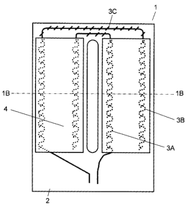
Fig. 1A and Fig. 1B are a plan view and a sectional view of a sheet
heating element in accordance with a first exemplary embodiment of the
present invention. Fig. 2 and Fig. 3 are a side view and a front view showing
a vehicle seat mounted with the sheet heating element shown in Fig. 1A.
Sheet heating element 1 includes electrically insulative substrate 2 and
first electrode (hereinafter referred as "electrode") 3A, second electrode
(hereinafter referred as "electrode") 3B, and polymer resistor 4. Electrodes
3A,
3B are often described as electrodes 3 in the following. Electrodes 3A, 3B are
CA 02642012 2008-08-08
9
disposed on substrate 2 in a bilaterally-symmetric fashion to each other and
partially sewed on substrate 2 by thread 3C. Polymer resistors 4 are formed
on substrate 2 with electrodes 3 disposed thereon, which are extruded in the
form of film by a T-die extruding method. As a result, polymer resistor 4 is
fusion-bonded on electrodes 3 and substrate 2.
The central portion of sheet heating element 1 is punched after
fusion-bonding polymer resistors 4 onto electrodes 3 and substrate 2. Sheet
heating element 1 is configured in this way. Lead wires for supplying power
from a power source to electrodes 3A, 3B are not shown. In addition, the
punching portion is not limited to the central portion. It is allowable to
punch
other portion depending upon the material and shape of surface skin 10 of the
seat. In that case, the wiring pattern of electrodes 3 may be changed.
In this configuration, unlike the conventional sheet heating element
configured in five layers with a substrate, polymer resistor, fusion-bonding
resin, and coating material, sheet heating element 1 is configured in three
layers with substrate 2, a pair of electrodes 3, and polymer resistors 4.
Accordingly, it is easier to display flexibility and to assure lower cost.
Also, electrodes 3 are sewed on substrate 2. In this configuration, the
material cost can be reduced, but greater man-hour is required for processing.
However, the processing cost can also be reduced when manufactured in a
district where the processing rate is lower.
Polymer resistor 4 is electrically connected to electrodes 3 by a
fusion-bonding method. In this way, electrodes 3 and polymer resistors 4, and
substrate 2 and polymer resistors 4 are respectively connected to each other
by
a fusion-bonding method. As a result, electrodes 3 are disposed between
substrate 2 and polymer resistor 4 in a state of being electrically connected
with electrodes 3.
Substrate 2 is, for example, needle punch type non-woven fabric made
CA 02642012 2008-08-08
of polyester fiber. It is preferable to use woven fabric other than this. It
is
preferable that substrate 2 is impregnated with flame retardant and given
incombustibility.
Electrodes 3 are formed of tin-plated twisted copper wires having a
5 resistance value of 0.03 ohm/cm or less, for example. Other than this, it is
also preferable to use braided copper wires after plated. In this way, using
the
plated and twisted copper wires or the plated and braided copper wires to form
electrodes 3, it is possible to make electrodes 3 inexpensive and excellent in
flexibility.
10 Also, electrodes 3 are preferable to be disposed in a wave-form fashion
as shown in Fig. 1A. In this configuration, electrodes 3 are excellent in
flexibility because it has sufficient allowance for its length even when it is
expanded or deformed, thanks to the wave-form. Further, the electric
potential is equalized in a region corresponding to the wave width in polymer
resistor 4, and the heat generating portion of polymer resistor 4 becomes
uniform in quality.
Polymer resistor 4 is formed of a kneaded mixture of fibrous conductor
and resin composition. As the fibrous conductor, it is possible to use tin
plated
and antimony doped titanium oxide that is fibrous conductive ceramic, for
example. As the resin composition, for example, modified polyethylene having
carboxyl group as specific reaction resin that generates PTC characteristic,
modified polyethylene having epoxy group as reactive resin that reacts with
the
specific reaction resin, and ethylene vinyl alcohol copolymer as liquid-proof
resin component are respectively employed to be used in the form of a mixture.
Also, it is preferable to add a flame retardant to polymer resistors 4.
In this way, the combustibility of the resin composition can be reduced by the
flame retardant, and as a result, it is possible to realize the
incombustibility of
polymer resistors 4. As a flame retardant, it is possible to use a phosphoric
CA 02642012 2008-08-08
11
flame retardant such as ammonium phosphate and tricresyl phosphate, a nitric
flame retardant such as melamine, guanidine and guanyl urea, or a
combination of these. Also, it is possible to use an inorganic flame retardant
such as magnesium hydroxide and antimony trioxide, or a halogen flame
retardant of bromic or chloric type.
In the manufacture of polymer resistors 4, mixture A including the
specific reaction resin that generates PTC characteristic, the liquid-proof
resin,
and the fibrous conductor is previously prepared, while mixture B formed of
the
reactive resin and the flame retardant is previously prepared. And both of
them are mixed and extruded from a T-die into a film. Polymer resistors 4 are
manufactured in this way. The weight ratio of the fibrous conductor, resin
composition, and flame retardant is 35 : 5 : 60, for example, and the specific
reaction resin, the reactive resin, and the liquid-proof resin are used in
equal
quantity.
Sheet heating element 1 as a heater is mounted in seat 6 that is a seat
of a vehicle or in back rest 7 disposed so as to rise from seat 6, so as to
dispose
substrate 2 on the surface side thereof. Seat substrate 9 and surface skin 10
are used for seat 6 and back rest 7. Seat substrate 9 such as urethane pad
changes in shape when a load is applied by the person taking the seat, and
restores its original shape when the load is released. Seat substrate 9 is
covered with surface skin 10. That is, sheet heating element 1 is mounted
with polymer resistors 4 disposed on the seat substrate 9 side, and substrate
2
on the surface skin 10 side. In order to correspond to a hanging portion (not
shown) of seat 6 or back rest 7, there is sometimes provided an extension (not
shown) of substrate 2 for the hanging purpose at the central portion or
peripheral portion.
In this way, thin sheet heating element 1 is disposed along seat
substrate 9 and surface skin 10 which may change in shape. Accordingly,
CA 02642012 2008-08-08
12
sheet heating element 1 similarly has to change in shape in accordance with
the deformation of seat 6 and back rest 7. Therefore, it is necessary to
design
various heating patterns and to change the position of electrodes 3 to achieve
the purpose. Here, the detailed description is omitted.
A pair of wide electrodes 3A, 3B disposed so as to be opposed to each
other are disposed along the outer portion in the lengthwise direction of
sheet
heating element 1. Power is supplied from electrodes 3A, 3B to polymer
resistors 4 disposed so as to be placed on electrode 3A, 3B, and thereby, the
current flows in polymer resistors 4, and then polymer resistors 4 generate
heat.
Polymer resistor 4 has PTC characteristic, thus it displays a
self-temperature controlling function to adjust the temperature to a specific
level when the temperature rises causing the resistance value to increase.
That is, polymer resistors 4 provide sheet heating element 1 with excellent
safety and a function of making temperature control unnecessary. Also, as a
vehicle seat heater mounted in a vehicle seat, sheet heating element 1 is able
to
satisfy the requirements for the feel of the seat, incombustibility, and
liquid-proof property. The requirement for the feel of the seat can be
satisfied
when the element is free from causing paper wrinkling noise, and equivalent in
elongation characteristic to the seat skin material, that is, the load is less
than
7 kgf as against 5% elongation.
Also, as compared with a conventional tubing heater, sheet heating
element 1 having PTC characteristic is able to display quick heating and
energy saving abilities. A tubing heater required a temperature controller.
Such a temperature controller serves to turn the power ON/OFF to control the
heating temperature of the tubing heater. Since the heater temperature with
power turned ON increases to about 80 C, it is necessary to dispose the
heater
a certain distance apart from surface skin 10. In the case of sheet heating
CA 02642012 2008-08-08
13
element 1, on the other hand, the heating temperature is self-controlled
within
a range of 40 C to 45 C. Accordingly, it is possible to dispose sheet
heating
element 1 in a position close to surface skin 10. Since sheet heating element
1
is low in heating temperature and can be disposed in the vicinity of surface
skin 10, it is possible to ensure quick heating and to reduce externally
discharging losses of heat. Accordingly, it is possible to meet the
requirement
for energy saving.
Further, sheet heating element 1 can be provided with incombustibility
by using incombustible non-woven fabric for substrate 2, and also, by using an
incombustible fibrous conductor for polymer resistor 4 and mixing a flame
retardant therein as needed. Sheet heating element 1 itself is required to
satisfy the incombustibility specified in U.S. Standards for Incombustibility
of
Motorcar Interior FMVSS302, and it is possible to satisfy the requirement by
disposing substrate 2 made of incombustible non-woven fabric on the upper
side of the seat. In FMVSS302 standards, the outline of incombustibility is
defined as follows. That is, the specimen does not catch fire even when a gas
burner is applied to the surface thereof in a box-like testing device, or
within
the range of a half inch in thickness from the surface, the flame does not
spread at a speed of over 4 inches per minute. Also, in the case of extinction
within 60 seconds, it does not extend more than 2 inches from the firing
point.
Accordingly, those that are self-extinction type as well as being
incombustible or less than 80 mm/minute in burning speed under the condition
of horizontal firing conform to the standards. That is, incombustibility means
that when a gas flame is applied to an end of the specimen, and the gas flame,
the firing source, is extinguished 60 seconds later, the fired portion of the
specimen is charred but free from burning. Also, self- extinction means that
even when the specimen is fired, it goes out within 60 seconds and within 2
inches.
CA 02642012 2008-08-08
14
Further, it is preferable to use a fibrous or flake-like conductor for
polymer resistors 4. In this way, the resistance value stability will be
enhanced. The PTC generating mechanism of polymer resistor 4 is supposed
to be as follows. Fig. 4A to Fig. 4D are conceptual diagrams for describing
the
PTC generating mechanism. In Fig. 4A and Fig. 4B, granular conductor 34
such as carbon black is used, and in Fig. 4C and Fig. 4D, fibrous conductor 39
is used.
In the case of polymer resistor 35 using granular conductor 34 such as
carbon black as conductor, as shown in Fig. 4A, granular conductor 34 has a
structure but its conduction path is in a state of so-called grain-to-grain
point
contact. Therefore, when a current is applied between electrodes 31, 32, resin
composition 33 generates heat as shown in Fig. 4B, and the heat causes the
conduction path to sensitively break due to the change in specific volume.
Thus, resistance temperature characteristics including rapid increase in
resistance value are generated.
On the other hand, fibrous conductor 39 is used for polymer resistors 4.
Consequently, as shown in Fig. 4C, the contact points of the conduction path
formed are increased. Therefore, the conduction path is maintained as the
change in specific volume is very slight. However, in the case of great change
in specific volume at the melting point, for example, resistance temperature
characteristics of generating great change in resistance value are generated
the
same as for carbon black. Thus, in the case of polymer resistor 4, the
stability
of resistance value is enhanced because of the increase of contact points due
to
overlap of fibrous conductors 39 as against the hysteresis of specific volume
in
accordance with crystallization of resin composition 38 that generates PTC
characteristic.
Further, it is preferable to mix the liquid-proof resin in resin
composition 38 of polymer resistors 4. In this way, it is possible to provide
CA 02642012 2008-08-08
polymer resistors 4 with liquid-proof property. Liquid-proof property stands
for resistance stability when various kinds of liquids such as engine oil
being
non-polar oil, brake oil being polar oil, and organic solvents such as thinner
having low molecule come into contact with polymer resistors 4. Other than
5 ethylene vinyl alcohol copolymer, it is possible to use thermoplastic
polyester
resin, polyamide resin, and polypropylene resin, individually or in
combination
as the liquid-proof resin.
In order to satisfy the elongation characteristic required for sheet
heating element 1 built into a seat, it is necessary to include flexible
polymer
10 resistors 4 and flexible resin composition 38 thereof. To have flexibility
means
that flexible resin composition 38 is non- crystalline. Generally,
non-crystalline resin is easily swelled when it comes into contact with
liquids of
various kinds and changes in specific volume. This causes the resistance
value to increase just like as for the change in specific volume due to heat.
15 When resin composition having no liquid-proof property is used for the
polymer
resistor, and the resin composition is swelled, the polymer resistor will not
easily restore its resistance value, thus generates no heat. Accordingly, it
is
preferable to add highly crystalline liquid-proof resin to resin composition
38.
Thus, due to the reactive resin having flexibility, the specific reaction
resin
that generate PTC characteristic, the fibrous conductor, and the liquid-proof
resin are partially chemically bonded to each other. As a result, the
liquid-proof property of polymer resistor 4 can be greatly improved. In the
case of polymer resistors 4 configured in the above-mentioned mixing ratio, it
is
possible to sufficiently satisfy the liquid-proof property standard. More
specifically, the change in resistance value before and after a test is +50%
or
less when power is supplied for 24 hours after the lapse of 24 hours after
dropping liquids of various kinds, which is thereafter left at the room
temperature for 24 hours.
CA 02642012 2008-08-08
16
As a combination of the functional group of reactive resin and specific
reaction resin of resin composition 38, the following combination is possible
other than the epoxy group and carboxylic acid group.
Epoxy group reacts with carbonyl group such as maleic anhydride
group, ester group, hydroxyl group, amino group, etc. other than the
carboxylic
acid group for addition polymerization. It is preferable to use specific
reaction
resin having one of such functional groups. Also, it is possible to use
oxazolic
group or maleic anhydride group as reactive functional group. Thus, resin
composition 38 has a structure cross-linked via at least one of oxygen atom
and
nitrogen atom. The reactive functional group of the reactive resin reacts with
the functional group of specific reaction resin that is a polar group for
providing
chemical-bonding. Accordingly, it is possible to enhance the thermal stability
as compared with the case of using only specific reaction resin.
In this way, since resin composition 38 includes the reactive resin and
the specific reaction resin that generates PTC characteristic, fibrous
conductor
39 can be caught by the adhering and bonding force of the reactive resin.
Further, the conduction path of fibrous conductor 39 becomes stabilized by the
bonding force between the reactive resin and the specific reaction resin.
When the heating temperature is as relatively low as 40 to 50 C as in a
vehicle seat heater, it is preferable to use ester ethylene copolymer such as
ethylene vinylacetate copolymer, ethylene acrylethyl copolymer, or ethylene
methyl metacrylate coplymer, which is low melting-point resin, as specific
reaction resin that generates PTC characteristic. Other than those, it is also
possible to use reactive resin as the specific reaction resin when the heat
generating temperature is appropriate.
As fibrous conductor 39, other than titanium oxide type conductive
ceramic fiber, it is preferable to use potassium titanate type conductive
ceramic
whisker or conductive ceramic fiber, metallic fiber such as copper and
CA 02642012 2008-08-08
17
aluminum, insulative ceramic fiber formed with conductive layer on the surface
such as metal-plated glass fiber, carbon fiber such as PAN type carbon fiber,
carbon nano-tube, or fibrous conductive polymer formed of polyaniline. Also,
it is preferable to use flake-like conductor in place of fibrous conductor 39.
As
the flake-like conductor, it is possible to use conductive ceramic whisker or
metal flake, insulative ceramic flake or whisker formed with conductive layer
on the surface such as metal-plated mica flake, or flaky graphite. Also, from
the view point of realizing the incombustibility of polymer resistors 4, it is
preferable to use incombustible material such as metal and ceramic.
Next, a preferable structure for equalizing the potential distribution in
polymer resistors 4 is described in the following. Fig. 5A is a plan view of
another sheet heating element in the present exemplary embodiment. Fig. 5B
is a sectional view along the line 5B - 5B in Fig. 5A. In this configuration,
there are provided a plurality of auxiliary electrodes 5 between electrodes
3A,
3B. The configuration other than this is same as in Fig. 1A and Fig. 1B.
In the configuration of Fig. 1A, a portion between electrodes 3A and 3B
may be partially thermally insulated, thus the resistance value thereof may be
increased, resulting in concentration of the potential depending upon the
condition. If the condition goes on, the temperature of the part of polymer
resistors 4 will become higher than that of other portions, that is, there
arises a
so-called hot line phenomenon. As in Fig. 5A, the generation of hot line can
be
avoided with the potential equalized by disposing auxiliary electrode 5. As a
result, the safety of sheet heating element 1 is enhanced.
For auxiliary electrode 5, it is preferable to use tin-plated twisted
copper wire or tin-plated braided copper wire which is the same as for
electrode
3, and it is preferable to adopt a wave-form configuration. The number of
auxiliary electrodes 5 is not limited. It is allowable to decide the number of
auxiliary electrodes 5 according to the size of polymer resistor 4, using more
CA 02642012 2008-08-08
18
than one. That is, at least a pair of auxiliary electrodes 5 are disposed
parallel
with electrodes 3, and are electrically connected to polymer resistors 4.
A different arrangement and structure of polymer resistors 4,
electrodes 3, and substrate 2 will be described in the following. Fig. 6A is a
plan view of further another sheet heating element in the present exemplary
embodiment. Fig. 6B is a sectional view along the line 6B - 6B in Fig. 6A. In
this configuration, polymer resistors 4 are thermally laminated on substrate 2
in the form of film, and thereafter, electrodes 3 are sewed thereon. And they
are heated under pressure in order to ensure the electrical connection between
electrodes 3 and polymer resistor 4. That is, electrodes 3 are exposed from
polymer resistor 4. The materials for the component elements are same as in
the configuration of Fig. 1A.
Also in this configuration, the same as in the configuration of Fig. IA,
sheet heating element 1 can be obtained as a vehicle seat heater. Also, in the
configuration of Fig. 1A, electrodes 3 are located between substrate 2 and
polymer resistors 4, while in the configuration of Fig. 6A, electrodes 3 are
located on polymer resistor 4. Therefore, it is easy to confirm the position
of
electrodes 3, and the central portion of substrate 2 can be reliably punched
for
the purpose of increasing the flexibility. Also, because of freedom for the
arrangement of electrodes 3, the process of affixing polymer resistors 4 to
substrate 2 can be performed in common when manufacturing sheet heating
elements of various heating patterns. It is also preferable to provide this
configuration with auxiliary electrodes 5 shown in Fig. 5A.
A preferable structure for enhancing the flexibility of sheet heating
element 1 will be described in the following. Fig. 7A is a plan view of
another
sheet heating element in the present exemplary embodiment. Fig. 7B is a
sectional view along the line 7B - 7B in Fig. 7A. In this configuration,
slidable
conductors 11 are previously disposed on polymer resistors 4, and thereafter,
CA 02642012 2008-08-08
19
electrodes 3 are disposed on slidable conductors 11. The other configurations
are same as in Fig. 6A. Slidable conductor 11 is, for example, a film prepared
by drying a paste using graphite or a film of resin compound prepared by
kneading graphite.
In this configuration, since electrode 3 slides on slidable conductor 11,
the flexibility of sheet heating element 1 is enhanced, also the electrical
connection between electrodes 3 and polymer resistor 4 becomes more reliable.
It is preferable to provide this configuration with auxiliary electrodes 5
shown
in Fig. 5A. Also, it is preferable to dispose slidable conductors 11 in the
positions where auxiliary electrodes 5 are disposed.
Another preferable structure for enhancing the flexibility of sheet
heating element 1 will be described in the following. Fig. 8A is a plan view
of
another sheet heating element in the present exemplary embodiment. Fig. 8B
is a sectional view along the line 8B - 8B in Fig. 8A. In this configuration,
polymer resistors 13 are used in place of polymer resistors 4. Polymer
resistors 13 are manufactured by impregnating mesh-like non-woven fabric or
woven fabric having openings with ink formed from the same material for
polymer resistor 4, followed by drying. The configurations other than this are
same as in Fig. 6A.
In this configuration, polymer resistor 13 has the openings and is
changeable in shape. Accordingly, sheet heating element 1 using polymer
resistor 13 becomes more flexible.
In the above embodiment, electrodes 3 and polymer resistor 4, 13 are
thermally bonded to each other, but the present invention is not limited to
this.
Electrodes 3 and polymer resistor 4, 13 can be electrically connected to each
other by bonding via conductive adhesive or just by pressing them against each
other to make mechanical contact. Further, it is preferable to dispose a
coating layer on polymer resistors 4, 13, electrodes 3 or auxiliary electrodes
5
CA 02642012 2008-08-08
on the opposite side of substrate 2 for the purpose of enhancing the wear
resistance. The coating layer is preferable to cover at least polymer
resistors 4
that is lower in strength. Considering flexibility, it is preferable to use a
thin
coating layer. Also, a thinner coating layer can be used as compared with the
5 conventional one because the electrodes have excellent weather resistance.
It is preferable to dispose sheet heating element 1 thus configured on
seat 6 or back rest 7 so that substrate 2 is on the surface side. That is,
substrate 2 serves as a cushion, and therefore, the feel of the seat is not
affected because the thickness and hardness of electrodes 3 or auxiliary
10 electrodes 5 are felt on the seat surface. Also, using incombustible non-
woven
fabric as substrate 2 and disposing it on the surface side, spreading of fire
in
the combustion test can be prevented, and it is possible to obtain a practical
seat.
Second exemplary embodiment
15 Fig. 9A and Fig. 9B are respectively a plan view and a sectional view of
a sheet heating element in accordance with a second exemplary embodiment of
the present invention. The difference from the configuration of Fig. 1A and
Fig. 113 in the first exemplary embodiment is such a point that liquid-proof
film
12 is affixed on substrate 2, and electrodes 3 are sewed on liquid-proof film
12.
20 Also, the resin composition of polymer resistor 4 is a combination of the
specific
reaction resin that generates PTC characteristic and the reactive resin. The
configurations other than those are same as in Fig. 1A and Fig. 1B in the
first
exemplary embodiment.
In the present exemplary embodiment, liquid-proof film 12 is disposed
in the direction of penetration of the liquid, that is, on the substrate 2
side.
Accordingly, polymer resistors 4 are suppressed from coming in contact with
the liquid, and consequently, the liquid-proof property of sheet heating
element
1 is enhanced. In this configuration as well, the standard for liquid-proof
CA 02642012 2008-08-08
21
property can be satisfied the same as in the first exemplary embodiment.
Due to this configuration, unlike the conventional sheet heating
element formed of five layers of a substrate, electrodes, a polymer resistor,
a
fusion-bonding resin, and a coating material, sheet heating element 1 is
formed
of four layers of substrate 2, liquid-proof film 12, a pair of electrodes 3,
and
polymer resistors 4. Accordingly, it is easier to display flexibility, and
lower in
cost.
Liquid-proof film 12 is preferable to be formed from incombustible
material having incombustibility at least defined in the FMVSS302 standards.
Thus, the incombustibility of sheet heating element 1 is enhanced. As such an
incombustible material, ethylene vinyl alcohol copolymer, plastic polyester
resin, polyamide resin, and polypropylene resin can be used individually or in
combination.
As same as in Fig. 5A and Fig. 5B of the first exemplary embodiment,
the case of providing the configuration of Fig. 9A and Fig. 9B with auxiliary
electrodes 5 will be briefly described in the following. Fig. 1OA is a plan
view
of another sheet heating element in the present exemplary embodiment, and
Fig. 10B is a sectional view along the line lOB - lOB.
Thus, providing the configuration of Fig. 9A with auxiliary electrode 5
between electrodes 3 as same as in Fig. 5A of the first exemplary embodiment,
it is possible to avoid the generation of hot line. As a result, the safety of
sheet
heating element 1 can be further enhanced.
Next, the case of disposing electrodes 3 on polymer resistor 4 as same
as in Fig. 6A and Fig. 6B of the first exemplary embodiment will be briefly
described. Fig. 11A is a plan view of further another sheet heating element in
the present exemplary embodiment, and Fig. 11B is a sectional view along the
line 11B - 11B.
Polymer resistors 4 are laminated in the form of film on liquid-proof
CA 02642012 2008-08-08
22
film 12, followed by sewing electrodes 3 thereon. And they are heated under
pressure in order to make the electrical connection between electrodes 3 and
polymer resistor 4 more reliable. In this way, the same as in the
configuration
shown in Fig. 6A and Fig. 6B of the first exemplary embodiment, sheet heating
element 1 as a vehicle seat heater can be obtained as well. And, the same
effects as in Fig. 6A and Fig. 6B of the first exemplary embodiment can be
obtained. It is preferable to provide this configuration with auxiliary
electrodes 5 shown in Fig. 10A.
Next, the same as in Fig. 7A and Fig. 7B of the first exemplary
embodiment, the case of disposing slidable conductors 11 will be briefly
described. Fig. 12A is a plan view of another sheet heating element in the
present exemplary embodiment, and Fig. 12B is a sectional view along the line
12B - 12B.
As described above, slidable conductors 11 are previously disposed on
polymer resistors 4, and electrodes 3 are disposed thereon. Accordingly,
electrode 3 can slide on slidable conductor 11, further enhancing the
flexibility
of sheet heating element 1. Also, the electrical connection between electrodes
3 and polymer resistor 4 becomes more reliable. That is, the same effects as
in
Fig. 7A and Fig. 7B of the first exemplary embodiment can be obtained. It is
preferable to provide this configuration with auxiliary electrodes 5 shown in
Fig. 10A.
Next, the same as in Fig. 8A and Fig. 8B of the first exemplary
embodiment, the case of using polymer resistors13 in place of polymer
resistors
4 will be briefly described. Fig. 13A is a plan view of further another sheet
heating element in the present exemplary embodiment, and Fig. 13B is
sectional view along the line 13B - 13B.
Polymer resistor 13 is manufactured by impregnating mesh-like
non-woven fabric or woven fabric having openings with ink formed from the
CA 02642012 2008-08-08
23
same material for polymer resistor 4, followed by drying. In this
configuration,
polymer resistor 13 has openings and is changeable in shape. Accordingly,
sheet heating element 1 using polymer resistor 13 becomes more flexible.
That is, the same effects as in Fig. 8A and Fig. 8B of the first exemplary
embodiment can be obtained.
It is preferable to dispose sheet heating element 1 thus configured on
seat 6 or back rest 7 shown in Fig. 2 and Fig. 3 so that substrate 2 is on the
surface side. That is, substrate 2 serves as a cushion, and therefore, the
feel of
the seat is not affected because the thickness and hardness of electrodes 3 or
auxiliary electrodes 5 are felt on the seat surface. Also, using incombustible
non-woven fabric as substrate 2 and disposing it on the surface side,
spreading
of fire in the combustion test can be prevented, and it is possible to obtain
a
practical seat. That is, it is preferable to dispose sheet heating element 1
in
the present exemplary embodiment on seat 6 or back rest 7 as well as in the
first exemplary embodiment.
Third exemplary embodiment
Fig. 14A and Fig. 14B are respectively a plan view and a sectional view
of a sheet heating element in the exemplary embodiment of the present
invention. The difference from the configuration of Fig. 1A and Fig. 1B in the
first exemplary embodiment is such a point that at least one of substrate 2
and
polymer resistor 4 is provided with slits 15. Slit 15 serves as a deformation
absorbing portion that absorbs deformation generated by external forces. The
configurations other than this are same as in Fig. 1A and Fig. 1B of the first
exemplary embodiment.
In the present exemplary embodiment, the same as in the first
exemplary embodiment, electrodes 3A, 3B are sewed on substrate 2, and
polymer resistors 4 are extruded in the form of film by means of T-die
extrusion
method, then polymer resistors 4 are thermally fusion-bonded onto electrodes 3
CA 02642012 2008-08-08
24
and substrate 2. And after the central portion of substrate 2 is punched,
polymer resistors 4 are punched by Thomson punch in the positions between
electrodes 3A and 3B, and thereby, there are provided slits 15 that penetrate
from polymer resistor 4 to substrate 2.
The portions to be punched by Thomson punch are not limited to those
positions. It is allowable to punch other portions in accordance with the
surface skin condition of the seat. In that case, it is necessary to change
the
wiring patterns of electrodes 3, but there is no problem with this. The
punched portion at the center can also be considered as a deformation
absorbing portion, but the central portion is often punched because of the
surface skin shape of the seat and it is discriminated as a deformation
absorbing portion.
It is also allowable to extrude polymer resistors 4 in the form of film by
means of T-die extrusion method onto substrate 2 provided with slits 15
previously formed by punching by Thomson, followed by fusion-bonding of
polymer resistors 4 onto electrodes 3 and substrate 2. Or, it is allowable to
extrude polymer resistors 4 as films by means of T-die extrusion method on a
separator (not shown) made of polypropylene, release paper or the like, and to
make slits 15 in polymer resistors 4 by punching. Slits 15 are formed only in
substrate 2 in the former case, and only in polymer resistors 4 in the latter
case.
As described above, sheet heating element 1 in the present exemplary
embodiment is provided with slits 15 that are the deformation absorbing
portions for absorbing deformation generated by external forces. Accordingly,
sheet heating element 1 is easy to change its shape against external forces
and
may provide a satisfactory feel of the seat.
A deformation absorbing portion that is different from slit 15 will be
described in the following. Fig. 15A is a plan view of another sheet heating
CA 02642012 2008-08-08
element in the present exemplary embodiment. Fig. 15B is a sectional view
along the line 15B - 15B. The difference of the configuration in Fig. 15A and
Fig. 15B from the configuration in Fig. 14A and Fig. 14B is such a point that
there are provided notches 15A as deformation absorbing portions.
5 In this case, polymer resistors 4 are formed as films by means of T-die
extrusion method on a separator (not shown) such as polypropylene and release
paper, and at this stage, notches 15A are formed in polymer resistors 4 by
punching. Subsequently, by using a heat laminator, polymer resistors 4 are
affixed on substrate 2 provided with electrodes 3, followed by removing the
10 separator to make sheet heating element 1.
In this configuration as well, electrodes 3 and polymer resistor 4 are
fusion-bonded to each other, and thereby, it is possible to establish
electrical
connection and also to provide a satisfactory feel of the seat due to notches
15A
that are the deformation absorbing portions.
15 Next, the same as for Fig. 5A and Fig. 5B in the first exemplary
embodiment, the case of the configuration with auxiliary electrodes 5 will be
briefly described. Fig. 16A is a plan view of another sheet heating element in
the present exemplary embodiment, and Fig. 16B is a sectional view along the
line 16B - 16B. In this case, when slits 15 are formed by punching polymer
20 resistors 4 and substrate 2, a part of each auxiliary electrode 5 is also
punched.
Thus, providing the configuration of Fig. 14A with auxiliary electrodes
5 between electrodes 3 the same as in Fig. 5A and Fig. 5B of the first
exemplary embodiment, it is possible to avoid the generation of hot line. As a
result, the safety of sheet heating element 1 can be further enhanced.
25 Next, the case of disposing electrodes 3 on polymer resistor 4 as same
as in Fig. 6A and Fig. 6B of the first exemplary embodiment will be briefly
described. Fig. 17A is a plan view of further another sheet heating element in
the present exemplary embodiment, and Fig. 17B is a sectional view along the
CA 02642012 2008-08-08
26
line 17B - 17B.
As shown, polymer resistors 4 are laminated in the form of films on
substrate 2, electrodes 3 are sewed thereon, and they are heated under
pressure in order to make the electrical connection between electrodes 3 and
polymer resistor 4 more reliable. After that, polymer resistors 4 and
substrate
2 are punched to form slits 15. In this configuration, the same effect as in
Fig.
6A and Fig. 6B of the first exemplary embodiment can be further obtained. It
is preferable to provide this configuration with auxiliary electrodes 5 shown
in
Fig. 16A.
Next, the same as in Fig. 7A and Fig. 7B of the first exemplary
embodiment, the case of disposing slidable conductors 11 will be briefly
described. Fig. 18A is a plan view of another sheet heating element in the
present exemplary embodiment, and Fig. 18B is a sectional view along the line
18B - 18B.
As described above, slidable conductors 11 are previously disposed on
polymer resistor 4, and electrodes 3 are disposed thereon. Accordingly,
electrode 3 can slide on slidable conductor 11, further enhancing the
flexibility
of sheet heating element 1. Also, the electrical connection between electrodes
3 and polymer resistor 4 becomes more reliable. That is, the same effects as
in
Fig. 7A and Fig. 7B of the first exemplary embodiment can be further obtained.
It is preferable to provide this configuration with auxiliary electrodes 5
shown
in Fig. 16A.
Next, the same as in Fig. 8A and Fig. 8B of the first exemplary
embodiment, the case of using polymer resistors 13 in place of polymer
resistors 4 will be briefly described. Fig. 19A is a plan view of further
another
sheet heating element in the present exemplary embodiment, and Fig. 19B is a
sectional view along the line 19B - 19B.
Polymer resistors 13 are manufactured by impregnating mesh-like
CA 02642012 2008-08-08
27
non-woven fabric or woven fabric having openings with ink formed from the
same material for polymer resistor 4, followed by drying. In this
configuration,
polymer resistors 13 have the openings and are changeable in shape.
Accordingly, sheet heating element 1 using polymer resistors 13 becomes more
flexible. That is, the same effects as in Fig. 8A and Fig. 8B of the first
exemplary embodiment can be further obtained.
Next, a configuration with electrodes 3 disposed on another electrically
insulative substrate will be described. Fig. 20A is a plan view of further
another sheet heating element in the present exemplary embodiment. Fig.
20B is a sectional view along the line 20B - 20B. In this configuration,
insulative second substrate 14 with electrodes 3 sewed thereon and substrate 2
with polymer resistors 4 affixed thereon are thermally laminated and affixed
to
each other, thereby forming sheet heating element 1. Consequently, second
substrate 14 is disposed opposite to the surface where substrate 2 of sheet
heating element 1 is disposed. Electrodes 3 are fixed on second substrate 14.
In this configuration, polymer resistors 4 and electrodes 3 can be
handled as parts separate from each other. Accordingly, it is possible to make
the deformation absorbing portions, namely slits 15 or notches 15A shown in
Fig. 15A in proper portions or to use them in combination. That is, in this
configuration, a deformation absorbing portion can be formed in at least one
of
substrates 2, 14 and polymer resistors 4. In this way, it is possible to
obtain
sheet heating element 1 which may change its shape against external forces to
provide an excellent feel of the seat.
Also, disposing second substrate 14 so as to cover at least polymer
resistors 4, it serves as a coating layer described in the first exemplary
embodiment.
Sheet heating element 1 in the present exemplary embodiment, having
the configuration as described above, is preferable to be arranged in seat 6
or
CA 02642012 2008-08-08
28
back rest 7 shown in Fig. 2, Fig. 3 so that substrate 2 is disposed on the
surface
side. That is, substrate 2 serves as a cushion, and therefore, the feel of the
seat is not affected because the thickness and hardness of electrodes 3 or
auxiliary electrodes 5 are felt on the seat surface. Also, using incombustible
non-woven fabric as substrate 2 and disposing it on the surface side,
spreading
of fire in the combustion test can be prevented, and it is possible to obtain
a
practical seat. That is, sheet heating element 1 in the present exemplary
embodiment is also preferable to be used in seat 6 or back rest 7 the same as
for the first exemplary embodiment.
INDUSTRIAL APPLICABILITY
The sheet heating element of the present invention has a simple
structure and is flexible enough to absorb deformation generated due to
external forces. The sheet heating element can be mounted on the surface of
an apparatus having continuously curved surfaces or combined planes, for
example. Accordingly, it can be used as a heater for a vehicle seat, steering
wheel, or other apparatus necessary to be heated.