Note: Descriptions are shown in the official language in which they were submitted.
CA 02642062 2008-10-27
CONTAINER
100011 This application claims priority to U.S. Provisional Application Serial
Nos.
60/982,581, filed October 25, 2007 and 61/022,178, filed January 18, 2008.
BACKGROUND
100021 The present invention relates generally to containers with removable
lids, in
particular, containers and lids that are particularly useful for disposing of
medical products.
SUMMARY
(00031 The present invention provides a plurality of various individually
inventive
containers, which are described in detail below and shown in the drawings.
Additionally, the
present invention provides an inventive group or system of containers and
system and method for
making a plurality of different containers from a minimum number of molds,
with some inserts.
Generally, multiple container sizes can be provided from the same mold
utilizing inserts to
reduce the size of the mold.
100041 In one embodiment, to accommodate various lid designs, the present
invention
provides a rim that is connected to the upper edge of the container. The rim
can be formed in
various configurations (described below) from a single mold using mold
inserts. The various rim
configurations accommodate different lids. Providing the mold inserts on the
rim (which is a
very shallow part) is much simpler than providing such inserts on the
container itself.
100051 These and other features of the application can be best understood from
the
following specification and drawings, the following of which is a brief
description.
CA 02642062 2008-10-27
BRIEF DESCRII'TION OF THE DRAWINGS
100061 Figure 1 is a perspective view of a container according to a first
embodiment.
[0007[ Figure 2 is a perspective view of a container according to a second
embodiment, nested in a similar container.
100081 Figure 3 illustrates the container of Figure 2 with the lid removed.
[0009] Figure 4 is an enlarged view of the hinge area of the container of
Figure 2.
[0010] Figure 5 is bottom perspective view of an alternate version of the
container of
Figure 2.
100111 Figure 6 illustrates an alternate lid.
100121 Figure 7 is a perspective view of a container according to a third
embodiment
and alternate lid.
100131 Figure 8 illustrates the container of Figure 7 with the lid open.
[0014] Figure 9 illustrates a container assembly according to a fourth
embodiment.
[0015] Figure 10 illustrates the container assembly in another position.
[0016] Figure 11 A is a perspective view of the base of Figure 9.
[0017] Figure 11 B is a side perspective view of the base of Figure 1 IA.
100181 Figure 11 C is a bottom perspective view of the base of Figure 11 A.
100191 Figure 1 1 D is a bottom view of the base of Figure 11 A.
[0020] Figure 12 is a perspective view of a plurality of stacked bases.
[0021] Figure 13 is an exploded view of the container of Figure 9 with a first
rim.
[0022] Figure 14 shows the first rim of Figure 13 mounted to the container.
100231 Figure 15 illustrates a jig for removing the rim from the container of
Figure
14.
2
CA 02642062 2008-10-27
100241 Figure 16 illustrates the container and rim of Figure 14 being inserted
into the
jig of Figure 15.
[00251 Figure 17 illustrates a first step in removing the rim from the
container with
the jig.
100261 Figure 18 illustrates a second step in removing the rim.
100271 Figure 19 illustrates a third step in removing the rim.
100281 Figure 20 illustrates the rim connected to a pair of lids on the
container.
100291 Figure 21 illustrates the rim and lids of Figure 20.
100301 Figure 22 is an exploded view of the rim and lids of Figure 21.
[00311 Figure 23 is an exploded view of the rim with an alternate crossbar and
lids.
[0032] Figure 24 is an assembled view of the rim and lids of Figure 23.
[00331 Figure 25 illustrates the container of Figure 9, a similar smaller
container and
a second rim.
100341 Figure 26 illustrates the second rim of Figure 25 with attached lids
secured to
the container.
[00351 Figure 27 is a perspective view of the second rim and open lids.
[00361 Figure 28 shows the second rim and lids with one lid closed.
[00371 Figure 29 shows the second rim and closed lids.
[0038] Figure 30 is an exploded view of a third rim and lids.
[00391 Figure 31 is an assembled view of the third rim and lids of Figure 30
in a
closed position.
[00401 Figure 32 illustrates the third rim and lids of Figure 3 I with the
lids open.
100411 Figure 33 illustrates a rim and lid according to another embodiment.
3
CA 02642062 2008-10-27
[00421 Figures 34A and 34B illustrate the rim and lid of Figure 33 in
different
positions during use.
100431 Figures 35-37 illustrate the rim and lid of Figure 32 with an alternate
tray.
100441 Figure 38 illustrates a container with a rim and lids according to
another
embodiment.
100451 Figure 39 shows the container of Figure 38 with the lids open.
[0046] Figure 40 is an exploded view of the rim and lids of Figure 38.
[0047] Figure 41 illustrates a container with a rim and lids according to
another
embodiment.
[00481 Figure 42 is an exploded view of Figure 41.
100491 Figure 43 shows the lid of Figure 41, partially broken away.
100501 Figure 44 shows the lid of Figure 31 during installation onto the rim
and
container.
DETAILED DESCRIPTION OF THE PREFERRED EMBODIMENTS
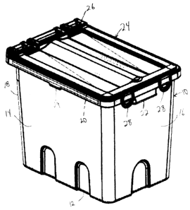
[00511 A container assembly for collecting medical waste according to a first
embodiment of the present invention is shown in Figure 1. The medical waste
could be
biological material, medical devices, etc. Some medical devices, such as metal
or Titanium-
containing devices may be recycled. 'I'he container assembly includes a
container 10 having a
base wall 12, side walls 14, a front wall 16 and a rear wall 18. A lip 20
protrudes outwardly
from the upper edge of the side walls 14, front wall 16 and rear wall 18.
Handles 22 protrude
outwardly from the front wall 16 and rear wall 18.
4
CA 02642062 2008-10-27
100521 A lid 24 is pivotably secured to the container 10 by a hinge 26. Front
latches
28 are integrally molded with the lid 24 and snap-fit to the lip 20 adjacent
the front wall 16.
Additional side latches 29 snap-fit to the lip 20 adjacent side walls 14. The
front latches 28 are
substantially difficult to unlatch by hand without a tool. A single front
latch 28 could be used
instead of two.
[0053] An alternate container assembly is shown in Figure 2 nested with a
similar
alternate container assembly. Each container assembly includes an alternate
container 110,
which is simply a taller version of the container 10 of Figure 1. The same lid
24 pivotably
attaches to the alternate container 110 in the same way.
100541 Figure 3 shows the alternate container 110 without the lid 24. The
upper end
of the container 10 of Figure 1 would be similar. At the upper end of the rear
wall 118, hinge
pins 134 protrude laterally lrom an upwardly protruding hinge support 132. The
side walls 114,
front wall 116 and rear wall 118 are similar to their counterparts in the
container 10 of Figure 1,
but taller.
[0055] Figure 4 illustrates the upper end of the container 110 with the lid 24
open.
The hinge pins 134 are snap-fit into hinge receivers 38 formed on the lid 24.
The connection to
the container 10 of Figure 1 would be similar.
[0056] A second alternate container 110A is shown in Figure 5. The second
alternate
container II 0A is identical to the container 110 of Figures 2-4, with the
exception of the base
wall 112A. The base wall 1 12A in Figure 5 includes a drag rail 140A
protruding downwardly
from the periphery of the base wall 112A. A plurality of ribs 142A extend
across the base wall
112A. A similar base wall 112A could be formed on the container 10 of Figure
1. Generally,
the base walls 12, 112 of the containers 10, 110 of Figures 1-4 could be used
with disposable
CA 02642062 2008-10-27
containers, while it might be preferable to use the base wall 112A with
reusable containers. In
fact, disposable and reusable versions of the containers could be formed in
the same mold, by
adding an insert into the mold that forms the drag rails 140A and ribs 142A.
[00571 Figure 6 illustrates an alternate lid 124. In Figure 6, the lid 124 is
shown on
container 110, but is interchangeable and could be used on containers 10,
110A, and any other
container in this application. The lid 124 is substantially similar to the lid
24 of Figure 1,
including front latches 128 and is pivotably connected to the container 110 by
a hinge 126.
However, the lid 124 includes a central opening 144 therethrough so that
medical waste can be
dropped into the container 110 through the opening 144. The lid 124 further
includes an
integrally molded cap 146 adapted to snap-fit to a peripheral rib around the
opening 144. The
cap 146 is connected to the lid 124 via an integrally molded tether 148. The
lid 124 of Figure 6
would have particular use for chemotherapy waste, such as syringes, platelets,
etc., in which case
the entire container assembly and contents may be periodically gathered and
incinerated.
[0058] An alternate container 210 and alternate lid 224 are shown in Figure 7.
Again,
all lids and containers in this application are interchangeably useable. The
alternate container
210 is identical to the container 1 10 and additionally includes wheels 50.
The wheels 50 are
within the envelope of the container 210 such that the container 210 is still
nestable within a
similar container 210 when empty.
100591 The lid 224 includes a rear portion 252 and a front portion 254
connected via
a living hinge 256. The side latches 229 secure the rear portion 252 to the
container 210, while
the front latches 228 further secure the front portion 254 to the container
210.
[0060] As shown in Figure 8, the front portion 254 of the lid 224 can be
opened
without opening the rear portion 252. Medical waste can be placed in the
container 210 via the
6
CA 02642062 2008-10-27
opened front portion 254, which can then be reclosed. As is also shown in the
lid 224, a gasket
256 may be formed around the periphery of the lid 224 so that it seals with
the container 210. Of
course, the gasket 256 could be formed on any of the lids disclosed in this
application. Similarly,
the wheels 50 could be used on any of the container disclosed in this
application. Again, this
container assembly could be made reusable or disposable.
100611 Figure 9 shows a container asseinbly including a container 310 and a
support
312. The support 312 includes a base portion 314 up from which extend a front
wall 316 and
rear wall 318, defining therebetween a channel 320. The container 310 may be
an injection
molded container 310 having end walls 322 and side walls 324 and a base wall
326 opposite a
container opening.
100621 The support 312 may optionally include castors 315, which may be snap-
fit or
otherwise removably secured to the support 312. The rear wall 318 of the
support 312 includes
spaced apart pillars 332 between which is defined a rear channel 330. As shown
in Figure 9, the
container 310 can be supported on the support 312, with the base wall 326 of
the container 310
received in the rear channel 330 and on the base portion 314 of the support
312 and secured
between the pillars 332. One end wall 322 is tilted toward the front wall 316.
In this position,
the container 310 is supported at an angle, with the base wall 326 supported
by rear wall 318.
[00631 The container 310 and support 312 can also be configured as shown in
Figure
10, in which the base wall 326 of the container 310 is disposed within the
channel 320 between
the front wall 316 and the rear wall 318 of the support 312. The side walls
324 are adjacent the
front wall 316 and rear wall 318. In this configuration, the support provides
stability to the
container 310 and may be used as a dolly with the optional castors 315.
7
CA 02642062 2008-10-27
(0064] The support 312 is also preferably injection molded from a
thermoplastic.
The support 312 is shown in more detail in Figures 11A-11D. Referring to
Figure 12, multiple
supports 312 can stack on one another and partially nest with one another to
reduce the overall
stacking height and increase the stability of the stack.
100651 The support 312 and container 310 arrangement is usable with all of the
embodiments of containers, lids, etc. described below.
100661 Referring to Figure 13, the container 310 may include a peripheral lip
335
protruding outwardly and then downwardly from upper most edges of the end
walls 322 and side
walls 324. At several locations, latches 336 are formed along the peripheral
lip 335. This
provides a removable connection to one of many optional rims, some of which
will be described
herein.
100671 The first rim 340 is shown in Figure 13 and includes a peripheral
portion 342
that is configured to fit over the peripheral lip 335 of the container 310.
The rim 340 further
includes latch portions 344 complementary to the latches 336 for removably
securing the rim 340
to the container 310. The rim 340 further includes a crossbar 346 forming a
chord across the
peripheral portion 342. Two sets of hinge receivers 348 are formed adjacent
openings in the rim
340 defined by the peripheral portion 342 and the crossbar 346.
10068] As shown in Figure 14, the rim 340 is snap-fit onto the container 310
via the
latch portions 344 and latches 336. The rim 340 (and any other rim described
herein) may be
secured to the container 310 over a plastic bag (not shown) inserted in the
container 310 and
draped over the upper edges of the container 310. If the rim 340 (or other
rims below) includes a
gasket, a leakproof seal can be provided at the rim/container interface with
or without using a
plastic bag.
8
CA 02642062 2008-10-27
100691 The rim 340 is designed such that it cannot easily be removed from the
container 310 by hand. Instead, ajig 350 is provided for removing the rim 40
from the container
310. The jig 350 is shown in Figure 15. The jig 350 may be metal, aluminum, or
injection
molded of a thermoplastic. The jig 350 includes a pcripheral portion 352 up
from which extend
a plurality of fingers 354 which are tapered to be received behind the latches
336, as shown in
Figure 16. When the container 310 is placed in the jig 350, the weight of the
container forces the
fingers 354 up behind the latches 336, as shown more clearly in Figures 17-19.
The taper of the
fingers 354 causes the latches 336 to deflect, thereby releasing the latches
336 from the latch
portions 344 of the rim 340 and the rim 340 can be removed from the container
310 and either
replaced (if damaged) or provided with a different type of rim (several
potential designs of which
are described herein). Because the jig 350 activates the latch from below, the
jig 350 does not
have to penetrate a lid or a rim to disengage the latch, which enhances the
ability to resist
leakage. The lids of Figures 1-8 could also be adapted to require the jig 350
for removal.
[0070] As shown in Figures 20-22, the rim 340 is connected to a pair of lids
360, 368
to form a lid assembly. The lids 360, 368 include integrally molded hinge
portions 362
complementary to the hinge receiver portions 348 on the rim 340. One of the
lids 360 includes
an opening 364 therethrough, through which objects, such as sharps or other
medical waste, can
be inserted. A secondary lid 366 is hingeably connected to the hinge portion
362 and hinge
receivers 348 to selectively cover the opening 364, as shown.
[0071] As shown in Figures 23 and 24, the rim 340 can also be provided with an
off-
center crossbar, which can occur with a different mold insert. This permits
the attachment of
different lids 370, 378. The lid 370 includes a large semicircular opening 372
having a matched
semicircular portion 374 having semi-annular recesses 375 for accommodating a
semicircular
9
CA 02642062 2008-10-27
door 376. The door 376 is rotatably connected to the semicircular portion 374
for selectively
closing the opening 372 through the lid 370.
[0072] Figure 25 illustrates the container 310 and a similar, smaller
container 410.
The smaller container 410 connects to the rims in the same manner as the
larger container 310.
The smaller container 410 can be made in the same mold as the container 310,
through the use of
mold inserts.
[0073] Figure 25 also illustrates a second rim 380 including a peripheral
portion 382
from which a plurality of hinge receivers 384 extend upwardly. The second rim
380 and
container 310 are shown in more detail in Figures 26-29. A pair of lids 386
having integrally
molded hinge portions 388 are hingeably connected to the hinge receiver
portions 384 on the
container 310. In this embodiment, the containers 310 with attached rims 380
and lids 386 can
be nested within similar containers 310 with attached rims 380 and lids 386,
thus reducing
shipping and storage space.
100741 Figures 30-32 illustrate a third rim 390 having a cross member 396 with
hinge
receivers 394 formed thereon. In this case, a pair of identical lids 397
having integrally molded
hinge portions 398 are connected to the hinge receivers 394 on the rim 390.
Again, the second
rim 390 can be selectively connected to the container 310 (with or without the
optional latch
portion 344, Figure 16).
[0075] Figures 33, 34A and 34B illustrate a third rim 400. The rim 400
includes a
peripheral portion 401 (for receiving the peripheral lip 335 of the container
310) and an upper
wall 403 in which is formed an opening 404. A tray 402 is hingeably connected
to the peripheral
portion 401 of the rim 400 in the opening 404. The tray 402 preferably
occupies all or
substantially all of the opening 404 in the at rest position as shown in
Figure 33 (i.e., the tray 402
CA 02642062 2008-10-27
pivots to this position due to gravity). The tray 402 includes an integrally
molded handle portion
405 protruding over a portion of the upper wall 403. In use, a user places an
object, such as a
used medical device, in the tray 402, then, using the handle 405, pivots the
tray 402 until the
object is dumped into the container (Figure 3413). When released, the tray
402, due to gravity,
then returns to it's at rest position, as shown in Figure 33.
[00761 An alternate tray 406 is shown in Figures 35-37. Whereas the tray 402
of
Figures 33, 34A-B was completely opened above a plane near the axis of
rotation of the tray 402,
the tray 406 extends almost 270 degrees about the axis of rotation. This
ensures that the opening
404 is always closed, no matter the position of the tray 406. A pair of
handles 408 are provided
to assist with dumping the tray 406 through the opening 404.
[0077] A fourth alternate rim 410 is shown in Figures 38-40. The rim 410
includes a
peripheral portion 412 having integrally molded hinge receivers 414. A pair of
identical lids 416
are hingeably connected to the hinge receivers 414 by integrally molded hinge
portions 418.
Each lid 416 includes a wide portion 420 extending across a midpoint of the
container 310 and a
narrow portion 422, complementary to the wide portion 420. This provides a
wider (squarer)
opening into the container 310 when only one lid 416 is flipped open. In this
embodiment, the
containers 310 with attached rims 410 and lids 416 can be nested within
similar containers 310
with attached rims 410 and lids 416, thus reducing shipping and storage space.
100781 An alternate assembly is shown in Figure 41-44, although certain
features
could be used in combination with those described above. An alternate
container 310' includes
integrally molded latch receivers 432 and an upper edge thereof around the
container opening. A
peripheral lip 446 protrudes outwardly and then downwardly from the upper edge
of the
container 310". A lid 430 includes a plurality of integrally molded hinge
portions 436 that are
11
CA 02642062 2008-10-27
received between the hinge receiver portions 432 and hingeably connected
thereto by an inserted
metal rod 434. The opposite edge of the lid 430 is fitted (prior to insertion
of the rod 434) onto
the lip 446 of the container 310". The lid 430 includes a peripheral lip
portion 442 protruding
outwardly and then downwardly from the upper edge of the lid 430. A hook
portion 444 then
protrudes inwardly and upwardly fi-om the lip 442. The peripheral lip 446 of
the container 310 is
received between the hook 444 and the lip 442 of the lid 430 as shown in
Figure 43. The lid 430
includes a threaded opening 448 therethrough into which is removably screwed a
cap 440. The
lid 430 in particular is useful for smaller items such as pharmaceutical
items. Note that the lid
430 could also be provided as a rim-type design that snaps to the container
310 as described in
previous embodiments.
100791 In accordance with the provisions of the patent statutes and
jurisprudence,
exemplary configurations described above are considered to represent a
preferred embodiment of
the invention. However, it should be noted that the invention can be practiced
otherwise than as
specifically illustrated and described without departing from its spirit or
scope.
12