Note: Descriptions are shown in the official language in which they were submitted.
CA 02642478 2008-08-14
WO 2007/093998 PCT/IL2007/000211
METHOD AND APPARATUS FOR TREATMENT OF ADIPOSE TISSUE
FIELD OF THE INVENTION
The invention relates to methods and apparatuses for the reduction of adipose
(fat) tissue.
i o LIST OF REFERENCES
The following references are brought to facilitate description of tlle
background
of the present invention, and should not be construed as limiting the scope or
patentabililty of the invention:
US Patent 5,143,063
US Patent 5,158,070
US Pateilt Applications Nos. 2005/0154431 and 2004/0106867
US Patent 6,607,498
US Patent 6,113,558
US Patent No. 6,889,090
US Patent No. 5,871,524
US Patent No. 6,662,054
S. Gabriel, R.W. Lau, and C. Gabriel, Phys. Med. Biol. 41 (1996),pp 2251-2269
Luc Fournier and Be'la Joo's, Physical review,67, 051908 (2003)
Alster T. S. and Tanzi, E. L., The Journal of Cosmetic and Laser Therapy.
2005; 7:
81-85
"Physical properties of tissue", by Francis A. Duck, Academic Press Ltd.,
1990, p.138.
"Physical properties of tissue", by Francis A. Duck, Academic Press Ltd.,
1990, p.85
Herve Isambert, Phys. Rev. Lett. 80, p3404 (1998)
K. Y. Saleh and N. B. Smith, Int. J. Hyperthermia Vol. 20, NO. 1(February
2004), pp.
3o 7 -31.
CA 02642478 2008-08-14
WO 2007/093998 PCT/IL2007/000211
-~-
BACKGROUND OF THE INVENTION
Reduction of subcutaneous fat layers, or adipose tissue, is an aesthetic
treatment
for which there is a growing dematld. One method, liposuction, is a very
aggressive
invasive treatment requiring local or general anesthesia, and the subsequent
healing
process is very long and painful. Methods for non-invasive local reduction of
fat are
based on the delivery of electromagnetic or sound energy tluough the skin into
the
subcutaneous adipose tissue. The main challenge with non-invasive treatment of
fat
tissue is to transfer the energy through the outer layers of the skin, and
concentrating it
to the required level in the fat tissue with minimal collateral daniage to the
skin layers
and deeper body tissues.
US Patent 5,143,063 describes a method for destruction of fat cells
(adipocytes)
in subcutaneous adipose tissue, in which radiant energy is focused into these
cells. The
radiant energy may be electromagnetic in the microwave range, or ultrasound.
The
major mechanism for cell destruction is the heat generated by the radiant
energy. Only
at the focal volutne is the energy density high enough for cell destruction,
while outside
the focal volume the energy density is lower than the damage threshold. There
is no
specific selectivity for destruction of fat cells, only a geometrical
selectivity created by
the focusing.
US Patent 5,158,070 discloses use of ultrasound pulses of shor-t duration that
are
powerful enough to tear soft tissue. Ultrasound pulses having a frequency
between
3MHz to 10MHz and a pulse length of one sec to one msec are focused in the
soft
tissue to effect tearing and destruction. Due to the application of short
intense pulses,
mechanical, and not thermal, effects are presumed to be responsible for the
tissue
destruction.
The following calculation provides an estimate for the peak pressure of the
ultrasound wave required for this cell tearing. Assuming a plane ultrasound
wave for
which the cell size is much smaller then the wavelength, the local
displacement U(x) is
given by:
U(x) - Umax Sll1(Cf1t - kx)
where Umax is the maximum displacement given by:
CA 02642478 2008-08-14
WO 2007/093998 PCT/IL2007/000211
-,
-~-
_ V,nax
Umax -
CD
V,,,.,x is the maximum velocity, co=2~Tf; f is the frequency of the
ultrasound, and k is the
wave vector. For a plane wave, co=kc, wllere c is the sound velocity at the
tissue. Taking
the derivative of U with respect to x, the strains obtained:
dU
= -k Vmax COS(COt - kx) _ - V'nax COS(COt - ~x)
dx cv c
The maximal strain is Vmax/c. The strength of a typical cell membrane has been
investigated, and it was found that stretcl-ung a cell membrane by more then
2% causes
it to tear, leading to cell necrosis, (Luc Fournier and Be'la Joo's, Physical
review 67,
051908 (2003)). This corresponds to a strain of 0.02. Since the sound velocity
in a
typical soft tissue is about 1500 misec, for rupturing a cell membrane, V,,,aX
has to be
over 30ni/sec. For a plane wave, V=P/Z, wllere P is the pressure and Z is the
acoustic
impedance of the tissue, a typical value for Z is 1.5 MRayleigh, so that P has
to be
greater than 45MPa. This number coizesponds to a very intense ultrasound,
which can
be achieved with a very high degree of focusing, and wliich is obtainable at
frequencies
in the range of a few MHz. For example, US Patent Application No.
2005/0154431,
discloses adipose tissue destruction generated by HIFU (High Intensity Focused
Ultrasound), with a typical frequency of 1-4MHz and a pressure of about 30MPa,
close
to the theoretical estimate of 45 Mpa obtained above.
This method of cell rupturing is also not selective for adipose tissue cells
(adipocytes) because the adipocyte membrane is not weaker than that of other
cells.
Also the shape and size of the cell did not enter in the above considerations.
In this
respect, cell destruction by rupturing the cell membrane is similar to cell
destruction by
heating the cells (hyperthei7nia). Neither method is selective for adipocytes,
and any
selectivity in the method relies on geometry i.e. very strong focusing of the
radiation in
the adipose tissue. For both metl7ods, a high degree of focusing yields a very
small focal
volume where cell destruction occurs. A typical effective focal width is a few
CA 02642478 2008-08-14
WO 2007/093998 PCT/IL2007/000211
-4-
millimeters. Therefore, the focal volume tzas to be moved over the treated
area.
US Patent Applications Nos. 2005/0154431 and 2004/0106867 disclose such a
system.
Another physical effect of focused ultrasound that can cause cell lysis, is
cavitations. Cavitations are small bubbles, starting from initial small gas
nucleation
centers, which are driven larger by the negative pressure phase of the
ultrasound wave.
The rate of generation and growth of cavitations is an increasing fiulction of
the
amplitude of the pressure, therefore an increasing function of the ultrasound
power
density. Under certain critical conditions, the bubbles collapse violently,
generating in
their vicinity shock waves and fluid jets that can destroy cells. In liquid
enviroiunents,
especially in aqueous solutions, there is evidence that collapse of
cavitations causes cell
necrosis'and apoptosis. US patent 6,607,498 discloses focusing ultrasound
energy on
adipose tissue to cause cavitations and lysis of adipose tissue. US patent
6,113,558
discloses the application of focused pulsed ultrasound, whieh causes
cavitations, for
non-invasive treatinent of tissues. This last patent contains a list of
possible
applications, which include the induction of apoptosis and necrosis, clot
lysis, and
cancer treatment. This patent includes a study on the generation of
cavitations and on
the optimization of pulse widtli and pulse repetition rate for maximizing,the
cavitations.
The cavitation threshold for a non-degassed buffer soh.ition and blood are in
the range
of 1000-1500W/cm2, while for degassed fluids the threshold rises to
2000W/cin2. The
ultrasound frequency in these experiments was 750 kHz. Cavitation damage is
not cell
selective, and can be induced on many cell types. The cavitation threshold is
quite high,
and 'can be expected to be much higher inside adipose tissue, since most of
the tissue
volume is fat (lipid vacuoles). As with thermal treatment and mechanical
rupturing of
cells by ultrasound, also with cavitation, a high degree of focusing is
required to ensure
treatment of the selected tissue only (geometrical selectivity). There is
another reason
for the importance of focusing in cavitation treatment: Cavitations absorb
ultrasound
very strongly. Therefore, if cavitations are created close to the applicator,
that is
between the focal region and the ultrasound radiating transducer (for example
at the
skin), then most of the ultrasound energy will be dissipated there and will
not reach the
target tissue in the focal volume. To prevent this from occurring, the
focusing must be
sufficient to assure an intensity above the minimum value for cavitation at
the focal
volume, while the intensity at other tissues between the transducer and focal
volume
must be below the tlireshold for cavitation.
CA 02642478 2008-08-14
WO 2007/093998 PCT/IL2007/000211
Besides ultrasound and microwave radiation, application of RF (Radio
Frequency) energy can affect both the skin and subcutaneous layers. US Patent
No. 6,889,090 discloses the application of RF energy for skin treatment. US
Patent
No. 5,871,524, describes application of radiant energy through the skin to an
underlying
5 subcutaneous layer or deeper soft tissue layers. The main energy source is
RF. A bi-
polar RF application, such as described in US Patent No. 6,889,090, is
preferred over
unipolar RF, since in unipolar RF currents flow through uncontrolled channels
in the
body, and may cause unwanted dainage.
RF energy is applied to the body through two conducting electrodes applied to
the skin between which an alternating voltage is driven. The RF current flows
according
to Ohm's law through the conducting tissues, generating heat, which can affect
the
tissue. The conductivity of the sl:in layers is an order of magnitude larger
than that of fat
tissue. Typical skin conductivity is about 0.4S/m and that of adipose tissue
is about
0.04S/m at RF frequencies between 100kHz and 10MI-Iz (S. Gabriel, R.W. Lau,
and C.
Gabriel, Phys. Med. Biol. 41 (1996), pp 2251-2269). Therefore most of the
current
flows through the skin layers, which is good for skin treatments, for example,
hair
removal and skin rejuvenation. However, it is less efficient for treatment of
the deeper
adipose layers.
US Patent No. 6,662,054 discloses the application of negative pressure
(vacuum)
to a region of the skin, so that this region protrudes out of the surrounding
skin, and
applying RF energy to the protrusion via electrodes. Under negative pressure,
the path
between the RF electrodes is longer along the skin than through the
subcutaneous
layers. Therefore, more RF energy is delivered into subcutaneous layers than
tlirough
the skin. A commercial system based on US patent 6,662,054 has proved
efficient for
treatment of cellulites (TINA S. ALSTER & ELIZABETH L. TANZI, The Journal of
Cosmetic and Laser Therapy. 2005; 7: 81-85). Cellulite is clinically
manifested by
irregular skin contours or dimpling of the skin. It is caused by excess
adipose tissue
retention within fibrous septae. The skin irregularity is proportional to the
subcutaneous
fat projected into the upper dennis.
Most of the volume of an adipocyte is occupied by a fat fluid drop, known as a
lipid vacuole. The typical diameter of the cell is 50-100 m. It tends to 100
m in
adipose tissue of obese people. Between the lipid vacuole and cell membrane,
is
cytoplasm. Typically the width of the cytoplasm is only a few micrometers and
it is not
CA 02642478 2008-08-14
WO 2007/093998 PCT/IL2007/000211
-6-
uniform arotmd the lipid vacuole. It can be in the range from below 1 um in
one region
of the cell and 3-5 um in other re gions.
The macroscopic physical properties of adipose tissue, mass density and sound
velocity, are dominated by the material of the lipid vacuole, which occupies
most of the
tissue volume in mature fat cells which are the cells to be treated in
reduction of the fat
layer. The physical properties of the lipid vacuole fluid are thus almost
identical to those
of fat tissue. The density of adipose tissue is about 10% lower than that of
other body
tissues. According to "Physical properties of tissue", by Franeis A. Duck,
Acadenzic
Press Ltd., 1990, p.138, the density of adipose tissue is 916Kg/m3, while that
of body
fluids and soft tissue are above 1000Kg/m3 (i.e. above the density of water).
The dermis
density is about 1100Kg/m3, wl7ile that of muscles is 1040Kg/m3. The cytoplasm
and
intercellular fluid are aqueous solutions so that their density is expected to
be similar to
that of other body fluids and soft tissues, i.e. in the range of 1020-1040
Kg/m3. The
velocity of sotmd is about 1430m/sec in adipose tissue, compared to 1530
1n/sec for
skin, at normal body temperature. Moreover, on page 85 of the Duck reference,
tlie
slope of the sound velocity versus temperature curve for fat is completely
different from
that of other body fluids. For fat, sound velocity decreases with increasing
teinperature,
dropping to 1400 m/sec at 40 C, wlzile that of water and other body fluids
rises with
teinperature, and is about 1520 m/sec at 40 C for water and higher for body
fluids and
soft tissues other than fat.
A basic model of the electrical properties of cells at the microscopic level
can be
found in Herve Isambert, Phys. Rev. Lett. 80, p3404 (1998). The cell membrane
is a
poor electrical conductor and therefore behaves essentially as a local
capacitor upon the
application of an electric field across the cell. The charging of the cell
membrane under
the application of external electric field generates a stress at these
membranes, yielding
strain which depends on the elastic properties of the cell, and which at
increased
intensity can rupture the cell membrane, a phenomena known as "electroporation
".
SUMMARY OF THE INVENTION
The present invention provides methods and apparatuses for the treatment of
adipose (fat) tissue. As used herein, the ternl "tr=ecatmefzt of crdipose
tisstte" includes such
procedures as fat destruction, inducing fat necrosis, inducing fat apoptosis,
fat
redistribution, adipocyte (fat cell) size reduction, and cellulite treatment.
CA 02642478 2008-08-14
WO 2007/093998 PCT/IL2007/000211
-7-
The apparatuses of the invention include at least one ultrasound transducer
configured to be applied to a skin surface and to radiate ultrasound energy
tlu=ough the
skin into the subcutaneous adipose tissue. The methods of the invention
include
directing adipose tissue tluough the skin layer into the subcutaneous adipose
tissue.
One enlbodiment of the invention is based upon a new finding that pressure
gradients of ultrasound energy can lead to selective treatment of the adipose
tissue cells.
Without wishing to be bound by a particular theory, it is believed that the
treatment or
destruction of adipose tissue cells by pressure gradients generated by
ultrasound energy
is due to differences between the mass density of the lipid and that of the
other
constituents of the adipocytes. As explained below, a pressure gradient in
adipose tissue
capable of treating or destroying the adipose tissue cells may be generated
using a
moderately focused ultrasound transducer.
In another embodiment of the invention, skin and a region of the underlying
adipose tissue are made to protrude out from the suiTounding skin surface.
Ultrasound
energy is then directed to adipose tissue in the protrusion. The protrusion
may be
formed, for example, by applying a negative pressure (vacutun) to the skin
region or by
mechanical manipulation of the skin region. The apparatus of this aspect of
the
invention includes an applicator adapted for causing a skin region to protrude
above the
surrounding skin region and one or more ultrasound transducers which radiate
ultrasound energy preferably into the protrusion.
In yet another einbodiment of the invention, ultrasound energy and RF energy
are
directed into the adipose tissue. The apparatus of this aspect of the
inveiition includes
an applicator having at least one pair of RF electrodes and at least one
ultrasound
transducer.
The present invention provides metllods and apparatus for treatment of
adipocytes. One aspect of the invention is based upon a new finding that
pressure
gradients of ultrasound energy can lead to selective treatment of the adipose
tissue cells.
Without wishing to be bound by a particular theory, it is believed that the
selective
treatment of adipose tissue cells by pressure gradients generated by
ultrasound energy is
due to differences between the mass density of the lipid and that of the other
constituents of the adipocytes.
When ultrasound energy is directed to a fat cell, for frequencies of less than
about 1 MHz, the wavelength of the ultrasound wave is about 1.5 mm, much
larcrer than
CA 02642478 2008-08-14
WO 2007/093998 PCT/IL2007/000211
-8-
the fat cell dimensions, which are 50-100 in. For a plane acoustic wave
propagating
tlirough the tissue having pressure amplitude P1771x, angular frequency co and
wave vector
k=2T/?~, where k is the wavelength, the pressure p(x,t) is:
-p`xi t) = Pmax si11(ot - kx) (1)
Neglecting viscosity, the movement of fluids can be calculated from Euler's
equation:
ay+(v .p)v=-~Vp
at ,o (~~
] 5 Where v is the velocity vector, and p is the mass density of the fluid.
For small
velocities (coinpared to the sound velocity c) the term (vV)v can be neglected
and the
velocity is proportional to the pressure gradient. For the plane wave of
equation 1, since
the motion is only in the x-direction:
a
av -- 1 vp _ Pmaxk cos(cot - kx)' (3)
c~t pax p
The velocity is:
V(x, t) = Pniaxk sin(cvt - kx) (4)
PO)
And the local displacement of the fluid is:
U (x,, t) k-Pma' cos( C()t - /zx )
p~ (5)
This is the formula for a plane acoustical wave, and for such a wave o)=kc and
kPmax is
the pressure gradient.
CA 02642478 2008-08-14
WO 2007/093998 PCT/IL2007/000211
-9-
Let pl; be the density of the fluid of the lipid vacuole, and p, the density
of the
cytoplasm fluid in an adipocyte. The respective amplitudes of the
displacements can be
calculated using equation (5) and substituting the corresponding densities:
T T _ kpnax u _ ~Pmax
2 cp 2
/~li ~ IOeyCO
And the relative movement of the two fluids is given by:
AU= Ul; - U~ = kPnax
20 1_ 1
v ~ 2 (7)
Pli pey
Numerical example:
Taking typical values for the adipocytes, pii =916Kg/m3, pcy-1020Kg/m3, and
taking Pm1h 4MPa, co=2zcf, f=250kHz, and c=1400m/sec, k=co/c=1122ni 1, the
result is
25 AU=0.2 m. The physical meaning is that the cytoplasm fluid, which is a
"minority"
fluid in the adipose tissue, oscillates under these coriditions with respect
to the
"majority" fluid, the lipid vacuole, with an ainplitude of 0.2 tn. The
pressure of P,,,ax=
4MPa corresponds to the power flow density of P2/2Z= 6.2MW/m2=620W/cm2 and to
a
peak pressure gradient of kPmax =4.5GPa/m
30 A relative displacement of 0.2 m is significant at the scale of cellular
dimensions. The cytoplasmic layer in the adipocytes has a thickness of few
micrometers, at some regions of the cell even below 1 m. More specifically,
there are
regions of the cell where over a length of 5-10 m the width of the cytoplasm
changes
from below one micrometer to few micrometers. At the narrower regions, the
fluid
35 movement of the cytoplasm is dainped by viscosity, while at the wider
regions the
cytoplasm is freer to move. Under the conditions of this exainple, there is a
difference
of displacement of about 0.2 m over a length of 5-10 m, which means a strain
of
0.04-0.02. Since the cell membrane borders the cytoplasni, the cell membrane
is also
subjected to that strain, which is above the tlu=eshold for membrane rupture.
CA 02642478 2008-08-14
WO 2007/093998 PCT/IL2007/000211
-10-
Another effect that may be associated with the above relative movement of
adipocyte fluids is selective heating of the c}toplasm. The viscosity will
cause some of
the kinetic energy to be converted into heat. Since the cytoplasm is a
minority fluid in
the fat tissue and since the lipid vacuole fluid has poor heat conductance,
the generated
heat will selectively raise the temperature of the cytoplasm and of the cell
membrane
bordering it, and may lead to cell necrosis or apoptosis, directly by the
local tenl.perature
rise at the membrane, or by lowering its strength at the elevated temperature.
For a non-plane wave, kPnlax in equation 7 must be replaced by the more
general
pressure gradient, VP, in accordance with Euler's equation. It is lcnown to
use focusing
of the ultrasound energy to generate very high power densities in a focal
volume. It
helps in two ways: first, it facilitates production of high power densities by
an
ultrasound transducer, ai-id, second, it generates geometrical selectivity for
the desired
effect at the focal voluine. However it should be noted that focusing,
especially strong
focusing, enliances the peak pressure substantially more than the pressure
gradient. As a
limiting exainple, a spherical transducer will generate at its center a very
high peak
pressure but zero pressure gradient, a manifestation of the fact that at the
center the fluid
is not moving. The focusing may be described physically as a superposition of
plane
waves. The pressure amplitude is a scalar, and at the focus the phases of the
plane
waves are identical, therefore the pressure at tlie focus is a scalar sum of
the pressure
amplitudes. However, the pressure gradient, and the displacement wl-iich is
proportional
to that gradient (by Euler's equation), are vectors, therefore their vector
summed
amplitude is always smaller than the sum of the magnitudes. More specifically,
for
strong focusing, the ultrasound radiation arrives at the focus from directions
with large
angular deviations, reducing the vector sum of the pressure gradient and of
the fluid
displacement. Therefore, according to the invention, it is preferred to limit
the focusing
in order to eizhance the pressure gradient at the expense of the pressure
ainplitude at the
focus, so that the selective effects on the fat cell will be obtained without
the undesired
effects associated with high pressure, such as cavitations.
Thus, in its first aspect, the present invention provides a method for
treatment of
adipose tissue in a region of subcutaneous adipose tissue comprising directing
applying
at least one source of ultrasound energy to a skin surface to generate a
pressure gradient
in the region, said pressure gradient Qenerating relative movement between fat
cells
CA 02642478 2008-08-14
WO 2007/093998 PCT/IL2007/000211
-11-
constituents having different densities, the relative movement having
sufficient lntenslty
to cause a treatment of the fat cells.
In its second aspect, the invention provides a method for treatment of adipose
tissue in a region of subcutaneous adipose tissue comprising:
a. forming a protrusion of skin and underlying adipose tissue containing
the region; and
b. radiating ultrasound energy into the region.
In its third aspect, the invention provides a method for treatment of fat
tissue in a
region of subcutaneous adipose tissue comprising:
a. radiating ultrasound energy into the region; and
b. generating aii RF electric field inside the region.
In another of its aspects, the invention provides an apparatus for treatment
of
adipose tissue in a region of subcutaneous adipose tissue comprising at least
one source
of ultrasound energy configured to direct ultrasound energy through a skin
surface to
generate a pressure gradient in the region, said pressure gradient generating
relative
movement between fat cell constituents having different densities with
sufficient
intensity to cause treatment of the fat cells.
In another of its aspect, the invention provides an apparatus for treatment of
adipose tissue in a region of subcutaneous adipose tissue comprising:
a. a device configured to form a protrusion of skin and
underlying adipose tissue containing the region; and
b. at least one ultrasound energy source configured to radiate
ultrasound energy into the region.
In still another of its aspects, the invention provides an apparatus for
treatment
of fat tissue in a region of subcutaneous adipose tissue comprising:
a. A.n ultrasound energy source configured to direct
ultrasound energy through a skin surface into a region of =
subcutaneous adipose tissue; and
b. At least two electrodes driven by an RF power source
configures to generate RF field inside said region of
adipose tissue.
In another of its aspects, the invention provides a method for treatment of
adipose tissue in a region of subcutaneous adipose tissue comprising:
CA 02642478 2008-08-14
WO 2007/093998 PCT/IL2007/000211
- 12-
a. forming a protrusion of skin and underlying adipose tissue
containing the region;
b. radiating ultrasound energy into the region; and
c. generating an RF electric field inside the adipose tissue.
In still another of its aspects, the invention provides an apparatus for
treatment
of adipose tissue in a region of subcutaneous adipose tissue comprising:
a. a device configured to form a protrusion of skin and
Lulderlying adipose tissue containing the region;
b. at least one ultrasound energy source configured to radiate
ultrasound energy into the region; and
c. at least two RF electrodes and an RF driver configured to
produce an RF electric field inside the protrusion.
BRIEF DESCRIPTION OF THE DRAWINGS
In order to understand the invention and to see how it may be carried out in
practice, prefeired embodiments will now be described, by way of non-limiting
examples only with reference to the accompanying drawings, in which:
Fig. 1 shows the "view angle " of an ultrasound transducer and vector
summation of pressure gradients;
Fig. 2 shows an apparatus for reduction of adipose tissue in accordance with
one
embodiment of the invention;
Fig. 3 shows an applicator, ineluding an ultrasound transducer for use in the
systenl of Fig. 1;
Figs. 4a and 4b show pressure distribution contours generated by a flat,
uniform
phase ultrasound transducer;
Fig. 5 shows an applicator conf gured to radiate ultrasound energy into a body
protrusion created by negative pressure;
Fig. 6 shows the applicator of Fig. 5 provided with a degree of freedom for
the
ultrasound transducer to rotate and adapt to the protrusion;
Figs. 7a and 7b show an applicator configured to radiate ultrasound energy
into
a body protrusion created by mechanical manipulation of the skin;
Fig. 8 shows an applicator, including at least one ultrasound transducer and
at
least a pair of RF electrodes;
CA 02642478 2008-08-14
WO 2007/093998 PCT/IL2007/000211
-13-
Fig. 9 shows an applicator including at least one ultrasound transducer and at
least a pair of RF electrodes configured to provide RF and ultrasound energy
into
adipose tissue at a protrusion created by mechanical manipulation of the skin;
Fig. 10 shows an applicator including at least one ultrasound transducer and
at
least a pair of RF electrodes, configured to provide RF and ultrasoLmd energy
into the
adipose tissue at a protrusion created by negative pressure (vacuum); and
Fig. 11 shows schematically an alternative arrangement of the for RF
electrodes
with respect to the ultrasound transducers.
DETAILED DESCRIPTION OF PREFERRED EMBODIMENTS
OF THE INVENTION
According to invention, based on the above considerations, an apparatus for
selective destruction of fat cells will include an ultrasound transducer,
which is
moderately focused. Referring to Fig.l, an ultrasound transducer 21 has a
focal
point 22. The view angle a of the transducer edges from the focal point cor-
relates with
the focusing in a very general way: The larger a the larger the focusing. The
displacement and the pressure gradient at the focus generated by waves coming
from
the edges of the transducer, is the vector sum of vector 24a and vector 24b
yielding
vector 25. The magnitude of the vector 25 is the magnitude of the vector 24a
multiplied
by 2cos(a/2) (assuming 24a is equal to 24b). For a=120 this factor is 1,
compared to a
factor of 2 for the scalar summation of the pressure at the same point. That
is, for large
a the pressure is enlianced by the focusing much more then the pressure
gradient.
Therefore, to obtain the selective fat reduction according to the invention,
the angle a is
limited. Preferred values are a<120 , more preferred a<90 .
According to the invention, based on equation 7, for selective destruction of
fat
cells it is preferred to radiate the ultrasound at low frequencies, preferably
lower than
1MHz, more preferred below 300kHz. The nulnerical exainple above demonstrated
that
at 250kHz peak pressure gradient of 4.5GPa/in is expected to selectively
damage fat
cells. For moderate focusing this corresponds to a power flow density of about
700W/cm2, which is lower than the tlireshold for cavitation, which is
preferably avoided
according to the invention.
CA 02642478 2008-08-14
WO 2007/093998 PCT/IL2007/000211
-14-
Pulsed operation is another way according to the invention for enhancing the
selective effects of the ultrasound for cell destruction. Short pulses with
high intensity
generate high strain at the cell membranes due to the high pressure gradients,
while the
average power is low enough to prevent non-selective damage by excessive
heating of
tissues. Also, for selectively heating of cytoplasm and cell membranes by
viscosity it is
preferred to apply short intense pulses, since this viscosity heating effect
is non-linear.
Typical paraineters may be: pulse length between 10 sec and 10 msec, more
preferred
between 100 sec and 1 msec.
The pulse repetition rate is preferably matched to the pulse length to
generate a
power duty of 1% to 10%. The average power is preferably controlled by peak
power
and duty, in order to control the heating of tissues. Wlule the basic effect
is non-
thennal, some increase in temperature may be desired, since it reduces the
strength of
the cells. Preferably tissue heating above normal body temperature is kept
below 44 C,
a temperature known as the pain threshold. Controlled tissue heating according
to the
invention can be obtained from the ultrasound energy, more preferably, RF
energy is
applied to the treated volume as detailed below.
The pulse width and pulse repetition rates are preferably selected to be as
far as
possible from those optimal for cavitations at the treated tissues. As
disclosed in US
Patent No. 6,113,558, there is an optimal pulse length and pulse repetition
frequency for
generating cavitations, which are preferably to be avoided. These optimal
conditions for
cavitations may depend on tissue type and its conditions (such as
temperature).
Therefore the specific minimum cavitations conditions may require some
matching to
the treated site. A cavitations sensor may be included in the system to assist
finding the
minimum cavitations conditions. Detection of cavitations can be based on the
detection
of enhauced reflections at the transmitted ultrasound frequency or by the
detection of
ultrasound radiation at half the transmitted frequency, which is a known
indication of
cavitations.
The differences in sound velocities between the lipid vacuole and other fluids
in
the fat tissue are due to differences in compressibility. At elevated
temperature, the
difference inereases. ("Physical properties of tissue", by Franeis A. Duck,
Academic
Press Ltd., 1990, p.85, Fig. 4.1). For example, the sound velocity at 40 C
for fat and
other body fluids is 1400m/s and 1520m/s, respectively. The respective
adiabatic
compressibility values are P=5.6x10⁻¹⁰ and P=4.2xl0-10. Thus, under these
conditions,
CA 02642478 2008-08-14
WO 2007/093998 PCT/IL2007/000211
-15-
the fat is inore compressible than other body fluids by 30%. However, high
pressures
are required to exploit this. For example, a pressure of P=10MPa will Cenerate
a relative
volume changes AV/V=RP=5.6xl0-3 and bV/V=(3P=4.2x10-3 for the lipid and
cytoplasm respectively. The difference between the fluids is 1.4x10⁻³, which
over a
scale of typical cell size (50-100 micrometers) will cause a relative movement
of about
0.1 m. For comparison, the mass density difference effect yielded movement of
about
0.2 m at a lower pressure of 4MPa.
In accordance with one aspect of the invention, at least one ultrasound
transducer configured to be applied to a skin surface, radiates ultrasound
energy through
the skin into the subcutaneous fat layers to effecct relative movement between
fat cell
constituents and to cause fat cell necrosis or apoptosis. According to the
inveiition, a flat
transducer having a unifoim phase over its surface is used, or a moderately
focused
transducer with fixed focus, or a phased transducer array, which can produce a
moderate
focus and can be electronically scanned inside the fat tissue to cover a
larger treatment
volume.
As explained above, almost all prior art high power ultrasound applications
use a
very lugh degree of focusing, to enhance the ratio between the wanted damage
at the
target tissue and unwanted damage at the entrance layers (between transducer
and
target). However, since according to the present invention the tuning is for
selective
damage to fat cells, moderate focusing is used. Moderate focusing can reduce
unwanted
cavitations effects while not reducing cell rupturing. This is attributed to
the fact that
cavitations depend on the pressure magnitude of the ultrasound wave (more
specifically,
on the negative pressure magnitude) and not on the pressure gradient.
In another of its aspects, the invention provides a method and apparatus for
delivering ultrasound energy to subcutaneous adipose tissue. According to this
aspect
of the invention, skin and a region of the underlying adipose tissue are made
to protrude
out from the surrounding skin surface. Ultrasound energy is then directed to
adipose
tissue in the protrusion. The protrusion may be foimed, for example, by
applying a
negative pressure (vacuum) to the skin region or by mechanical manipulation of
the skin
region. The apparatus of this aspect of the invention includes ail applicator
adapted for
causing a skin region to protrude above the suirounding skin region and one or
more
ultrasound transducers which radiates ultrasound energy preferably into said
protrusion.
CA 02642478 2008-08-14
WO 2007/093998 PCT/IL2007/000211
-16-
Creating a protruding region of skin and underlyin`~ adipose tissue and
radiating
the ultrasound energy preferably parallel or close to parallel to the non-
protruding skin
surface, has the advantage that the radiation is preferentially directed into
the fat tissue
inside the protrusion while mucli less ultrasound energy is directed into
otller body
tissues. This reduces the risks of unwanted damage to deep body tissues which
might be
much more sensitive to ultrasound energy, such as lungs, and reduces the pain
which is
1ulown to be effected when high intensity ultrasound radiation heats the
bones. A
preferred apparatus according to the invention may include at least two
ultrasotuld
transducers with overlapping irradiated focal volumes inside the adipose
tissue. The
relative phases of the emitted radiation from said transducers may be
controlled for
maximizing the pressure gradients at selected locations inside the treated
tissue.
In another of its aspects, the present invention provides a method and
apparatus
for treating subcutaneous adipose tissue. The method comprises directing
ultrasound
energy and RF energy to the adipose tissue. The apparatus of this aspect of
the
invention includes an applicator having at least one pair of RF electrodes and
at least
one ultrasound transducer. Applicant's co-pending US Patent Application
11/189,129
discloses the combination of high frequency ultrasound energy and RF energy in
skin
rejuvenation treatments. That application discloses generating a path of
higher RF
conductivity by heating of selected tissue volunle by focused ultrasound, and
applying
RF to the body which will preferentially flow through the high conductivity
path.
However the situation with adipose tissue is much more complex, due to the
large
differences in the mechanical, electrical and thermal properties of the
majority lipid
vacuole fluid and the minority cytoplasm and intercellLdar fluids. The total
electrical
conductivity inside the tissue is composed from direct, Ohmic conductivity of
the
intercellular fluid, and the Ohinic conductivity of the fluids inside the
cells in series
with the capacitance of the cell membrane (which is a poor conductor). Since
in mature
adipose cells, most of the cell volume is filled with the poorly conducting
fluid of the
lipid vacuole, most of the current flows in the narrow cliannels of the
cytoplasm and the
intercellular fluid. Thus, although both RF energy and ultrasound energy are
lcnown to
be poorly absorbed in fat tissue, most of the absorbed energy goes to the very
thin layers
of fluids between the lipid vacuoles, which occupy a very small fraction of
the fat tissue
volume. While on average, a relatively small amount of energy is absorbed in
the
adipose tissue, the specific energy transferred to the small volumes of
cytoplasm and
CA 02642478 2008-08-14
WO 2007/093998 PCT/IL2007/000211
-17-
intercellular fluid may be hi ah. The fact that the cell membrane borders
these fluids
malces the energy investment in these fluids veiy effective for destruction of
the cell
membrane, followed by cell necrosis or apoptosis. Selective heating of these
fluids can
be achieved by exploiting the difference in the cell fluid properties, as
discussed above.
The RF energy and the ultrasound energy combine in these specific fluids of
the fat
tissue, so the desired effects are enhanced without increasing the danger of
collateral
damage which might be produced in other tissues, especially at the skin
th.rough which
the energy is delivered, if the energy of a single type is increased to obtain
the same
effect. The combination of ultrasound energy and RF energy is more effective
in several
ways. The heating of tissue by ultrasound increases the RF conductivity, so
that more
energy is delivered by the RF, and the total heating reduces the cell
strength. In adipose
cells, these effects are concentrated mainly in the thin layers of the
cytoplasm, so it is
more effective for destruction of fat cells and the selectivity is enhanced by
the
coinbination. The combination of ultrasouud and RF energy also increases the
strain on
the fat cell membrane, since both ultrasound and RF induce such strain on fat
cells. The
ultrasound wave generates a strain at the fat cell membranes as discussed
above. The
electric fields of the RF also generate strain due to charging of the
membranes (see, for
example, Herve Isambert, Supra). Simultaneous application of RF and -
ultrasound on the
same tissue volume yields a combined strain. In the adipose tissue botll
effects
concentrate at the thin cytoplasm and the adjacent membrane of the adipocytes.
That
combination may reduce the intensity required from each energy source, so that
the risk
of collateral damage may be reduced.
In a preferred embodiment of this aspect of the invention, at least one
ultrasound
transducer and at least two RF electrodes are applied to the protuberance. A
region of
skin and underlying adipose tissue to be treated is made to protrude above the
surrounding slcin surface. The RF energy may be applied prior to or during
formation of
the protuberance to pre-heat the tissue. The RF energy may be applied prior to
and/or at
least partially simultaneously with the ultrasound energy. When this
protruslon is
created, the transducers are driven to radiate ultrasound energy into the
protruding
tissues. RF energy is applied to the tissue via the at least two electrodes,
which are
either conductive for direct injection of current to the skin, or insulted by
a thin layer of
insulating material for capacitive coupling of energy to the tissue.
CA 02642478 2008-08-14
WO 2007/093998 PCT/IL2007/000211
-18-
Application of RF and ultrasound eneraies to a protruding region of skin
allows
treatment of subcutaneous adipose tissue and cellulites.
Fig. 2 shoNvs an apparatus 4 for applying ultrasound to subcutaneous adipose
tissue in accordance with one embodiment of the invention. An applicator 3, to
be
described in detail below, contains one or more ultrasound transducers. The
applicator
is adapted to be applied to the skin of an individual 5 in a region of skin
and underlying
adipose tissue to be treated. The applicator 3 is connected to a control unit
1 via a
harness 2. The control unit 1 includes a power source S. The power source 8 is
comlected to an ultrasotuid driver 6. The control unit I contains a processor
9 for
monitoring and controlling various fiuictions of the system. The control unit
1 has an
input device, such as a keypad 10 that allows an operator to input to the
processor 9
selected values of parameters of the treatment, sucli as the frequency, pulse
dtuation and
intensity of the ultrasound energy to be directed to the adipose tissue.
The applicator 3 may optionally contain one or more pairs of RF electrodes in
] 5 addition to the ultrasound transducers. In this case, the power supply 8
is connected to
an RF generator 15 that is connected to the RF electrodes in the applicator 3
via wires in
the cable 2. When RF electrodes are included in the applicator 3, the
processor 9 may
monitor the electrical irnpedance between electrodes and determined the
temperature
distribution in the vicinity of the target from the impedance measurements.
The
system 1 may optionally includes cooling means for cooliilg the skin sLUface
during
treatment. For example, the control unit may contain a refrigeration unit 12
that cools a
fluid such as ethanol or water for cooling the applicator 3. The cooled fluid
flows from
the refrigeration unit 12 to the applicator via a first tube in the harness 2,
and flows from
the applicator 3 back to the refrigeration unit via a second tube in the
harness 2.
The control unit may also include a vacuum pump 18 for evacuating an interior
chamber in the applicator 3, in order to cause a region of the skin surface to
protrude
above the surround surface. The puinp 18 is connected to an interior chamber
of the
applicator 3 by a vacuum hose in the cable 2, as explained below.
In accordance with one aspect of the invention, the applicator 3 is configured
to
deliver ultrasound energy to a region of subcutaneous adipose tissue that so
as to
generate a pressure gradient in the region that ruptures selectively fat cells
in the in the
region.
CA 02642478 2008-08-14
WO 2007/093998 PCT/IL2007/000211
-19-
Fig. 3 sho ~s an embodiment 3a of the applicator 3. The applicator 3a includes
at
least one ultrasound transducer 37. The transducer is connected through a
cable,
preferably a coaxial cable in the harness 2 to the ultrasotuid driver 6 in the
control
unit 1. In use, the ultrasound transducer is attaclied to the skin. surface
27, preferably
with ultrasound gel or other ultrasound transmitting material, and generates a
focal
volume 33 extending around focal point 22 inside the subcutaneous adipose
tissue 35.
According to one aspect of the invention, the view angle a 23 is limited to
maximize the
ratio of pressure gradient to pressure at the focal volume. Preferred values
are a<120 ,
more prefer-red a<90 . The control unit 1 drives the ultrasound transducer at
an intensity
to which produces at the focal volume pressure gradient between 0.5GPa/m to
50GPa/m,
more preferred between 2GPa/m to 15GPa/m. Preferably, the ultrasound radiation
is at a
frequency lower than 1MHz, more preferred below 300kHz. Pulsed operation of
the
transducer is preferred, preferred pulse lengths being between 10 sec and 10
msec,
more preferred between 100 sec and 1 msec. The pulse repetition rate is
preferably
matched to the pulse length to generate a power duty of 1% to 10%.
The ultrasound transducer of the embodiments 3a may be flat with uniform
phase over its radiating surface. This embodiment has the advantage of
simplicity both
of the transducer and the driving electronics. A flat, uniform phase
transducer generates
a pressure distribution, which has a maximum at a focal region, where the
pressure can
reach more than 1.5 times that on the transducer surface. Fig. 4 shows a
specific
example for a flat transducer with a 20x20 mm radiating area. In the diagrams
of Fig. 4,
the x-axis is parallel to the transducer surface while the z-axis is normal to
the
transducer surface. The origin is at the center of the transducer. Dimensions
are in mm.
Fig. 4(a) is calculated for ultrasound frequency of 180 kHz, and 4(b) for 250
kHz. The
contour numbers are pressures, normalized to a unit pressure on the transducer
surface.
Since the focusing is very small, contolus of pressure gradients at the focal
region (not
shown) are very close to the pressure contours. The choice of the ultrasound
frequency
controls the distance from the transducer face to the maxima, and which thus
deterznines
the depth of treatment. In Fig. 4(a), the region 29a of maximum pressure has
an
amplitude of 1.68, and is located between z=10nun to z=20mni. For a frequency
of
250kHz with the same radiating area, the maximtml pressure is 1.66 and moves
to a
region 29b between z=16mm and z=32mm, fi.irther from the transducer face, as
shown
in Fig. 4(b). It is also preferred to select the thickness of the layer
between the radiating
CA 02642478 2008-08-14
WO 2007/093998 PCT/IL2007/000211
-20-
surface and the skin so that the skin surface is at a region of minimum of
radiation
intensity. Human skin is typically 1.5-2.5 mm thick. Refeiring again to Fig.
4(a),
contotus of miniinum pressure are at a distance of up to about 4 mm from the
radiating
surface. By coating the traiisducer face with a layer of material having
acoustical
impedance close to that of human tissues and having a thickness of about 4mm,
a ratio
of about 1.66 between the inaximuin pressure in the subcutaneous adipose
tissue and
maximum pressure at the skin is obtained.
A curved transducer and/or transducer with a lens which produces stronger
fixed
focusing can be applied according to the invention. Another embodiment will
have the
transducer 37 made as a phased array, with a multi-charulel phased driver in
the control
unit 1. An exainple of a phased array ultrasound system, with a detailed
description of
high intensity phased array technology as known in the art, can be found in
the paper by
K. Y. Saleh and N. B. Smith, Int. J. Hyperthermia Vol. 20, NO. 1(February
2004), pp.
7-31. An apparatus based on a phased array is more complicated both in the
transducer
and in the driving electronics. However it has the following advantages:
a. Control of degree of focusing.
b. Control of depth and position of focal volume.
c. Possible scanning of focal volume inside a selected vohune of tissue.
At least one element of the array, or any additional small transducer in the
non-
array embodiments, may be a sensor comprising a receiver that is tuned to half
the
transmitting frequency to detect generation of cavitations in the body tissue,
and/or
tuned to the transmitted frequency to detect enhanced reflectivity from hard
body tissue
or from cavitations. According to the output of this sensor, the control unit
1 varies the
radiated ultrasound properties (pulse length, repetition rate aiid intensity)
to minimize
their unwanted effects. A phased array embodiment also enables positioning the
focal
volume away from the hard tissue and/or reducing the focusing to reduce
cavitations.
The embodiment 3a of the applicator has the advantage of simplicity, however,
since focusing is limited, there is a risk that residual ultrasound energy
will enter deeper
into the body and hit sensitive tissue such as lungs and effect unwanted
damage. Also, if
this residual ultrasound energy were to hit bones, it might cause pain. To
reduce these
risks, the embodiments 3b to 3g may be used. These embodiments exploit the
very high
flexibility of fat tissue, and based on generating a protrusion out of the
body surface and
attaching at least one ultrasound transducer to that protrusion. This
transducer radiates
CA 02642478 2008-08-14
WO 2007/093998 PCT/IL2007/000211
-21-
preferably in a direction parallel to the undisturbed body surface, or at
least as close as
possible to that optimal angle. Under these conditions, the adipose tissue
inside the
protrusion is exposed preferentially, while much less radiation arrives at
deeper body
tissue. These embodiments can be based on mechanical manipulations and/or on
application of negative pressure (vacuum) as detailed below.
Fig. 5 shows the embodiment 3b of the applicator 3. The applicator 3b is shown
in cross-section in Fig. 5 and includes a hollow dome 40 having an interior
chainber 41.
At least one ultrasound transducer 42a and possibly more transducers, such as
42b, are
located in the interior chamber 41. The dome 40 is applied to the skin and a
negative
pressure is generated in the interior chanzber 41 by pumping the air out
through por-t 44
by the vacuum punip 18 located in the control unit 1 that is connected to the
interior
chainber by a vacuum hose 46 in the harness 2. Due to the negative pressure,
body
tissue 45 including skin and subcutaneous tissue 35, is sucked into volume 41,
thus
protruding above the suiTounding skin surface. This suction applies the skin
surface
onto the ultrasound transducers 42a and 42b. The transducers are coiinected
tlirough
cables 48a and 48b in the harness 2 to the ultrasound driver 6 in the control
unit 1. The
cables may include coaxial cables for driving the transducers and optionally
for sending
output signals from sensors located in the applicator 3b, such as temperature
sensors or
ultrasound sensors, to the processor 9 in the control unit 1 for processing by
the
processor 9.
The ultrasound transducers 42a and 42b have focal volumes 47a and 47b
located preferably in the protruding portion of the adipose tissue layer 35.
The
ultrasotmd transducer may be of any type described above for embodiment 3a. A
flat,
uniform phase transducer, having the radiation pattern as detailed in Fig. 4,
is applied
with proper selection of dimensions and frequency to obtain maximum intensity
inside
the adipose tissue at the protrusion. Any fixed focus transducer can also be
applied with
the focal volume preferably at that region. According to a preferred
embodiment, the
transducer 42a (and also 42b if included) will be a phased array as described
for
applicator 3a. The phased airay will either focus the radiation at the optimal
region of
the protrusion, or scan the adipose tissue inside the protrusion. Although
phased array is
more complicated, it has the advantages of optimal delivery of energy into the
adipose
tissue at the protrusion with minimal residual energy going to other tissues.
CA 02642478 2008-08-14
WO 2007/093998 PCT/IL2007/000211
In a preferred embodiment, at least two transducers 42a, 42b are used so that
their volumes of maximum intensity 47a and 47b overlap. Preferably the phases
of the
transducers are controlled, and matched in a way that maximizes the ultrasound
intensity in the overlapping volumes or to maximize the pressure gradients
there. The
transducer 42a (and the transducer 42b and as well as any other transducers
when
present) is preferably oriented in the interior chamber 41 so that the
direction of
ultrasoiuld radiation from the transducer is close to being parallel to the
skin surface
outside the protrusion. In this orientation, penetration of the ultrasound
energy to
internal tissues and organs below the subcutaneous adipose layer is reduced or
eliminated. Another embodiment will create this preferred direction of
radiation by
building a transducer which radiates at an angle to its stuface. That angle
can be fixed
and produced by inserting a material with appropriate sound velocity in front
of the
transducer, or by a variable radiation angle from a phased array, controlled
by unit 1.
A pressure sensor may be included inside the interior chamber 41. In this
case,
the control unit 1 may be configured to drive the ultrasound transducers 42a
and 42b
when the measured pressure is within a predetermined range. The propagation of
ultrasound radiation from the transducer into the tissue cail be monitored by
measuring
the electrical inlpedance of the transducer, that is, by measuring the AC
voltage and
cturent on the transducer. Variations in power transmission from the
transducer are
manifested by changes in the voltage-current relation on the transducer.
The radiating area of each of the transducers 42a and 42b may be, for example,
between 5x5mm to 50x50mm, more preferably between lOx20mm to 20x40mm,
depending on the volume of tissue to be treated.
Fig. 6 shows an embodiment 3c of the applicator 3 in which the transducers 42a
and 42b are allowed a degree of freedom so that they can acquire an
orientation that
conforms to the skin surface in the protrusion. In the embodiment of Fig. 6,
at least one
ultrasound transducer, or the two ultrasound transducers 42a and 42b are
mounted on
hinges 52a and 52b respectively, and displaced towards the center by
respective
springs 55a and 55b. The electrical cables 48a and, 48b are flexible, so that
the
transducers are free to rotate about the hinges 52a and 52b. Negative pressure
is created
inside the interior chamber 41 as explained above with reference to Fig. 5. As
the tissue
is sucked into the interior chainber 41, it pushes the transducers 42a and 42b
against the
force of springs 55a and 55b, thus causing them to rotate on the hinaes 52a
a.nd 52b
CA 02642478 2008-08-14
WO 2007/093998 PCT/IL2007/000211
-23-
against the force of the springs 55a and 55b. The direction of maximum
acoustical
radiation (beam direction) of the ti&nsducer 42a is indicated in Fig. 6 by ray
58, creating
an angle (3 with the norinal 57 to the non-protruding skin surface. As
explained above
with reference to Fig. 5, the angle (3 is preferably as close as possible to
900 (i.e.
the radiation is close to being parallel to the non-protruding skin surface).
In
embodiment 3c, the angle R depends on the properties of the tissues at the
treatment site
and on the controllable parameters, such as the negative pressure amplitude,
its
application time and the spring constants of the springs 55a and 55b. The
closer the
angle (3 is to 90 , the lower the amount of energy that traverses the adipose
tissue 35
and enters other tissues deeper inside the body.
The ultrasound transducer(s) of embodiment 3c can be any of those applicable
to
embodiment 3a and 3b. When a plzased array is used, the phase of each element
is
controlled by an electronic driving circuit in the control unit 1, so that the
focal volume
can be aimed easily by the electronic control of the array at a desired region
inside the
adipose tissue. When the transducers 42a and 42b in the embodiment 3c of the
applicator 3 are phased arrays, an angle encoder can be associated with each
of the
hinges 52a and 52b to determ.ine the orientation of the transducers 42a and
42b. The
desired focal point can then be determined according to their orientation, and
the control
unit 1 will phase the array to bring the focal volume to that position inside
the fat tissue.
The time scale of vacuum pumping is between 50 msec and 1 sec, which is also
the time
scale of variation of the angles of the transducers, while the focal point can
be shifted
within a few tens of microseconds to the desired location. Anotlier iniportant
advantage
of a phased array is the ability to scan a selected volume within the adipose
tissue, by
electronically controlling the phase of the ai7ay elements. The electronic
scanning is
fast, and can cover a large volume within the typical pumping time. Also, the
degree of
focusing can be controlled by the electronics.
In another embodiment, the generation of the protrusion of skin and underlying
adipose tissue is done by mechanical manipulation of the skin surface. This
embodiment
avoids the need to vacuum system as is required when the protrusion is foimed
by
negative pressure.
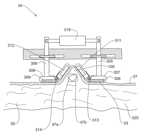
Fig. 7 shows an example of an embodiment 3d of the applicator 3 which delivers
a mechanical manipulation of a skin surface in order to generate a protruding
region of
skin tissue and underlying adipose tissue. The applicator 3d includes a base
element
CA 02642478 2008-08-14
WO 2007/093998 PCT/IL2007/000211
-24-
300, which may be connected to a handle (not sliown). Grooves 301 and 302 are
provided inside the base element 300 in which bars 303 an.d 304, respectively,
can move
laterally. Rods 305 are 306 are attached to the bars 303 and 304,
respectively.
Plates 307 and 308 are connected to the lower end of the rods 305 are 306,
respectively.
The lower surface of these plates is preferably rough or covered with a
suitable high-
friction material 309 in order to eiihance friction and reduce slippage over
the skin.
Ultrasound transducers 311 and 312 are attached to plates 307 and 308
respectively
tlzrough hinges 313 and 314 respectively so as to be free to rotate about the
hinges. The
springs 315 and 316 displace the transducers, 311 and 312, respectively
towards the
] o skin surface 27. At the upper end of the rods 305 and 306, rods 317 and
318,
respectively, are connected. The rods 317 and 318 are driven by an actuator
319.
The embodiment 3d has two ultrasound transducers, arranged symmetrically.
This is by way of example only and a non-symmetrical mechanical manipulator
with
only one transducer or more than two transducers may be used as required in
any
application.
The embodiment 3d of the applicator 3 is used to create a protrusion of a skin
surface as follows. The plates 309 and 310 are applied onto the skin surface
27 at a site
to be treated, as shown in Fig. 7a. The actuator 319 pulls the rods 305 and
306 inwards
together with the plates 307 and 308 and the transducers 311 and 312. As shown
in
Fig. 7b, due to the high coefficient of friction between the layer 309 and the
skin
surface, the body tissue 320 is pushed upwards so as to foim a protrusion 330.
The
springs 313 and 314 are designed so that the moment they exert on the
transducers 311
and 312 is low enough to allow the transducers to rotate about the-hinges 313
and 314,
respectively, so as to allow formation of the protrusion, while at the same
time, ensuring
good coupling of ultrasound energy from the transducers 311 and 312 to the
slcin
su.rface 27. After the protrusion has been foimed, the transducers 311 and 312
radiate
ultrasound energy into the body tissue, to effect reduction of the fat in
focal
volumes 47a and 47b in the subcutaneous adipose tissue 35. The ultrasound
transducers
may be contained inside the plates 307 and 308. In this case, it is desirable
to allow a
degree of freedom of movement to these plates, so as to allow them to conform
to the
protrusion as it forms, either freely, or by forcing them to rotate
simultaneously with the
lateral motion.
CA 02642478 2008-08-14
WO 2007/093998 PCT/IL2007/000211
-25-
The plates 307 and 306 and/or the transducers 311 and 312 may be curved in
any desired shape in order to obtain a protrusion having a desired shape. The
transducers 311 and 312 of the embodiment 3d may be any of those applicable
for the
other embodiments, 3a-3c, that is, planar transducers, fixed focus transducers
or phased
array transducers. If a phased array is used, in a similar way to embodiment
3c (Fig. 6),
a position encoder is preferably added to hinges 313 and 314, and the focal
position
electronically matched to the orientation of the transducers.
The apparatus 4, with the applicator 3b or 3c or 3d, niay be configured to
deliver
ultrasound energy to a region of subcutaneous adipose tissue so as to generate
a
pressure gradient in the region that ruptures cells in the in the region.
Since this effect is
obtained using moderate focusing of the ultrasound radiation in a volume of
subcutaneous adipose tissue to be treated, when the overlying skin surface is
made to
protrude above the surrounding surface, a larger power may be applied with
lower risk
to internal organs and tissues.
Ultrasound energy may be delivered to the skin together with RF energy; as
explained above. Fig. 8 shows schematically an embodiment 3e of the applicator
3 in
which an ultrasound transducer 71 is located between two ~,F electrodes 72 and
73. The
transducer and RF electrodes are supported by an insulating housing 77.
Application of
the applicator 3e to the skin surface 27, applies both the ultrasound
transducer 71 and
the RF electrodes 72 and 73 to the skin surface 27, to obtain good coupling of
the RF
and ultrasound energies to the slcin surface. An electrically conductive
ultrasound
conductive gel may be applied to the skin prior to the treatment. The
ultrasound
transducer is driven tluough cable 74 in the harness 2, while cables 75 and 76
supply the
RF voltage to the electrodes from the RF generator 15 in the control unit 1.
Fig. 9 shows an embodiment 3f of the applicator 3 in which RF electrodes have
been incorporated into the embodiment 3d of Fig. 7. For exaniple, in Fig. 9,
RF
electrodes 341 and 342 are located adjacent to the transducers 311 and 312.
The RF
electrodes are driven through cables 75 and 76, which are included in harness
2 (not
shown). The RF electrodes can be incorporated into the plates 307 and 308 or
on the
transducers 311 aiid 312. In the later embodiment, a thin film of electrically
conducting
material having negligible ultrasound attenuation is preferably applied to
each
transducer face touching the skin 27, and coiulected to the RF power supply 15
in
control unlt 1.
CA 02642478 2008-08-14
WO 2007/093998 PCT/IL2007/000211
-26 -
Fig. 10 shows anotlier embodiment 3g of the applicator 3 in vdhich a pair of
RF
electrodes 81 and 82 has been added to the embodinient 3b of Fig. 5. The RF
electrodes 81 and 82 are located at the sides of the dome 40, so they can
contact the
skin. The RF electrodes 81 and 82 are driven by the RF driver 15 in the
control unit 1
by cables 83 and 84 in the harness 2. The electrodes 81 and 82 and the cables
83 and 84
are electrically insulated froni the housing and from the ultrasound
trailsducers.
The housing 40 is preferably made of insulating material. The high
conductivity contour
through the skin layer 85 is longer and takes less energy than in the planar
embodiment 3e shown Fig. 8, so a higher electric field 86 is created in the
deep adipose
tissue. The electric field heats the minority fluids in the adipose tissue and
generates
strain on the adipose tissue cell membranes, as explained above. Preferably
the
applicators 3f and 3g are designed to malce the regions of maximum electric
field and
maximum ultrasound intensity at least partially overlap within the adipose
tissue, to
maximize the combined effects of the RF and the ultrasound energies. A pair of
RF
electrodes can similarly be added to applicator 3c.
The applicator 3g has RF electrodes parallel to the ultrasound transducers. It
is
also possible according to the invention to locate the RF electrodes at other
positions,
which provide at least partial overlap of the RF electric field and the
ultrasound
radiation within the adipose tissue. Fig. 11 shows schematically another
possible
airangement of the RF electrodes and the ultrasound transducers in side view
(Fig. 11 a),
and in top view (Fig. 11 b). For simplicity, Fig. 11 shows only one pair of RF
electrodes 91 and 92, and a pair of ultrasound transducers 93 and 94.
Preferred RF parameters, for all the embodiments, are: RF frequency between
100 kHz and 50 MHz, more preferred between 500kHz and 5MHz. Applied RF
voltages
are between lOV peak to 1000V peak, more preferred between 30V peak to 300V
peak
for a distance of 10mm between electrodes, and higher voltage for greater
electrode
spacing. The RT electrode spacing may be between 5mm to 50mm and their length
may
be between 5nun to 50nmi.n. Preferably, the ultrasound transducer covers most
of the
area between the electrodes. The ultrasound transducer may be flat with
unifoim phase
wliere the depth of treatment is controlled by the frequency, or a fixed focus
transducer
or a phased array transducer with the capability of scanning the focal volume,
as in
embodiments 3a-3d. Preferably, the RF energy is applied in pulses, typically
between
CA 02642478 2008-08-14
WO 2007/093998 PCT/IL2007/000211
-27-
sec 500 msec, more prefeiTed bet`veen 1 msec to IOOmsec. Preferably the RF and
ultrasound pulses overlap at least pai-tially.
Monitoring the contact between the RF electrodes and the body niay be done by
measuring the voltage across the electrodes and the cuiTent, and calculating
from that
5 the inlpedance between the electrodes. Based on experience with a certain
electrode
structtu=e, a range of impedances can be defined that are sufficient for the
application of
the RF power. As in the previous embodiments, coupling of the ultrasound
energy to the
body can be monitored by measuring the transducer impedance.
The applicator embodiments 3b-3g are independent of any specific physical
model
10 for the destruction of fat cells. However, it is advantageous in all
embodiments to apply
the ultrasound energy in a way that maximizes the selective destruction of fat
cells, as
was done with embodiment 3a, namely, to exploit the unique structure of fat
cells to
effect relative movement between the adipose cell constituents, leading to
strain and
selective heating at the cell boundary, following by damage to the cell
membrane which
cause cell necrosis or apoptosis.
Any of the above einbod'unents may be adapted for delivering infra-red (IR)
energy to the skin surface. Delivering of IR illumination to the - skin
enhances the
aesthetic treatinent, so that fat, cellulites and skin can be treated
simultaneously. The IR
illLUnination can be applied to skin regions not covered by the ultrasound
transducer or
the RF electrodes.