Note: Descriptions are shown in the official language in which they were submitted.
CA 02642590 2008-08-15
, , = ,==
Method and device for generating gas from carbonaceous material
The present invention relates to a method and a device for generating gas
containing CO and
H2 from carbonaceous material. Furthermore, the invention relates to a device
for generating
electrical energy using pyrolysis and gasification of carbonaceous materials
into gas containing
CO and H2 having a gasification reactor, an engine driven with the aid of the
gas containing CO
and H2, and a power generator driven by the engine.
With the background of decreasing resources of fossil fuels, decentralized
power supply on the
basis of waste or biomass from renewable raw materials receives ever more
significance. Heat
is generated in biomass or waste combustion, which may be used for heating
buildings or
water, for example. In gasification, combustion gas which may be used in
engines for power
generation is generated in addition to heat.
Gasification is generally executed in multiple steps: drying/heating for
preparation, pyrolysis,
and gasification, namely the reaction of the pyrolysis products by oxidation
and reduction. The
resulting gas contains, inter alia, hydrogen, carbon monoxide, and methane,
which may be used
as fuel. The composition of the resulting gas is a function of the reaction
gas used and the
temperature at which the gasification occurs. At higher temperatures, the
concentration of
hydrogen and carbon monoxide increases and the concentration of methane
decreases.
The higher the temperature, the lower the probability that the resulting gas
will still contain toxic
or carcinogenic components such as dioxin or tar. This is because at
temperatures of 900 C
and higher, they are cleaved into harmless volatile substances such as carbon
dioxide and
hydrogen. One possibility for providing high temperatures of 900 C and more is
offered by the
use of a plasma burner.
A method and a facility for the gasification of carbonaceous material into a
gas mixture primarily
comprising CO and H2 is known from DE 32 33 774 Al, in which the carbonaceous
material is
introduced in piece form into a shaft furnace up to a predefined filling
height. The shaft furnace
has plasma burners on the floor. In addition to heat energy from the plasma
burners, oxidant is
also supplied in the form of 02, C02, or H20. The carbonaceous material is
therefore subjected
to a high temperature under oxidative conditions. The volatile components are
thus released
CA 02642590 2008-08-15
2
and react with the oxidant. The nonvolatile part, in contrast, is coked.
Oxidant which has not
reacted with the volatile components may react further down in the shaft
furnace with the coke
generated and form additional CO and possibly H20. CO2 and H2O escaping upward
may react
with the carbonaceous material falling downward to form CO and H2. The gas
leaving the shaft
furnace has a temperature of at most 1500 C. The temperature may reach
approximately
2000 C on the surface of the grainy material in the shaft furnace.
One object of the present invention is to provide a method and a device in
which the
carbonaceous material is pretreated.
This object is achieved by a method for the gasification of carbonaceous
material into gas
containing CO and H2 having upstream pyrolysis, in which the pyrolysis of the
carbonaceous
material is performed with the aid of microwave radiation and by heating the
carbonaceous
material, and a gasification of the pyrolysis products is performed
allothermally with the aid of a
water-steam plasma.
By coupling energy into the carbonaceous material via microwaves, the
carbonaceous material
is completely penetrated with little effort and is rapidly heated from the
inside to the outside. In
addition, with carbonaceous material containing moisture, it is sufficiently
dried and the moisture
is converted into water steam, which is then available as an oxidant during
the gasification.
Because the carbonaceous material is heated from the inside to the outside,
combustion is
suppressed and instead the carbonaceous material is pyrolytically cleaved into
volatile carbon
compounds and nonvolatile carbon compounds having shorter carbon chains. The
carbonaceous material may be preheated or heated after or in parallel to the
microwave
radiation by conventional heating means from the outside to the inside. The
time required for
the most complete possible pyrolysis is reduced and the energy balance of the
overall process
is improved as a whole by the heat introduction occurring from the inside to
the outside and the
outside to the inside. The pyrolysis products are used hereafter as educts for
the gasification,
which runs more rapidly and efficiently because of the pyrolysis which has
already been at least
partially performed.
A significant advantage of the method according to the invention is that it
may be used
especially well even in small-dimensioned facilities for decentralized power
supply. This is
CA 02642590 2008-08-15
3
because due to the pretreatment using microwaves, for example, even household
waste or
biomass in the form of garden waste may be used without complex prior
preparation. Namely,
the drying and heating and the pyrolysis are largely or completely achieved by
the microwave
irradiation. A heating unit for supporting the pyrolysis may also be provided
with only a small
space requirement.
Depending on the processing parameters, in particular temperature and reaction
partner,
autothermal or allothermal gasification may be performed. To ensure the most
complete
possible gasification, the gasification is performed here with the aid of
external heat
introduction, specifically by a plasma. This is because temperatures may be
achieved without
problems with the aid of a plasma at which it is ensured that residues of tar
or compounds
hazardous to health are also cleaved and converted into CO and H2 in
particular. A water-steam
plasma is used according to the invention. It comprises 0-, H-, OH-, O2-, H2-,
and H20-radicals,
which react very well with the pyrolysis products and carbonaceous material
which has possibly
not yet been pyrolyzed. In addition, the enthalpy density of water-steam
plasma is very high.
These properties result in an acceleration of the gasification process.
Because additionally the
thermal efficiency of water-steam plasma sources is from 70-90%, the use of
water-steam
plasma is cost-effective in operation. The use of both pure water-steam plasma
and also
plasma made of water steam with additives or gas mixtures with water steam as
a reaction
accelerator are advantageous.
In a preferred embodiment, a pore burner is used for heating during the
pyrolysis. Pore burners
are especially well suitable because they provide a very high power density
and may
additionally be operated using synthesis gas produced according to the present
invention, which
is still hot. This results in an improved overall energy balance of the
method.
In a very especially preferred embodiment, the gasification immediately
follows the pyrolysis.
The pyrolysis products may thus be treated further by gasification before they
cool off, so that
they may be brought to the processing temperature for the gasification in
minimal time. This
improves the overall energy balance of the method. Moreover, in comparison to
typical
methods, because of the use of a water-steam plasma for the gasification and
the especially
efficient pyrolysis by the combination of microwave irradiation and thermal
irradiation, a complex
material stream separation into solid and volatile pyrolysis products may be
dispensed with.
CA 02642590 2008-08-15
4
In a preferred embodiment, the pyrolysis products and/or the carbonaceous
material and/or
gasification products are at least partially subjected more than once to an
external heat
introduction in the form of a water-steam plasma. The efficiency of the
gasification process is
thus increased. Material particles, whether they are pyrolysis products or
possibly not yet
reacted starting products made of carbonaceous material, which were not
completely gasified
during the first passage through a zone having external heat introduction, are
gasified upon a
further passage through such a zone. In addition, they enhance the heat
transfer to newly
supplied material particles, by which the gasification efficiency also
increases. The particles
may be guided via a fan or mechanically in such a way that they are again
subjected to the
external heat introduction. If a plasma source is used to generate the
external heat introduction,
they are preferably suctioned toward the plasma while exploiting a nozzle
effect. They thus
come directly into the hot plasma flame, whereby a strong volume enlargement
of the gaseous
components results. This volume enlargement results in an acceleration in the
direction of
further pyrolysis products and/or carbonaceous material leaving the microwave
irradiation. The
components coming from the plasma flame mix with the components newly coming
from the
microwave irradiation, heat them rapidly, and accelerate the gasification
process.
It has proven to be advantageous to compact the carbonaceous material before
and/or during
and/or after the microwave irradiation. The compaction results in more
efficient energy
introduction by microwave irradiation and/or heat irradiation and is
preferably performed before
the microwave irradiation and/or possibly the heat irradiation. The most
complete possible
pyrolysis of the carbonaceous material by the microwave irradiation is thus
achieved.
In particular, but not only if the carbonaceous material has been compacted,
the pyrolysis
products and/or the carbonaceous material are advantageously comminuted after
the
microwave irradiation. The surface of the material to be gasified is thus
enlarged, which results
in a further acceleration of the gasification process. The overall energy
balance is additionally
improved. This is because, in contrast to the comminutation of the starting
material before the
pyrolysis, for which quite a large amount of energy is required in certain
circumstances, the
solid pyrolysis products, which are largely carbon, may be comminuted with
relatively little effort
and energy.
CA 02642590 2008-08-15
In a further aspect of the present invention, the object is achieved by a
device for the
gasification of carbonaceous material into gas containing CO and H2, which has
at least one
microwave station and one heating unit to at least partially perform the
pyrolysis of the
carbonaceous material, as well as a first reactor having at least one water-
steam plasma burner
5 to perform the gasification. As an advantageous side effect, not only are
the molecular
structures broken, but by the microwave and heat irradiation the carbonaceous
material is dried
and/or heated as needed in the microwave station. The pyrolysis products are
then converted
especially energy efficiently in the water-steam plasma into synthesis gas
having a high
hydrogen component. This is because if water-steam plasma burners are used,
sufficient
oxidant is also provided with the plasma in addition to the heat energy.
In an especially preferred embodiment, the microwave station or the heating
unit is situated in
the process flow direction directly before the first reactor. This not only
increases the energy
balance of the device, but rather also allows an especially compact design of
the device, so that
it is also well suitable for decentralized power supply.
The microwave station is preferably situated in a second reactor for the
purpose of optimized
pyrolysis on one hand and optimized gasification on the other hand.
The microwave station advantageously has a compaction unit. Depending on the
embodiment,
the compaction unit may be connected upstream from the microwave station
and/or the heating
unit, integrated therein, or connected downstream therefrom. Integration in
the microwave
station suggests itself in particular if irradiation using microwaves and/or
heating by radiant heat
and compaction are to be performed simultaneously. The compaction unit in
particular allows a
more compact construction of the microwave station, which may be thermally
insulated with less
effort.
The heating unit is especially preferably implemented as a pore burner. In
addition to the energy
introduction via microwave irradiation, more efficient heat introduction by
heat radiation is thus
ensured, which acts from the outside to the inside on the material to be
pyrolyzed,
supplementing the action of the microwave irradiation from the inside to the
outside. In contrast
to conventional burners, such as gas burners, significantly higher
temperatures may be
achieved using pore bumers, resulting in a heat introduction which is multiple
times higher.
CA 02642590 2008-08-15
6
A mixing unit is advantageously situated in the first reactor. It is used to
mix the content already
present in the first reactor with the content added from the microwave station
and/or the heating
unit. The added content is thus brought more rapidly to gasification
temperature and the
gasification process is accelerated. The mixing unit is preferably implemented
as a rotatable
screen drum which additionally screens out the ashes.
In a preferred embodiment, a comminuting unit is situated in the first reactor
or at the outlet of
the microwave station and/or the heating unit. It is used to comminute the
solid pyrolysis
products and/or the carbonaceous material after the microwave irradiation.
Their surface is thus
enlarged and the gasification is accelerated. The pulverizing unit is
preferably implemented as a
scraping unit which abrades the surface of the pyrolysis products and/or the
carbonaceous
material which exit from the microwave station or heating unit. The scraping
unit delivers the
gasification processing temperature during the scraping procedure by direct
contact on the
freshly scraped point of the abraded material. In this way, the energy
introduction into the
material particle is accelerated. In addition, a cracked surface results due
to the scraping
procedure, because of which further enlargement of the gasification surface
occurs. The
comminuting device is especially preferably situated on the screen drum, so
that the abraded
particles are immediately mixed with the reactor content already present by
the movement of
the screen drum.
In a preferred embodiment, the at least one water-steam plasma burner is
attached to the first
reactor in such a way that its plasma flame does not or only partially extends
up into the reactor
inner chamber, and an additional duct leads from the first reactor to the
plasma flame. The
reactor content is thus sucked toward the plasma flame, which is accelerated
into the reactor by
strong heating and volume enlargement of the gaseous component thus caused. In
the plasma
flame itself, a material component is gasified into CO and H2 in particular,
and the mixing in the
reactor inner chamber is encouraged by the acceleration of the material into
the reactor inner
chamber and the gasification process is thus accelerated. Because gas-particle
mixture is
permanently suctioned out of the reactor inner chamber through the additional
line toward the
plasma flame in a type of nozzle effect, a continuous gasification process is
maintained. The
advantage of this air circulation system is not only that the gasification
process runs significantly
more rapidly and the dwell time of the material is thus shortened. The reactor
chamber may also
be dimensioned significantly smaller, which has the result that the insulation
losses are strongly
CA 02642590 2008-08-15
7
reduced and the overall efficiency increases. The flow of the material may
also be maintained
mechanically or with the aid of a fan or support the nozzle effect.
Furthermore, the object is achieved by a device for generating electrical
energy using pyrolysis
and gasification of carbonaceous materials into gas containing CO and H2
having a gasification
reactor, an engine driven with the aid of the gas containing CO and H2, and a
power generator
driven by the engine, at least one microwave station and one heating unit
being connected
upstream from the gasification reactor, in which the carbonaceous material is
at least partially
pyrolyzed using microwave irradiation and thermal irradiation, and the
gasification reactor has a
water-steam plasma burner as a heat source. By coupling such a device for the
gasification of
carbonaceous material into gas containing CO and H2 to an engine which uses
the generated
gas containing CO and H2 for power generation, without great preparation
effort and energy
efficiently, carbonaceous materials such as household waste, biowaste, garden
waste, pellets,
inter alia or also industrial waste may not only be converted into heat energy
and chemical
energy, which is stored in the gas containing CO and H2, but rather also
directly into electrical
energy.
The heating unit is advantageously implemented as a pore burner.
In an especially preferred embodiment, the microwave station or the heating
unit is situated in
the process flow direction directly before the first reactor.
In a preferred embodiment, a hot gas burner is connected upstream from the
engine and the
engine is implemented as a Stirling engine. In this way, the generated gas may
be used further
immediately without complex cooling, which would be necessary in typical gas
engines, by
which the overall efficiency of the device for generating electrical energy is
increased. In
addition, Stirling engines have the advantage of being relatively low
vibration, so that the noise
load is correspondingly low. This encourages use in particular in smaller
buildings or living units.
The hot gas burner is preferably implemented as a pore burner. This has the
advantage that the
permitted intake temperature of the gas is still so high that interfering
contaminants such as tar
are still in the volatile state. The effort for cleaning the generated gas may
thus be reduced to a
CA 02642590 2008-08-15
8
minimum, which allows an especially compact and energy-efficient construction
of the device for
generating electrical energy.
The present invention is to be explained in greater detail with reference to a
preferred
exemplary embodiment. In the figures:
Figure 1 shows a perspective view of a first embodiment of a device for gas
generation;
Figure 2 shows a horizontal section through the device from Figure 1;
Figure 3 shows a vertical section in the longitudinal direction through the
device
from Figure 1 in a simplified view;
Figure 4 shows a vertical section perpendicular to the longitudinal direction
through
the device from Figure 1 in a simplified view;
Figure 5 shows a schematic detail view of a first embodiment of a scraping
unit;
Figure 6 shows a schematic detail view of an air circulation channel;
Figure 7 schematically shows the material flow of a gasification;
Figures 8a,b show a schematic detail view of a second embodiment of a scraping
unit
from the side and in a top view;
Figure 9 shows a horizontal section through a device as in Figures 1 through 4
having the scraping unit from Figures 8a,b;
Figures 10a,b show a schematic illustration of a special embodiment of the
scraping unit
from Figures 8a,b;
CA 02642590 2008-08-15
9
Figures 11 a,b,c show views of a further embodiment of a device for power
generation in
perspective from the front and the rear and from the side;
Figure 12 shows a section through a further embodiment of a device for gas
generation;
Figure 13 shows a perspective view of a third embodiment of a device for gas
generation;
Figure 14 shows a horizontal section through a device as in Figure 13;
Figure 15 shows a vertical section in the longitudinal direction through the
device
from Figure 13 in a simplified view;
Figure 16 shows a vertical section through the device from Figure 13 at the
height of
the pore furnace for the pyrolysis;
Figure 17 shows a horizontal section through a device as in Figure 13 having
the
scraping unit from Figures 8a,b; and
Figure 18 shows a vertical section perpendicular to the longitudinal direction
through
the device from Figure 10 in a simplified view.
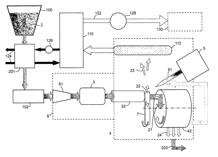
Figure 1 shows a gas generator 1 on a facility 108, which is designed for a
power of
approximately 100 kWe1(net). The starting material may be industrial waste or
household waste
or biomass based on renewable raw materials, such as garden waste, wood chips,
preferably of
a grain size of approximately 6-20 mm, sawdust, pellets, peelings, husks, or
straw. Fossil fuels
may also be gasified in the gas generator.
The carbonaceous material is poured in via the funnel 100. The carbonaceous
material 2 may
already be preheated therein to approximately 60 -80 C using the waste heat of
a gas cooler 10
in the form of a heat exchanger, possibly combined with a gas washer (see also
reference
numeral 201, Figure 7).
CA 02642590 2008-08-15
The carbonaceous material 2 is conveyed further into a secondary reactor 6
with the aid of a
transport screw 102 (see also Figures 2, 3) having drive 104. The carbonaceous
material 2 is
heated to approximately 400-500 C therein. This is predominantly performed via
microwaves
5 which are generated in the microwave generator 31, and a heating device 62,
which uses the
waste heat of the primary reactor 4 in which the gasification occurs, or is
externally supplied
with energy, e.g., as an electrical furnace, or uses a combination of internal
and external
energy. The heating device 62 is attached to the reactor 6 and connected
upstream from the
microwave generator 31.
In addition, the carbonaceous material 2 is guided through a squeezing part 61
enclosed by the
heating device 62. The squeezing part is implemented as conical, the cross-
section tapering in
the conveyance direction. The carbonaceous material 2 is thus compacted
airtight before the
microwave zone 32.
The carbonaceous material 2 is heated from the outside to the inside by the
heating device 62.
The carbonaceous material 2 is penetrated and heated from the inside to the
outside by the
microwave irradiation in the microwave station 3. This combination of supplied
radiant heat and
microwave irradiation results in the best possible heat introduction into the
carbonaceous
material 2.
The carbonaceous material 2 is also dried by the heat introduction. This is
advantageous in
particular for starting materials which are not pretreated further, such as
industrial or household
waste or garden waste, but also in general for biomass made of renewable raw
materials. The
gas generator 1 is therefore insensitive even to larger variations in the
moisture content of the
carbonaceous material 2. The moisture exits from the carbonaceous material 2
as water steam
and is used as an oxidant in the gasification process.
The high heat introduction, in particular into the interior of the
carbonaceous material 2 by the
microwave irradiation, triggers the pyrolysis of the carbonaceous material 2.
During the
pyrolysis, inter alia, the longer-chain molecules of the carbonaceous material
2 are cleaved into
shorter molecules. Volatile and nonvolatile pyrolysis products form, which are
used as educts
for the following gasification. To implement the energy introduction by
microwave irradiation as
CA 02642590 2008-08-15
11
more targeted, the carbonaceous material 2 is guided through a feed pipe 33,
so that all of the
carbonaceous material 2 is guided through the microwave zone 32. In particular
if pellets or
comparable biomaterial are used as the starting material 2, the molecular
structures are simply
broken by the microwave irradiation, because of which the pyrolysis runs more
efficiently. It is
ensured by the airtight compaction in the squeezing part 61 before the
microwave zone 32 that
as little nitrogen as possible enters from the surrounding air, which would
reduce the
combustion value of the generated gas containing CO and H2.
The dimensioning of the microwave generator 31 is a function in particular of
the extension of
the microwave zone 32, the density of the carbonaceous material 2, and the
desired
temperature. The selection of the frequency may be restricted by national
guidelines. For
example, in Germany only the frequencies 24.25GHz, 5.8GHz, 2.45GHz, and, in
special cases,
915MHz are permitted for microwave heating. Instead of one microwave
generator, two, three,
or more may also be used, so that they are able to form either a coherent
microwave zone or
multiple separate microwave zones.
The feed pipe 33 leads into the primary reactor 4, into which a plasma burner
5 also opens and
in which the gasification occurs. The feed pipe 33 leads through a screen drum
42 situated in
the primary reactor 4. The screen drum 42 is mounted so it is rotatable around
its longitudinal
axis and is rotated via the drive 106. The longitudinal axis of the screen
drum 42 is parallel to
the feed pipe 33 in the present example. Screen drum panels 43 are situated on
the interior of
the peripheral wall of the screen drum 42 (see Figure 4 in particular). In
addition, a scraping unit
7, in the form of five blades 71, is attached on the side of the screen drum
42 facing toward the
plasma burner 5, which is carried along with the screen drum 42, guided past
the outlet of the
feed pipe 33 and abrades the surface of the exiting material, i.e., the
nonvolatile pyrolysis
products 21 and possibly the starting material 2 which has not yet been
completely pyrolytically
reacted, because of which small particles 25 arise (see also Figure 5). In
particular the material
which has already been completely pyrolyzed is very friable, so that it may be
crushed easily. In
addition to the surface enlargement by particle formation per se, the
procedure of scraping
results in a cracked and therefore especially large surface, which is
available for the gasification
process, because of which the gasification process may run much more rapidly
and efficiently.
CA 02642590 2008-08-15
12
Figure 12 shows a section through a further embodiment of a gas burner,
specifically
perpendicularly to the feed pipe 33. In this example, the microwave station is
combined with a
pore burner 63 for more intensive pyrolysis, which adjoins the microwave
generator 31 and it is
adapted in its geometry in such a way that it encloses the feed pipe 33.
Because pore burners
are made of ceramic, their geometries may be selected relatively freely. The
present
configuration having the pore burner 63 enclosing the feed pipe 33 is
advantageous, inter alia,
because of the small space requirement. In that the pore burner 63 projects
into the reactor 4 or
alternately is also situated entirely in the reactor 4, it contributes to
warming up the reactor 4, in
particular in the starting phase of the gasification procedure. The pore
burner 63 may be fired
using gas containing CO and H2 generated in the gas generator. Because pore
burners allow
very high gas temperatures, gas generated during the gasification procedure
may be fed thereto
immediately without prior cooling, possibly after dust filtering. In the
example shown in Figure
12, the pore burner 63 achieves six times as high a heat introduction as a
typical gas burner.
Overall, the use of a pore burner in combination with the microwave pyrolysis
improves the total
energy balance of the gas burner while still requiring little space and is
therefore suitable in
particular also for gas generators which are dimensioned for household use.
Opposite to the outlet of the feed pipe 33, the hot gas flow 23 of the plasma
bumer 5 opens into
the primary reactor 4. The abraded particles 25 are therefore subjected
directly to the high gas
flow 23. In addition, the blades 71 of the scraping unit 7 continuously pass
through the hot gas
flow 23, so that they also have the processing temperature of approximately
950 -1050 C and
deliver this temperature to the supplied pyrolysis products 21 and possibly
the carbonaceous
material 2 by the direct contact during abrasion. The particles 25 are
therefore at processing
temperature in a very short time and may be gasified. It is ensured by the
temperature of 950 C
or more in the gasification zone that carbon compounds which are harmful to
health and tar are
also gasified as completely as possible and the content of CO and H2 in the
gasification product
is additionally as high as possible.
Turbulence exists in the hot gas flow, which results in rapid mixing of the
abraded particles with
the remaining reactor content, i.e., with the reaction partners for the
gasification. The
gasification thus occurs more rapidly and intensively, by which the overall
efficiency is
increased. Particles 25 which fall in the reactor inner chamber and are
removed from the hot
gas flow 23 are captured by the screen drum 42 in its panels 43, transported
back to the hot gas
CA 02642590 2008-08-15
13
flow, and shaken therein into the hot gas flow, so that they are again better
available for
gasification. The entire reactor content is continuously circulated, which
further enhances the
gasification.
A further embodiment of a scraping unit is shown in Figures 8a, b in detail
and as a component
of the gas generator in Figure 9. It is a rotating scraping part 72, which is
situated at the outlet of
the feed pipe 33. The scraping part 72 comprises a ceramic disc having windows
75 situated on
its front side. In contrast to the scraping part 7 having blades 71 which is
driven via the screen
drum 42, the rotating scraping part 72 is driven via a shaft 73. Particles 25
are abraded from the
nonvolatile pyrolysis products 21 by the rotational movement. They fly through
the front window
75 out of the feed pipe 73 into the hot gas flow 23 of the plasma burner 5.
Because the volatile
pyrolysis products and the water steam also already arising during drying must
also escape
through the windows 75 out of the feed pipe 33, intensive gasification already
occurs in the area
of the windows 75, which act like small reactor chambers. The overall
efficiency of the gas
generator 1 is increased further.
A special embodiment of a rotating scraping part is shown in Figures 10a, b.
The rotating
scraping part 72' has radially situated windows 74 in addition to the windows
situated on its front
side. It rotates in the feed pipe 33 and is driven via the shaft 73 as above.
The drive 105 of the rotating scraping part 72' essentially comprises a drive
bushing 81 which is
mounted so it is rotatable in a housing (not shown). The rotational movement
is performed in
the present example via a chain wheel 87. However, a gear wheel, a toothed
belt, a wedge belt,
or a similar part may also be used. The shaft 73 is radially guided in the
drive bushing 81, but
may move axially. A tappet star 82 is fastened friction-locked and/or
formfitting at the right end
of the shaft 73 and secured via a screw connection 86. The tappet star 82
engages in circularly
situated grooves in the drive bushing 81. The rotational movement is thus
transmitted from the
drive bushing 81 to the shaft 73. The tappet star 82 may move axially within
the grooves. The
axial movement is limited on the right by a rear path limiter 83, which is
screwed onto the drive
bushing 81. The axial movement is possible to the left against the force of a
spring 84 up to the
end of the grooves in the drive bushing 81.
CA 02642590 2008-08-15
14
The normal operation of the rotating scraping part 72' is shown in Figure 10a.
While it rotates,
the tappet star 82 presses against the rear path limiter 83 and the radial
windows 74 are
covered by the walls of the feed pipe 33. In Figure 10b, the axial pressure
increases on the
rotating scraping part 72' due to an imminent clog of the feed pipe 73. If the
axial force of the
rotating scraping part 72' exceeds the force of the spring 84, the rotating
scraping part 72'
moves to the left in the drawing out of the feed pipe 33 and thus exposes the
radially situated
windows 74. Nonvolatile pyrolysis products 21 may now exit through the windows
74 from the
feed pipe 33 and prevent it from clogging.
The axial position of the tappet star 82 may be defined by a sensor 85 in the
area of the drive
socket 81 and the danger of clogging may thus be counteracted via control of
the input
variables "speed of the scraping device" and "velocity of the material feed".
In addition, the path
measurement of the tappet star 82 allows a determination of the wear state of
the rotating
scraping part 72.
The plasma burner 5 is a water-steam plasma burner in the present example. The
composition
of the water-steam plasma encourages the gasification process very strongly,
because it
comprises the radicals 0, H, OH, 02, H2, and H20 at a mean temperature in the
range of
4000 C and peak values in the core of the plasma flame of approximately 12000
C. The
enthalpy density of water steam is very high and the thermal efficiency of
water steam sources
is 70%-90%. In addition, water steam is easily available. Water-steam plasma
therefore not only
accelerates the gasification process, but rather is also advantageous from
economic aspects.
To reduce the dwell time of the particles 25 in the reactor 4 still further
for the most complete
possible gasification, a primary air circulation channel 41 is provided on the
reactor 4 (see
Figures 3, 6 in particular). The primary air circulation channel 41 connects
the lower area of the
reactor 4 to the connecting piece 52 of the water-steam plasma burner in the
upper area of the
reactor 4. A mixture made of gas 22, 23 located in the reactor 4 and particles
25 from the lower
reactor area is sucked by the energy density of the plasma flame 51 via the
primary air
circulation channel 41. The mixture, at a temperature of approximately 750 C,
arrives directly in
the 4000 C water-steam plasma flame 51 via a type of nozzle effect, because of
which a strong
volume enlargement of the gas results. This volume enlargement results in an
acceleration of
the gas mixture in the direction of reactor 4 with strong turbulence. The
entry cross-section in
CA 02642590 2008-08-15
the reactor 4 is implemented conically as a diffuser 52, to reinforce this
procedure still further.
Moreover, additional secondary air circulation channels 44 are provided, which
conduct
particles 25 from the upper inner chamber of the reactor 4 into the diffuser
52. The nozzle effect
is also exploited again here. With the aid of the secondary air circulation
channels 44, in
5 addition to the action of the primary air circulation channel 41, better
mixing of the reactor
content is achieved in the upper reactor chamber. In addition, the
gasification runs very
intensively because of the especially high temperatures and high radical
density in the plasma
flame 51 and its immediate surroundings.
10 Notwithstanding the exploitation of the nozzle effect, this air circulation
principle may also be
achieved mechanically or with the aid of fans, or these measures may be
combined with the
nozzle effect. One skilled in the art will decide this as a function of the
geometry of the device,
the operating parameters of the plasma source 5 or other external heat
introduction sources.
15 In the reactor 4, the mixture made of gas and particles exiting from the
diffuser 52 is incident on
the scraping unit 7 and the surface of the supplied pyrolysis products 21,
possibly also the
carbonaceous material 2, and heats them to the processing temperature. The
mixture
subsequently flows into the lateral upper area of the screen drum 42 and mixes
with the
material continuously conveyed upward by the screen drum. Not only is a
continuous
gasification process thus maintained. The gasification process also runs more
rapidly due to this
air circulation system.
All of these measures result in a very strongly shortened dwell time of the
material to be
gasified. The primary reactor 4 in particular may thus be dimensioned
significantly smaller,
which has the result that the insulation losses are strongly reduced and the
overall efficiency
may be significantly increased. The overall size of the gas generator may be
decreased so
strongly that in addition to facilities in the output range of approximately
100 kWe, (net) or more,
small facilities for the residential field in the output range of
approximately 24 kWe1(net) are
possible (see below, Figures 11a-c).
The ash 24 arising during the gasification is screened out by the screen drum
42 and falls into
the lowermost area of the primary reactor 4 (see, inter alia, Figure 4). An
ash outlet 114 is
located there, through which the ashes 24 are removed (reference numeral 203
in Figure 7).
CA 02642590 2008-08-15
16
The remaining gasification products 23 are drawn off via the lower reactor
area using a slight
partial vacuum with the aid of a fan 128 from the reactor inner chamber to a
filter unit 112. This
advantageously comprises ceramic filter cartridges 113, which may be
integrated in the reactor
housing. The ceramic filter cartridges 113 are used as a dust filter and have
the advantage that
the generated gas may be filtered without prior cooling, i.e., while still at
approximately 700 -
800 C.
The filter unit 112 and the reactor 4 share an external wall in the present
example (see Figure
4). This has the special advantage that on one hand the reactor 4 is
especially well thermally
insulated on this side and on the other hand the filter unit 112 is preheated
by the reactor waste
heat to operating temperature. In addition, the filter unit 112 and the
reactor 4 share the ash
outlet 114, which simplifies the cleaning of the filter unit 112.
After the filtering, the generated hot gas may be fed directly to an engine
which may be
operated using hot gas for power generation or also to a pore burner. In the
present example,
the hot gas is guided via a line 122 to a further station 120, which has the
function of a gas-
water heat exchanger and/or a washer. The hot gas may thus be cooled to below
50 C and
cleaned. In addition, the heat may be used in that the heated coolant water
which is supplied via
the inlet 116 and removed via the outlet 118 is fed with the aid of a pump 126
into the building
services systems or relayed to an external heat exchanger. The heat may also
be used for
preheating the carbonaceous material 2. The cooled clean gas is drawn off with
the aid of a fan
128 from the system via a partial vacuum and discharged into an external gas
store or a block
heating power plant for further use.
A further embodiment of a gas generator is shown in Figures 11 a-c. This gas
generator is
designed for a power of approximately 2-4 kWei or 8-16 kWthem, and is
therefore suitable for use
in the residential field. Because the internal construction of this gas
generator does not
significantly differ from the gas generator 1 already explained, an internal
view is dispensed with
and only the deviating components are discussed, to which the gas generator in
this example is
connected.
A household facility 10 for generating heat and electrical energy is shown in
Figures 11 a-c. The
household facility 10 is a complete module which essentially comprises a gas
generator and an
CA 02642590 2008-08-15
17
engine connected thereto as a generator drive. The household facility
generates gas containing
CO and H2 from carbonaceous materials as previously described via a pyrolysis
with the aid of
the microwave generator 31 and a heating unit (not visible here) and
gasification via
subsequent external heat introduction, here using a water-steam plasma source.
This gas is
used for driving a Stirling engine 131, which drives a generator 132, by which
power is
generated. The waste heat is used for heating residential buildings and for
generating hot water.
The carbonaceous materials are supplied through the connecting pieces 99 with
the aid of fans
or screws, for example, and reach the double-walled funnel 101 here. After
pyrolysis using
microwave and thermal irradiation and water-steam plasma gasification as
previously
described, the gas containing CO and H2 exits at a temperature of greater than
400 C from the
filter unit 112 made of ceramic filter cartridges and is guided through the
gas pipe 122 into the
hot gas burner 143, in the form of a pore burner here. It is combusted therein
with the
combustion air, which is suctioned via an inlet nozzle 140 by a fan 141 for
noise reduction, in
the hot gas burner 143. The combustion intake air is previously conducted
through the ash
compartment 204, implemented as double-walled here, because of which the air
heats up and
the ash cools down. The risk of fire upon ash disposal is thus minimized. The
combustion intake
air is guided from the ash compartment 204 via the line 142 to the hot gas
burner 143.
The heat energy (approximately 1050 -1100 C) generated in the hot gas burner
143 is used for
driving the Stirling engine 131. This drives the generator 132, so that power
is generated. The
energy to be dissipated which results from the Stirling process is introduced
via a coolant water
outlet 135 into a water/water heat exchanger 134. The cooled-down water (AT
approximately
40-50 C) is introduced back into the Stirling engine 131 via the coolant water
inlet 136. The hot
exhaust gases (approximately 600-700 C) from the hot gas burner 143 are fed
via a line 137 to
a gas/water heat exchanger 133. After flowing through the gas/water heat
exchanger 133, the
exhaust gases reach the funnel 101 via a line 138 and heat the carbonaceous
materials
introduced therein through the connecting pieces 99. The exhaust gases reach
the flue of the
building at a temperature of approximately 50 C via a pipe connection 139. The
waste heat from
the heat exchangers 133, 134 is fed via a coolant water inlet 116 and a
coolant water outlet 118
into the building's heating installation and the hot water preparation.
CA 02642590 2008-08-15
18
The advantages of the domestic facility 10 may be seen in that carbonaceous
materials such as
pellets, green wastes, household waste, etc., may be used for the power supply
of residential
buildings. In addition to the necessary room heating and hot water
preparation, electrical current
is generated, which is fed into the power network in the idle times and
credited. This decreases
the energy cost of the individual households and contributes to
decentralization of the power
market. Devices from the size of floor heaters up to multifamily houses may be
implemented by
the compact overall size of the gas generator. No tars may precipitate due to
the combustion of
the gas at temperatures above 500 C, so that the gas cleaning may be
restricted to the dust
filter 112 using ceramic filter cartridges.
The third device for gas generation shown in Figure 13 differs from the first
device shown in
Figure 1 in particular in regard to the design of the pyrolysis station. While
in the first device the
material to be pyrolyzed is first heated with the aid of the heating unit from
the outside to the
inside after the compaction before it is irradiated using microwaves, to also
heat it from the
inside to the outside (see also Figures 2 and 3), in the third device, the
material to be pyrolyzed
is first irradiated using microwaves of the microwave generator 31 to achieve
the pyrolysis
temperature in the interior, and subsequently guided through a heating unit,
in this example a
pore furnace 63, to also bring the material to pyrolysis temperature from the
outside to the
inside.
A vertical section through the device from Figure 13 at the height of the pore
burner 63 is shown
in Figure 16. In contrast to the example shown in Figure 12, in this example
the microwave
station is combined with three pore burners 63 for more intensive pyrolysis,
which adjoin the
microwave generator 31 and are situated around the feed pipe 33 in the area of
its lower
periphery, so that the radiant heat 66 radiates on the feed pipe 33. The pore
burner 63 may be
fired using synthesis gas containing CO and H2 generated in the gas generator,
which is fed via
the synthesis gas connections 64. The synthesis gas is combusted together with
air and/or
oxygen in the pore area of the pore burners 63 while generating heat energy.
The exhaust
gases arising exit through the exhaust gas outlet 65 and may be used for
preheating other
components. The pore area is generally formed by ceramic foam or another
structure resistant
to high temperatures. Their very high power density of approximately 1000
kW/mZ is a special
advantage of pore burners. In particular, high temperatures of up to
approximately 1400 C may
be achieved. Further advantages are high heating rates and good ability to
regulate the furnace
CA 02642590 2008-08-15
19
temperature. Because pore burners allow very high gas temperatures, gas
generated during the
gasification procedure may be fed immediately thereto without prior cooling,
possibly after dust
filtering. In the example shown in Figure 16, the pore burner 63 achieved six
times as high a
heat introduction as a typical gas burner. Overall, the use of a pore burner
in combination with
microwave pyrolysis improves the overall energy balance of the gas burner
while nonetheless
requiring little space and is therefore also suitable in particular for gas
generators which are
dimensioned for household use.
Furthermore, several differences from the first device exist in the
gasification reactor 4 of the
third device (see Figure 14): the feed pipe 33 for feeding the pyrolyzed
material and the plasma
burner 5 are situated in relation to one another in such a way that the hot
gas flow generated by
the plasma flame 51 is incident not only laterally, but rather also frontally
on the.scraping unit 72
(see also Figures 8a, b), to heat up the scraping unit 72 still better. During
the scraping, the
scraping unit 72 transfers its temperature to the material to be comminuted.
Due to the frontal
orientation of the hot gas flow 23 on the scraping unit 72, in addition, the
hot gas flow also better
directly heats the material to be comminued to processing temperature for the
gasification in the
front windows 75 of the scraping unit 72.
The heating of the pyrolysis products immediately after the pyrolysis, when
they are at a very
high temperature because of the pore burner, has the result that gasification
already begins to
occur in the feed pipe 33 toward its outlet on the gasification reactor side.
Gasification already
partially also occurs in the front windows 75 of the scraping unit 72.
The advantage of this smooth transition from pyrolysis to gasification is that
the solid pyrolysis
products are gasified very efficiently and only little ash remains. Therefore,
in the second device
shown here, the drum 45 is also not implemented as a screen drum, but rather
only as a drum
45 having drum panels 43 (see Figure 15), to introduce particles 25 which have
not yet been
gasified back into the hot gas flow. The little ash 24 may exit via the front
faces of the drum 45
and be removed via the ash outlet 114. The drum 45, which is not implemented
as a screen
drum, has the additional advantage of more efficient thermal insulation of the
inner chamber of
the gasification reactor 4.
CA 02642590 2008-08-15
The plasma flame 51 is situated in the second device in a diffuser 52 provided
with openings 53
(see Figure 14). In the water-steam plasma flame 51, the volatile and solid
pyrolysis products
come together with the radicals generated therein, with which they react to
form CO and H2.
Moreover, they are heated very strongly very rapidly in the plasma, so that a
sudden volume
5 expansion occurs, which results in a local partial vacuum. Further pyrolysis
products are sucked
into the water-steam plasma flame 51 through the openings 53 via this local
partial vacuum, so
that a continuous hot gas flow is maintained.
Due to the shortening of the feed pipe 33 and the projection of the plasma
burner 5 into the
10 gasification reactor 4, the space required is reduced further for the third
device in comparison to
the first device.
It is to be noted that the third device for gas generation from Figures 13
through 16 may also be
implemented having the scraping unit 72 as in Figures 8a, b or also having
blades 71 as in
15 Figure 4 or another scraping unit. It is also possible to provide the third
device entirely without a
comminuting unit, as shown in Figures 17 and 18. Depending on the selection of
the
carbonaceous material, due to the especially efficient pyrolysis presented
here, the solid
pyrolysis products may be so friable that they do not require additional
comminuting. Because
the hot gas flow 23 is additionally directly incident on the pyrolysis
products when they enter into
20 the reactor 4, they are brought in a minimal time to a sufficiently high
temperature for low-
residue gasification.
Furthermore, it is to be noted that the third device for gas generation was
also described in a
device for power generation as with reference to Figures 11 a-c, for example.
CA 02642590 2008-08-15
21
List of reference numerals
1 gas generator
household facility
5 2 carbonaceous material
21 nonvolatile pyrolysis products
22 volatile pyrolysis products
23 hot gas flow
24 ash
10 25 abraded particles
3 microwave station
31 microwave generator
32 microwave zone
33 feed pipe
4 primary reactor
41 primary air circulation channel
42 screen drum
43 screen drum panel
44 secondary air circulation channel
45 drum
5 plasma burner
51 plasma flame
52 diffuser
53 opening
64 gas connection
65 exhaust gas outlet
66 radiant heat
6 secondary reactor
61 squeezing part
62 heater
63 pore burner
7 scraping unit
71 blade
CA 02642590 2008-08-15
22
72, 72' rotating scraping part
74 radially situated window
75 frontally situated window
81 drive bushing
82 tappet star
83 rear path limiter
84 spring
85 sensor
86 screw connection
87 chain wheel
99 connecting piece
100 funnel
101 funnel (with surrounding exhaust gas flow)
102 transport screw
104 drive transport screw
105 drive rotating scraping device
106 drive screen drum
108 support
110 heat exchanger/washer
112 filter unit
113 ceramic filter cartridge
114 ash outlet
116 coolant water inlet
118 coolant water outlet
120 clean gas outlet
122 gas line
124 feed into building services system/external heat exchanger
126 pump
128 fan
130 external gas store/block heating power plant/engine
131 Stirling engine
132 generator
133 gas/water heat exchanger
CA 02642590 2008-08-15
23
134 water/water heat exchanger
135 coolant water outlet
136 coolant water inlet
137 line
138 line
139 pipe connection
140 intake nozzle
141 fan
142 combustion air line
143 hot gas burner
201 preheating
203 ash disposal
204 ash compartment