Note: Descriptions are shown in the official language in which they were submitted.
= CA 02643110 2013-07-19
54106-259
- 1 -
Device for short-circuiting of power semiconductor modules
FIELD OF INVENTION
The invention relates to an apparatus having power
semiconductor modules which are connected to one another via
connection means, forming a series circuit, with each power
semiconductor module having an associated short-circuiting
device for short-circuiting of the respective power
semiconductor module.
BACKGROUND OF INVENTION
An apparatus such as this is already known from DE 103 23 220
Al, which describes a converter which comprises a bridge
circuit with bridge arms. In this case, each bridge arm has a
series circuit formed from power semiconductor modules, which
are connected to one another via connection means. The two-pole
power semiconductor modules have a different terminal voltage
in different controllable switching states. Each power
semiconductor module also comprises an internal voltage
intermediate circuit with an energy store. The power
semiconductor modules are not connected to one another via a
pressure contact of the respective power semiconductors. A
short-circuit within the power semiconductor module can
therefore lead to the occurrence of arcs, resulting in
explosion gases or the like. In order to draw the driving
voltage from the arc, the faulty power semiconductor module is
short-circuited and is in this way bridged in the series
circuit. For short-circuiting, a short-circuiting device is
connected in parallel on the power semiconductor module, and
comprises a sacrificial component composed of semiconductors.
CA 02643110 2013-07-19
54106-259
- 2 -
The sacrificial component breaks down when short-circuited in
the event of a fault, being destroyed in the process. The
already known short-circuiting apparatus is of complex design,
however, and is costly.
DE 199 55 682 A2 discloses a current-limiting device for high
voltage, which has an explosive charge in order to open a main
current branch. Once the main current branch has been opened,
the current is commutated onto a secondary branch, which has a
capacitor. The current flowing through the device is limited as
a function of the impedance of the capacitor.
DE 102 54 497 B3 discloses a short-circuiting device having a
light receiver whose optical output signal is used to activate
a photochemical reaction of a reaction mixture. For this
purpose, the light from a fault arc that has been struck is
passed via optical waveguides to a reaction chamber, which is
filled with the reaction mixture. The photochemical triggering
of the reaction mixture leads to an explosive pressure increase
in the chamber, as a result of which a short-circuiting device
is in turn mechanically operated.
Furthermore, DE 225 540 Al discloses a drive for electrical
switches with explosive triggering.
SUMMARY OF INVENTION
An object of the invention is to provide an apparatus of the
type mentioned initially which has a reliable short-circuiting
device, which at the same time is cost-effective.
The invention achieves this object in that the short-circuiting
device is a pyrotechnic/mechanical element which has an
CA 02643110 2013-07-19
54106-259
- 2a -
explosive charge and an initiation means which can be moved by
the explosive charge.
For the purposes of the invention, a cost-effective
pyrotechnic/mechanical element is used to bridge a power
semiconductor module. Pyrotechnic/mechanical elements such as
these have, for example, been known in the form of belt
tighteners or for opening
CA 02643110 2008-08-21
PCT/DE2006/000344 - 3 -
2006P03753WOUS
armoured vehicles. In addition to a quick reaction time, they
are extremely highly reliable. Furthermore, only a limited
amount of energy is required to initiate the explosive charge
although the resultant pressure wave results in high forces
being introduced into the initiation means, which are mounted
such that they can move in the remaining components of the
pyrotechnic/mechanical element. The initiation means are
expediently mounted such that they can move only over a
predetermined movement distance when initiated. This makes it
possible to even further avoid damage to sensitive components
in the apparatus according to the invention. According to the
invention, this allows reliable switching even over long lives.
The use of the pyrotechnic/mechanical element therefore allows
apparatuses according to the invention to be designed, such as
converters, which are of modular design, with the individual
modules being connected via connection means. Complex pressure
contact with the individual power semiconductors has therefore
become superfluous. The converters can thus be produced cost-
effectively. In the event of a short-circuit, the faulty power
semiconductor module can be reliably short-circuited by means
of the pyrotechnic/mechanical element such that damage to the
remaining components in the converter or to people in the
vicinity of the converter is, according to the invention,
reliably avoided. Pyrotechnic initiations have admittedly
already become known in the field of power distribution.
However, the invention has identified the fact that explosive
charges can also be used in conjunction with sensitive power
semiconductors. To this end, for the purposes of the invention,
each pyrotechnic/mechanical element is arranged with respect to
the power semiconductor modules, and is equipped in such a way,
that it is reliably possible to preclude said damage resulting
from the explosion that then takes place on initiation.
CA 02643110 2008-08-21
PCT/DE2006/000344 - 4 -
2006P03753W0US
Each power semiconductor module expediently has at least one
associated energy store, for example at least one capacitor.
According to one advantageous refinement of the invention, the
pyrotechnic/mechanical element has a housing in which the
explosive charge is arranged. By way of example, the housing
provides protection for the power semiconductor modules. The
housing is expediently made thick enough to avoid bursting of
the housing or of other parts of the pyrotechnic/mechanical
element in the event of an explosion.
According to one expedient further development of the invention
in this context, the housing is gas-tight when initiated, so as
to avoid the occurrence of explosive gases. This can virtually
completely avoid the risk of damage to the power semiconductor
modules by the explosive charge in the event of an explosion.
The pyrotechnic/mechanical element is designed such that all
that occurs is mechanical movement of the initiation means on
initiation. According to this further development, no further
side effects occur within the scope of the invention. In this
context, pyrotechnic/mechanical elements have become known
which heat up only to about 60 Celsius after the explosive
charge has been triggered at room temperature, and without
releasing external explosive gases.
The pyrotechnic/mechanical element advantageously has at least
two drive connections for initiation of the explosive charge.
The provision of two drive connections allows the explosive
charge to be driven redundantly, thus even further improving
the initiation reliability.
CA 02643110 2008-08-21
PCT/DE2006/000344 - 5 -
2006P03753W0US
The pyrotechnic/mechanical element is advantageously composed
of at least one electrically conductive material and, in an
initiation position, connects the series circuit to a bypass
branch such that a power semiconductor module which is
associated with the pyrotechnic/mechanical element is bridged.
According to this further development of the invention, current
flows via the pyrotechnic/mechanical element itself in the
event of a fault. In other words, the pyrotechnic/mechanical
element is part of the bypass branch for the faulty power
semiconductor module.
The pyrotechnic/mechanical element can expediently be triggered
electrically. Electrical triggering such as this is both
reliable and cost-effective.
According to one further development in this context, the
pyrotechnic/mechanical element has at least one measurement
sensor for detection of an electrical signal to be monitored of
the associated power semiconductor module, with each
measurement sensor being connected to an initiation unit which
is designed for electrical triggering of the explosive charge.
By way of example, the initiation unit is equipped with
expedient logic which is designed to check the signal to be
monitored, using internal logic. The signal to be monitored is,
for example, proportional to a voltage which, for example, is
dropped across a capacitor in the power semiconductor module to
be monitored, to a current or to a rate of change of said
voltage or of said current. If a voltage is monitored, the
measurement sensor is, for example, a calibrated voltage
converter which produces a voltage signal that is dependent on
the voltage and is sampled by the initiation unit in order to
obtain sample values, with the sample values being converted to
digital voltage measured values by an analog/digital
CA 02643110 2008-08-21
PCT/DE2006/000344 - 6 -
2006P03753W0US
converter. The digital voltage measured values may, for
example, be compared with a configured threshold value. In
contrast to this, however, analog evaluation of the measurement
sensor signals is possible. Initiation processes such as these
are, however, very well known to a person skilled in the art,
so that there is no need to describe them in any more detail at
this point.
The movable initiation means can advantageously be moved by the
explosive charge into the housing. Pyrotechnic/mechanical
elements such as these have become commercially available under
the name "pin-puller". According to this advantageous further
development, the pyrotechnic/mechanical element acts like an
interlock, with the interlock being released after initiation
of the explosive charge and, for example, with a prestressed
spring being released, which closes an associated switch or
contact.
It is, of course, also possible to move the movable initiation
means out of the housing, such that the switching movement of
the pyrotechnic/mechanical element can be produced directly.
The switching movement is then introduced into expedient
kinematics such that contacts to bridge the respectively
associated power semiconductor module are closed.
Pyrotechnic/mechanical elements have become known, for example,
by the name pyrotechnic actuators. The movement distance of the
movement is advantageously also designed to be limited in this
case, thus avoiding the risk of damage to further components in
the apparatus.
The apparatus according to the invention expediently has an
auxiliary contact which can be used to check whether the
pyrotechnic/mechanical element has been initiated after
triggering.
CA 02643110 2013-07-19
,
54106-259
- 6a -
In accordance with this invention there is provided an
apparatus having power semiconductor modules which are
connected to one another via connection means, forming a series
circuit, with each power semiconductor module having at least
one associated energy store and an associated short-circuiting
device for short-circuiting of the respective power
semiconductor module, wherein the short-circuiting device is a
pyrotechnic/mechanical element which has an explosive charge
and an initiation means which can be moved by the explosive
charge, and wherein the pyrotechnic/mechanical element has a
housing in which the explosive charge is arranged, and wherein
the pyrotechnic/mechanical element is composed of an
electrically conductive material and, in an initiation
position, connects the series circuit to a bypass branch such
that a power semiconductor module which is associated with the
pyrotechnic/mechanical element is short-circuited, and wherein
the pyrotechnic/mechanical element can be triggered
electrically.
CA 02643110 2013-07-19
54106-259
- 7 -
BRIEF DESCRIPTION OF THE DRAWINGS
Further expedient refinements and advantages of the invention
are the subject matter of the following description of
= exemplary embodiments of the invention with reference to the
figures of the drawing, in which the same reference symbols
refer to components having the same effect, and in which:
Figure 1 shows a pyrotechnic/mechanical element
having an initiation unit, illustrated schematically,
= Figure 2 shows an exemplary embodiment of a
pyrotechnic/mechanical element, and
Figure 3 shows a further exemplary embodiment as
shown in Figure 2.
DETAILED DESCRIPTION OF THE INVENTION
Figure 1 shows one exemplary embodiment of a
pyrotechnic/mechanical element 1, which has a gas-tight housing
in which an explosive charge is arranged. The initiation of the
explosive charge leads to movement of an initiation means,
which cannot be seen in Figure 1 but whose drive movement is
introduced into expedient kinematics 2 in order to close a
switch or a short-circuiting device 3. When the switch 3 is
closed, this results in bridging of a power semiconductor
module which is arranged in a series circuit of power
semiconductor modules. Said series circuit is part of a
converter.
CA 02643110 2013-07-19
54106-259
- 7a -
A drive unit 4 is provided in order to initiate the
pyrotechnic/mechanical element and is connected via connection
lines 5 to measurement sensors, which are not illustrated in
the drawing in Figure 1.
CA 02643110 2008-08-21
PCT/DE2006/000344 - 8 -
2006P03753W0US
In the exemplary embodiment shown in Figure 1, the drive unit
is used to monitor a power semiconductor module 1 which has an
energy store, for example in the form of a capacitor, which is
not illustrated in the figures but is associated with said
power semiconductor module 1. The drive unit 4 uses the
connection lines 5 to monitor the voltage dropped across the
capacitor. In the event of a short circuit, the voltage rapidly
collapses. If this gradient exceeds a specific predetermined
threshold, the drive unit initiates an explosion of the
explosive charge in the pyrotechnic/mechanical element 1, thus
leading to closing of the switch 3. This results in the faulty
power semiconductor module being bridged, therefore allowing
current flow via the other power semiconductor modules 1 which
are connected in series with the faulty power semiconductor
module 1.
Furthermore, it is possible to detect whether a specific
voltage threshold has been exceeded, and it is possible to
deduce a fault within the power semiconductor module 1 from
this. In this case, this power semiconductor module is short-
circuited immediately, for example in order to avoid a further
increase in the capacitor voltage which is dropped across a
capacitor in the power semiconductor module, and therefore a
greater energy content in said capacitor.
Electrical power supply electronics 6 are provided in order to
supply power to the drive unit, and are connected to an
electrical power supply via connecting lines 7.
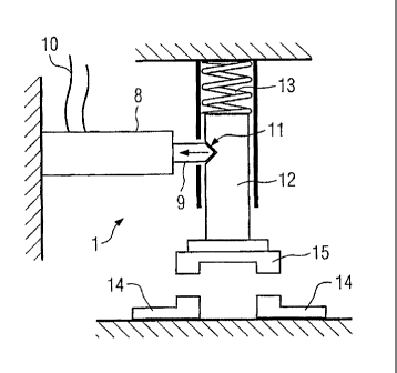
Figure 2 shows one exemplary embodiment of the
pyrotechnic/mechanical element 1, which has a housing 8, a
switching pin 9 and a drive line 10. The explosion of the
explosive charge in the interior of the housing 8 results in
CA 02643110 2008-08-21
PCT/DE2006/000344 - 9 -
2006P03753W0US
the switching pin 9 being moved into the housing 8. In this
case, the housing 8 is designed to be gas-tight, by the use of
expedient seals, thus avoiding the occurrence of explosive
gases outside the housing, despite the explosion of the
explosive charge. Damage to the sensitive power semiconductor
components is therefore avoided for the purposes of this
further development of the invention.
In the illustrated exemplary embodiment, the switching pin 9 is
used for interlocking. For this reason, the tip of the
switching pin 9 is shown as being conical, with the conical tip
engaging in a complementary recess 11 in a switching rod 12.
During normal operation, a compression spring 13 is prestressed
by the interlocked switching rod 12. After initiation of the
pyrotechnic/mechanical element 1, the interlocking of the
compression spring 13 is cancelled, and the compression spring
13 is released, thus leading to the contact link 15 bridging
the contacts 14. When the contact link 15 makes contact with
the contacts 14, the associated faulty power semiconductor
component is bridged.
Figure 3 shows a further exemplary embodiment of the
pyrotechnic/mechanical element 1 which, in the illustrated
exemplary embodiment, is manufactured completely from a
conductive material, for example a suitable metal.
Corresponding to the exemplary embodiment shown in Figure 2,
the pyrotechnic element 1 illustrated in Figure 3 has a housing
8 as well as a switching pin 9, in which case, in contrast to
the exemplary embodiment shown in Figure 2, the switching pin 9
is designed such that it can be moved out of the housing 8 in
the event of explosion of the explosive charge. In the
illustrated operating position, the switching pin 9 is
disconnected from the mating contact 14. However, in the moved-
out position, a contact is made between the switching pin 9 and
the mating contact 14, thus allowing
CA 02643110 2008-08-21
PCT/DE2006/000344 - 10 -
2006P03753W0US
a current to flow via the pyrotechnic/mechanical element 1,
bridging the faulty power semiconductor module.