Note: Descriptions are shown in the official language in which they were submitted.
CA 02643527 2008-10-14
WO 2008/140439 PCT/US2006/014507
-1-
Medical Closure Clip Svstem and Method
Technical Field
The present iryvention relates generally to medical (including dental,
veterinary,
etc.) closure and wound fiuld management devices, and in particular to a
screen
closure member for closing tissue separations, such as incisions and wounds,
which
closure member is optionally bloabsorbable. The closure member can be
assembled
with different components chosen for their functional and material
compatibility
characteristics.
Bac qround_Art
In the medical field, which is broadly defined to include dentistry,
veterinary
medicine, etc., cutaneous incisions are commonly performed in surgery to
provide
access to underlying tissue, organs, joints, skeletal structure, etc. Incision
and
closure techniques are an impoltant part of surgery in general. They tend to
occupy
surgical teams and other resources for significant portions of many surgical
procedures.
Surgeons generally strive to minimize the traumatic and scarring effects of
surgery on their patients by both minimizing the incisions, and by employing a
variety
of closure techniques which tend to reduce. postoperative sweiling, bleeding,
seroma,
infection and other undesirable postoperative side effects. For example, the
fields of
endoscopic-assisted surgery, microscopic surgery, and computerrenhanced
instrumentation (e.g., the DaVinci System available from Intuitive Surgical,
Inc. of
Sunnyvale, Calif.) are generally concemed with minimally invasive surgery
("MIS")
procedures and techniques, which have proven to be increasingly popular. Such
popularity is at least partly due not only to the minimally-sized scars left
by such
techniques, but also to the minimal trauma to the fascia and muscle layers and
the
3o correspondingly faster recoveries this allows. However, surgeons must
balance such
considerations with providing adequate access to perform various surgical
procedures. A typical surgical procedure involves a cutting or dissecting
phase and a
closing phase. In recent years, considerable progress has been made in
minimizing
CA 02643527 2008-10-14
WO 2008/140439 PCT/Y]S2006l014507
~ -2-
surgical cutting, dissecting and shaping. Surgical closing techniques involve
sutures,
clips, staples and adhesives. However, suturing can be time-consuming and
tedious.
Moreover, the tissue structures to be joined may not be amenable to other
closure
techniques. MIS often restricts access to the separated tissue structures,
thus
6 making it more difficult to approximate and dose same,
In contrast to MIS, some surgical procedures, by their nature, must include
long Incisions. Examples include cutaneous excisional procedures such as
"1'ifts" and
reduction procedures, flap procedures for closure of defBcts, and many
bariatric
procedures. Suturing in these extensive defects can be time-consuming and
tedious.
The "first intention" (primary intentton healing) in surgery Is to "close" the
incision. For load-bearing tissues, such as bone, fascia, and muscle, this
requires
substantial materiai, be it suture material, staples, or plates and screws.
For the
wound to be "closed," the epithelial layer must seal. To accomplish this, the
"load
beaNng" areas of the cutaneous and subcutaneous layers (i.e., the deep dermal
elastic layer and the superficial fascia or fibrous layers of the adipose
tissue,
respectively) must also at least be held in approximation. Important
considerations
include controlling infection and bleeding, reducing scarring, eliminaiing the
potential
of hematoma, seroma, and "dead-space" formation and managing pain. Dead-space
problems are more apt to occur in the subcutaneous closure. Relatively shallow
incisions can normally be closed with surface-applied closure-techniques, such
as
sutures, staples, glues, and adhesive tape strips. However, deeper incisions
may
well require not only skin surface closure, but also time-consuming placement
of
multiple layers of sutures in the load-bearing planes. Absorbable sutures are
commonly used for this purpose and comprise an important class of surgical
sutures.
Depending on various factors, absorbable sutures typically dissolve over a
period of
a few days to a few months. Commercially available examples include
Monocryl® monofilament absorbable synthetic sutures cornprising a
polig{ecaprone and PDS® (polydrioxanone) and VicryI® (polyglactin)
sutures, all available from Ethicon, Inc., of Somerville, N.J.
Surgical mesh is commonly used to span or reinforce load-bearing planes or
defects in them. When coupled with sutures or fasteners, surgical mesh
represents
another important class of surgical closure devices. Applications include
reconstruction, herriia repair, and organ repair. In such procedures, surgical
mesh
CA 02643527 2008-10-14
WO 200Ei/140439 PCT/US2006/014507
fabric prostheses are inserted Into patients through either open surgery or
endoscopic (MIS) procedures. Knitted surgical mesh for hemia repair is
disclosed fn
the Agarwal et al. U.S. Pat. No. 6,287,316, which is assigned to Ethicon, Inc.
Another Ethicon, Inc. patent. Duncan U_S. Pat. No. 4,548,202, discioses mesh
tissue
6 fasteners including various fastehing members with spaced-apart legs for
passing
through tissue portions. Another closure procedure involves the placement of
pins or
rods through skin edge or bone followed by the placement of an external clamp
or
fixator device spanning the wound and freguentiy incorporating a worm-screw
apparatus capable of progressive tightening over time to effect closure,
stabilization
1o or distraction.
Fluid management represents another important aspect of both open and
minimally invasive surgery. Postoperative fluid drainage can be accomplished
with
various combinations of tubes, sponges, and porous materials adapted for
gathering
and draining bodily fluids. The prfor art includes technologies and
methodologies for
15 assisting drainage. For example, the Zamierowski U.S. Pat. No. 4,969,880;
No_
5,'100,396; No. 5,261.893; No. 5,527,293; and No. 6,071,267 disclose the use
of
pressure gradients, i.e., vacuum and positive pressure, to assist with fluid
drainage
from wounds, including surgical incision sites. Such pressure gradients can be
established by applying porous foam material either internally or extemally to
a
20 wound, covering same with a permeable, semi-permeable, or impervious
membrane,
and connectirig a suction vacuum source thereto. Fluid drawn from the patient
is
ooliected for disposal. Such fluid control methodologies have been shown to
achieve
significant improvements in patient heaiing, Another aspect of fluid
management,
postoperative and othenni~se, relates to the application of fluids to wound
sites for
25 purposes of irrigation, infection control, pain control, growth factor
application, etc.
Wound drainage devices are also used to achieve flxation and immobility of the
tissues, thus aiding healing and closure. This can be accomplished by both
intemal
closed wound drainage and extemal vacuum devices. Fixation of tissues in
apposition can also be achieved by-bolus tie-over dressings (Stent dressings),
30 taping, strapping and (contact) casting.
Heretofore, tiiere has not been available a medical closure screen assembly
with the advantages and features of the present invention, including the
combination
of same with negative pressure wound therapy ("NPVVf'").
CA 02643527 2008-10-14
WO 2008/140439 PCT/US2006/014507
i ! -4-
Disclosure of Invention
In the practice of one aspect of the present invention, a medical closure
screen
device is provided, which includes a mesh screen comprising tubular vertical
risers,
barbed filaments therebetween and horizontal spacers. Integral or separate
sutures
can be provided, An optional perimeter member partly surrounds the screen
member
and can comprise a perimeter tube fluidically coupled with the vertical risers
to form
a tubing assembly. The tubing assembly cooperates with the vertical risers to
extract
fluid from the tissue separation in a drain mode and to introduce fluid
thereinto in an
1o irrigate mode. In one embodiment of the invention the tubing assembly Is
fluidically
coupled to a vacuum source to facilitate drainage. In another embodiment of
the
invention, the perimeter tube is passed through the surrounding tissue to
secure the
screen rnember in place. Fluid transfer elements, such as sponges, foams,
absorbent mesh, microtubular materials and the like, are optionally placed
adjacent
16 to and over an extension of the screen for fluid transfer, for example, In
eonjunction
with a vacuum or pump source. Another embodiment of the invention includes a
suture connected to the screen and adapted for securing same in a tissue
separation.
Alternative enibodiment vertical risers are also disclosed, and can provide
20 active fluid transfer utilizing the patient's body dynamics. Yet another
alternative
embodiment of the present invention utilizes the screen barbs for mechanical
fixation
in a separation for closure of same. Separation closure, irrigation and
drainage
methodologies are disclosed utilizing various combinations of closure screens,
tubing, sutures, fluid transfer elements and gradient force sources_ The
closure
25 screen of the present invention uses mechanical and other forces associated
with
screens and barbeci strands for securing separated tissues together and for
eliminating or reducing the formation of subcutaneous voids or pockets, which
can
potentially form hematoma and seroma effects. Further embodiments of the
invention include assemblies of clips, which can comprise relatively rigid
material,
30 with flexible, elastic or collapsible oonneeting filaments forming
composite material
screens.
CA 02643527 2008-10-14
WO 2008/140439 PCT/LJS2006/014507
-5-
Brief Description ofDrawings
FIG. 1 Is a side levational view of a medical closure screen device embodying
the present invention.
FIG. 2 is an enlarged, fragmentary, side elevational view thereof, taken
generally within circle 2 in FIG. 1.
FIG. 3 is an enlarged, fragmentary, side elevational view thereof, taken
generally along line 3-3 In FIG. 2, and particularly showing a barbed strand.
FIGS. 4a-f show altemative perimeter tube end closures comprising' 4a)
subdermal termination; 4b) knotted end; 46) Leur lock; 4d) transfer element
(i.e,,
lo sponge); 4e) vacuum source; and 4f) clamped end.
FIGS. 5a-e show a tissue separation closure procedure embodying the method
of the present invention.
FIG. Ba is an enlarged, fragmentary, cross-sectional view of the closure
screen
in a tissue separatton, with skin hooks shown in hidden lines for positioning
the
separated tissue portions along the closure screen.
FIG. 6b 9s an enlarged, fragmentary, cross-sectional view of the closure
screen
in a substantiaily closed tissue separation.
FIGS. 7a-f show a tissue separation closure procedure embodying the method
of the present invention and utilizing optional sponge or foam fluid transfer
elements
and a tubing placement tool.
FIG, 8 is a cross-sectional view of a tissue separation closure utilizing
tubing
for securing the closure screen with a fluid transfer subassembly connected to
an
upper edge of the closure screen.
FIG. 9 shows a needle mounting a length of drain tubing and adapted for
passing same through tissue.
FIG. 10 is a side elevational view of a closure screen comprising an
alternative
embodiment of the present invention, with a perimeter suture.
FIG. 11 a is an enlarged, fragmentary, side elevational view thereof, taken
generally within circle 11a in FIG. 10.
FIG. 11b is an enlarged, fragmentary, side elevational view thereof, showing
modified vertical risers.
FIG. 12 is a side elevational view of a screen-only closure screen comprising
an alternative embodiment of the present invention.
CA 02643527 2008-10-14
WO 2008/140439 PCT/US2000014507
FIG. 13a is an enlarged, fragmentary, side elevational view thereof, taken
generaliy within circle 13a in FIG. 12.
FIG. 13b is an enlarged, fragmentary, side elevational view thereof, showing
modified vertical risers.
FIGS. 14a-g show a tissue separation closure procedure utilizing the screen-
only embodiment of the closure screen.
FIG. 15a is a side elevational view of a modifled vertical riser with
flexible,
multi-tube risers forming a fluid passage.
FIG. 16b is a cross-sectional view thereof, taken generally along iine 15b-15b
io in FIG_ 15a.
FIG. 16a is a fragmentary, side elevationai view thereof, shown in a
compressed configuration.
FIG. 16b is a cross-sectionai view thereof, taken generally along line 16b-16b
in FIG. 16a.
FIG. 17 is a cross-sectionai view of another modified vertical riser
construction
with risers bundled in a different configuration, with barbs.
FIG. 18 is a cross-sectional view of a modified vertical riser or perimeter
element, comprising a fluted tube.
FIG. 19 is an enlarged, fragmentary, side elevational view of a modffied
barbed
strand configuration.
FIG. 20 is an enlarged, fragmentary, side elevational view of another modified
barbed strand configuration.
FIG. 21 is an eniarged, cross-sectional view of a closure screen comprising an
alternative embodiment of the present invention, with barbs formed by cutting
off the
ends of looped filaments.
FIG_ 22 Is an enlarged, cross-sectional view of a closure screen comprising an
altemative embodirnent of the present invention, with barbs forming hooks and
constructed by cutting looped filaments.
FIG, 23 is an enlarged, cross-sectional view of a closure screen comprising
yet
another alternative embodiment of the present invention, with barbs formed by
cutting off the ends of looped fiiaments, which are laid over in a common
direction or
orientation_
CA 02643527 2008-10-14
WO 2008/140439 pCT/US2006/014507
-7-
FIG. 24 is an enlarged, cross-sectional view of a closure screen comprising a
further atternative embodiment of the present invention, with barbs forming
hooks
and constructed by cutting looped filaments, which are laid over in a common
direction or orientation.
FIG. 25 is a perspective view of a closure screen comprising a further
alternative embodiment or aspect of the invention, comprising Individual links
forming
flexible strands.
FIG. 25a is a front elevational view of a link thereof,
FIG. 26 is a side elevational view of an alternative conflguration link for
the
closure screen shown in FIG. 25.
FIG. 27 is a front elevational view thereof.
FIG. 27a Is a front elevational view of an alternative configuration link for
the
closure screen shown in FIG. 25.
FIG. 26 ls a side elevational view of a strand thereof.
FIG. 29 is a side elevational view of the strand, shown compressed.
FIG. 30 is an enlarged, cross-sectional, fragmentary view of the strand
approximating separated tissue portions.
FIG. 31 is a side elevational view of a link of a strand of another altemative
embodiment closure screen system.
FIG. 32 is a front elevational view thereof.
FIG. 33 is a fragmentary, side elevationaJ view of a strand thereof.
FIG. 34 is a perspective view of another altemative embodiment of the closure
screen system, including individual clips mounted on flexible strips.
FIG. 34a shows perspective views of atternative clip configurafiions_
FIG_ 35 is a side elevational view showing a clip approximating opposing
tissue
portions edges, taken generally along line 35 in FIG. 34a.
FIG. 36 is a perspective view of another alternative embodiment of the closure
screen system including individual clips.
FIG. 37 is a side elevational view of an individual clip thereof, taken
generally
along line 37 in FIG. 36.
FIG. 38 shows perspective views of alternative fastening clip constructions
for
use in conjunction with the present invention.
FIG. 39 shows another fastening clip construction, which is attached to a
mesh.
CA 02643527 2008-10-14
WO 2008/140439 1'CT/US2006/014507
FIGS. 40-43 are side elevational views of various clip-type closure screens.
FIGS. 44-46 are perspective views of wire fastening clips for use in
conjunction
with the present invention.
FIGS. 47-49 are side elevational views of the clips shown in FIGS, 44-46
respectively.
FIG, 50 is a plan view of another alternative embodiment clip configuration.
FIGS. 51a-c show aftemative prong orientations for the clip configurations
shown In FIG. 50.
FIGS. 52a-c are side elevational views of the clips shown in FIGS. 51 a-c.
FIG. 53 is a side elevational view of another alternative embodiment clip,
with
curved prongs.
FIG. 53a Is a side elevational view of the clip shown in FIG. 53, shown
approximaiing sep<<rated tissue.
FIG. 54 is a side elevational view of another alternative embodiment clip,
with a
curved body.
FIG. 54a is a side eievationai view of the clip shown in FIG. 54, shown
anchored in tissue.
FIG. 55 is a side elevational view of another aitemative embodiment closure
screen, with clip prongs thereof shown folded substantially flat with respect
to the clip
2o bodies, and backing material placed on both sides of the closure screen.
FIG. 55a is a side elevational view of the closure screen shown In FIG. 55,
with
the clip prongs extended and anchored in tissue along one side.
FIGS. 56-56 show alternative embodiment prongs.
FIG. 59 shows an aitemative embodiment closure system with external
attachments and an optional negative pressure source.
FIG_ 60 is a graph showing a load-deformation curve (tension in relation to
extension) for a test Involving a screen comprising multiple clips and
embodying the
present invention.
FIG. 61 is a graph showing another load deformation curve (compression in
3o relation to extension) for another test involving the multiple-clip screen.
Best Mode for CanvinQ Out the. Inyention
1. Introduction and Environment
CA 02643527 2008-10-14
WO 2008/140439 PCT/US2006/014507
-9-
As required, detailed embodiments of the present invention are disclosed
herein; however, it is to be understood that the disclosed embodiments are
merely
exemplary of the invention, which may be embodied in various forms. Therefore,
specific structural and functional details disclosed herein are not to be
interpreted as
limiting, but merely as a basis for the claims and as a representative basis
for
teaching one skilled in the art to variously employ the present invention in
virtually
any appropriatety detailed structure.
Certain terminology will be used In the following description for convenience
in
reference only and will not be limiting. For example, the words "upwardly",
"downwardly", "rightwardly" and "leftwardly" will refer to directions in the
drawings to
which reference is made. The words "inwardly" and "outwardly" will refer to
directions
toward and away from, respectively, the geometric center of the embodiment
being
described and desi;tnated parts thereof. The words "horizontal" and "vertical"
generally mean side-to-side and top-to-bottom, respectively. Said terminology
will
include the words specifically mentioned, derivatives thereof and words of a
similar
import.
Referring to the drawings In more detail, the reference numeral 2 generally
designates a medical closure screen device or system embodying the present
invention. Without limitation on the generality of useful applications of the
closure
screen system 2, the primary application disclosed herein is for assistance
with the
closing, draining, irrigating and healing of a separation of first and second
tissue
portions, such as a wound or incision 4. As shown in FIG. 5a, the wound 4
extends
from and is open at the dermis 6, through the deep dermal layer 7 and the
subcutaneous layer 8, and to approximately the fascia 10_ The wound 4 displays
26 edges 12a,b, which correspond to first and second tissue portions. The
closure
screen device 2 generally comprises a screen 14, a screen perimeter member 16
and an input/output (1/O) subsystem 18.
II, Screen 14
The screen 14 includes upper and lower margins 20a,b; first and second ends
22a,b; and first and second faces 24a,b. The screen 14 generally forms a grid
configuration with vortical, hollow, perforated tubular risers 26 cross-
connected by
horizontal spacer members 28. Multiple barbed strands 30 are positioned
between
the risers 26. The risers 26, the'spacers 28 and the strands 30 are preferably
joined
CA 02643527 2008-10-14
WO 2008/740439 PCT/1JS2006/014307
1 -1 U-
at their respective intersections. As shown In FIG. 3, each strand 30 includes
a
filament 32 with muftiple, pointed barbs 34 extending upwardly and outwardly
on
both sides in staggered, spaced relation. The barbs 34 generally project
outwanily
from the screen faces 24a,b, for purposes which will be described in more
detail
hereinafter.
The screen or mesh 14 material can be either dissolvable (absorbable) or non-
dissolvable (non-absorbable) and can be chosen from a number of commercially
available, biocompafible products, which ere commonly used in medical
applications
= for sutures, implantable meshes, and similar medlcal devices,
Examples of absorbable materials include, but are not limited to: aliphatic
polyesters, which include, but are not limited to; homopolymers and
copofyrners of
lactide, epsilon-caprolactone, p-dioxanone, trimethylene carbonate, alkyl
derivatives
of trimethylene carbonate, detta-hydroxyvalerate, 1,4-dioxepan-2-one, 1,5-
dioxepan-
2-one, 6,6-dimethyl-1,4-dioxan-2-one and polymer blends thereof. Examples of
nonabsorbable materials include, but are not limited to: cotton, linen, silk,
polyamides, polyesters, fluoropolymers, polyolefins, polyethylene, metals and
combinations thereof.
Ill. Screen Perimeter Member 16
The optional screen per3meter member 16 can comprise, for example, a
flexible, perforated, hollow tube 35 with multiple orifices 36. As shown In
FIG. 1, the
tube 35 includes first and second legs 38, 40 extending generally along the
screen
first and second ends 22a,b, and a base leg 41 extending generally along the
screen
lower margin 20b. The tubing first and second legs 38, 40 terminate in
respective
first and second ends 38a, 40a. The tube 35 can be secured to the screen 14 by
multiple ties 42, which can comprise extensions of the horizontal spacer
members 28
and the strands 30. By providing dissolvable ties 42, the tube 35 can be
designed for
separation from the remainder of the closure screen 2 after a relatively short
period
of time. For example, the dissolvable material can dissolve into the patient's
body
after a few days, whereafter the tube 35 can be removed.
Optionally, portions of the tube 35 can be cut away from the screen 14. For
example, the screen 14 can be separated along each screen end 22a,b, or it can
be
separated completely from the tube 35. In this manner the screen 14 and the
tube 35
CA 02643527 2008-10-14
WO 2008/140439 PCT/US2006/014507
-11-
can be configured to accommodate a variety of conditions and tissue separation
confrgurations.
The vertical risers 26 are optionally fluidically coupled to the tube 35 at
respective T intersections 44. In this configuration the tube 35 and the
verdcal risers
26 cooperate to provide a manifold for fluid handling, i.e. either extr'action
or
irrigation, as indicated by the fluid flow arrows 45.
IV. Input/OutpuE (I/O) Subsystem 18
The input/output subsystem 18 is designed for extraction and/or Irrigation of
the
patient's bodily fluids and/or external fluids. As shown in FIG. 1, the
input/output
subsystem 18 includes first-and second 110 devices 18a,b attached to the
tubing first
and second leg ends 38a,b, which in this configuration are considered the
"port"
ends of the tube 35. One or both of the I/0 devices 18a,b can comprise a
pressure
differential source, such as the NPWT device. The VA.C.® System.TM.,
availabie from Kinetic Concepts, Inc. of San Antonio, Tex. The use of such
units for
wound treatment and fluid management is disclosed In the Zamierowski U.S. Pat.
No, 4,968,880; No. 5,100,396; No. 5,261,893; No, 5,527,293; and No. 6,071,267,
which are incorporctted herein by reference.
Alternatively, the tubing port ends 38a,b can be connected to various other
sources of pressure differential and various drainage and irrigation devices.
For
example, they can be cut short below the dermis 6 and left within the
separation 4 for
sealing by the adjacent tissue p'ortions 12a,b. FIG. 4a shows a truncated
tubing end
38b. The tubing ends 38a/40a can be knotted (as shown at 48 in FIG. 4b),
clipped,
tied (e.g., with a suture) or otherwise closed off either above or below the
dermis 6.
FIG. 4c shows a Leur lock coupling 46 mounted on a tubing end 38a/40a. Still
further, a transfer element comprising a piece of foam or sponge 50 can be
coupled
to the tube 35 at an end 38a/40a (FIG. 4d)- Examples of such foam and sponge
materials and configurations are discussed in the Zamierowski U.S. patents
identified above, A pressure differential source, such as a vacuum source 51,
can be
connected to a tube end 38a/40a and to a fluid receptacle 68, as shown in FIG.
4e. A
clamp 62 is shown in FIG. 4f and closes the tube end 38a/40a. The clamp 62 can
be
chosen from among several suitabie clamps, which are commonly used for medical
applications.
CA 02643527 2008-10-14
WO 2008/140439 PCT/U52006/014507
-12-
Either tube end 38a/40a can function as either an inlet port or an outlet port
with respect to the system 2. For example, suotion can be applied for pulling
fluid
from the patient through the system 2 through either tube end 38a/40a. Still
further,
fluid can be pulled in both directions through the system 2 by alternately or
jointly
applying suction to the tube ends 38a/40a. For example, suction can be
simuttaneously applied to both tube ends 38a/40a.
V. Operatlon and Closure Method
FIGS. 5a-e show an installation methodology utilizing the system 2 of the
present invention. In FIG. 5a, the closure screen 2 is placed in the
separation 4 with
the tubing base 41 located at the bottom of the separation (e.g., wound or
incision) 4
and in proximity to the fascia layer 10. As shown, the tissue portions or
wound/incision edges 12a,b are spaced apart. The screen upper margin 20a can
protrude outwardly from the dermis 6. FIG, 5b shows the tissue separation
edges 12
being pushed together as indicated by the force arrows 52. FIG. 5c shows the
separation edges 12 engaged at the dermis 6, and spaced apart somewhat within
the subcutaneous layer 8. The edges 12 can be pushed together as indicated by
the
force arrows 52. Moreover, the screen 2 can be held or positioned inwardly In
order
to advance the barbs 34 in the separation edges 12, as indicated by the inward
or
downward force arrows 54a. FIG. 5d shows the separation edges 12a,b
substantially
closed on the screen 2. Tugging on the screen 14 in the general direction of
the
outward force arrow 54b sets the mesh barbs 34.
FIG. 5e shows the separation 4 closed on the closure screen 2, with the tubing
35 removed from the screen 14. The tubing 35 can be removed either pre-
installation
by cutting the ties 42, or post-installation by allowing the ties 42 to
dissolve,
whereafter the unsecured tubing 35 can be extracted.
FIG. 6a shows the barbs 34 compressed by engagement with the separation
edges 12a,b_ As shown, the separation edges 12 can be manually closed by
pressing along the horizontal force arrows 52. The barbs 34 allow the
separation
edges 12a,b to slide upwardly or outwardly along the screen 14. This process
can be
3o repeated until the separation 4 is closed, as shown in FIG. 6b. Any
protruding length
of the screen 14 can be cut close to the dermis 6. In the final configuration
(FIGS. 5e
and 6b), the barbs 34 are embedded In the tissue adjacent to the separation
edges
12a,b and thus secure the separation 4 in a closed position. The fluid
conducting
CA 02643527 2008-10-14
WO 2008/140439 PCT/1JS2006/014507
-13-
properties of the screen 14 facilitate extracting fluid. An outward or upward
force
arrow 54b indicates a force direction whereby the screen barbs 34 are set in
the
adjoining tissue. It will be appreciated that the screen 14 can be securely
set in piace
with the barbs 34, yet the separation edges 12a,b will remain capable of
sliding up
on the screen 14 by disengaging the barbs 34 with lateral forces, as shown in
FIG.
6a. Skin hooks 55 can be used for engaging the tissue portions 12a,b and
tugging
same outwardly as shown in FIG. 6a. The skin hooks 55 can facilitafie
positioning
and repositioning the screen 14.
VI. Alternative Embodiment Closure Screen Systems and Methodologies
FIGS, 7a-f show an altemative procedure for mounting the closure screen 2 in
a wound drainage cipplication utiiizing pressure differential. As shown in
FIG. 7a, the
tubing 35 can pass through the tissue adjacent to the wound 4 and exit the
dermis 6
for termination of the tubing end 38a/40a as described above. An optional
layer of a
suftable, biocompatible adhesive 64 is shown applied to the closure screen
flrst face
24a for securing same to the first wound edge 12a. FIG. 7b shows the screen 14
extending upwardly from the dermis 6 with the wound edges 12a,b brought
together
in a manner similar to that described above.
The input/output subsystem 18 includes a pair of optional fluid transfer
elements comprising foam or sponge members 56a,b plaoed on the dermis 6 on
either side of a protruding portion 14a of the screen 14. The screen 14 is
then cut to
a level generally flush with the upper surfaces of the sponges 56a,b, as shown
in
FIG. 7c. An optional sponge bridge 58 is placed over the sponge members 56a,b
(FIG. 7d). Examples of suitable transfer element materials are discussed in
the
Zamierowski patents noted above and include open-cell, porous foam materials
(e.
g., polyurethane ester (PUE)) chosen for their hydrophobic properties and
passage
of liquids_ Polyvinyl acetate (PVA) material can be used fnr its hydrophilic
properties.
The transfer element subassembly 59 formed by the sponge members 56a,b and 58
can be connected to a vacuum source, a fluid irrigation source, etc. Moreover,
it can
be connected to adclitional fluid transfer elements and covered wfth various
flexible
3o membranes and drapes, which can be semi-permeable or impervious, as
indicated
for the closure and treatment of particular separations and wounds.
FIG. 7e shows a tubing placement tool 120 with a handle 122, a shaft 124 and
a hook 126 terminaling at a pointed or rounded, buliet-shaped tip 128. FIG. 7f
shows
CA 02643527 2008-10-14
WO 2008/140439 PCT/U52006/014507
-14-
the tool 120 passing tubing 35 through tissue in the subcutaneous layer 8 and
into
proximity with the dermis 6. The tip 128 is received in a blind end 134 of the
tubing
35 through a notch 136 formed therein. The thrust of the tool 120 causes
tenting of
the dermis 6, as shown at 138, whereat the dermis 6 can be opened with a
scalpel
140 and the tubing 35 can exit the patient for suitable termination
arrangements,
such as those shown in FIGS. 4a-f above.
FIG. 8 shows a modified embodiment closure system 202 with a pair of
screens 14 positioned generally end-to-end in a separation 204. A transfer
element
subassembly 59 is placed over the separation 204 and a membrane drape 205 is
plaCed thereover. The tube 35 Is passed through tissue on either side of the
separation 204 (e.g., using the procedure and the tubing placement tool 120
described above) and exits the dermis 6 on either side of the transfer element
subassembly 59, Tf'ie tube 35 lengths are knotted at 206. The tube 35 lengths
thus
function as sutures or retainers for securing the closure system 202 in the
separation
is 204. The tube ends 36a or 40a can be utilized for this purpose, thus
leaving the
other tubing ends available for fluid communication with one or more of the
input/output subsystems 18 described above.
The tube 35 can be secured by suitable fasteners, such as clips and the like,
located above the dermis 6. Moreover, the screens 14 can be overlapped,
abutted,
spaced slightly and otherwise configured and posttioned as necessary for
particular
tissue separatlons. Still further, the screens 14 are adapted to be trimmed as
necessary.
FIG. 9 shows a modiFied embodiment tubing/suture subassembly 220 with a
Trocar instrument 222 including a sharpened, distal end 224 and a proximate
end
226 with multiple, annular ridges 226a. A length of flexible tubing 228
combines the
functions of screen perimeter member and suture_ The flexible tubing 228
terminates
at an end 228a adapted for releasably mounting on the needle proximate end
226,
whereat it is retained In place by the ridges 226a. The tubing 228 is
optionally
connected to the screen 14 as described above and can include perforations
228b
for fluid drainage and/or irrigation in conjunction with input/output
subsystems 18,
also as described above. The tubing/suture subassembly 220 is adapted for
securing
the screen 14 in place and for closing the separation 4 by passing the tubing
228
through adjacent tissue. The tubing/suture subassembly 220 and the screen 14
can
CA 02643527 2008-10-14
WO 21118/140439 pC7'/US2006/014507
} -16-
be prepackaged and presterilized for closing and treating separations, which
can
include wounds and incisions.
FIGS. 10, 11 a and 11 b show modified embodiment closure screen systems
302 with first and second suture subassemblies 304, 306 comprising the screen
perimeter member. The suture subassemblies 304, 306 include respective curved
needles 304a, 306ci which are swaged or adheslvely connected to opposite ends
304b, 306b of a cornmon length of suture thread 307. The suture thread 307 can
be
absorbable or nonabsorbable. As shown ln FIG. 10, the screen dosure system 302
can be preassembled with the suture thread length 307 releasably secured to
the
1o perlmeter 306a of a screen 308. Prior to installation of the screen 308,
the suture
307 can be disconnected or severed therefrom, either partly or completely. For
example, the suture 307 can be separated along the screen ends 310a, 310b
respectively, thereby leaving the suture thread lengths secured only along a
screen
lower margin 312.
In operation, the suture subassemblies 304, 306 facilitate installation of the
suturelscreen closure system 302, thereby providing a preassembied device
which
incorporates the necessary components for securing same in a separation 4. For
example, the screen 308 can be secured at the bottom alone by passing the
suture
subassemblies 304, 306 through tissue portions located at the bottom of the
separation 4. Alternatively, the suture subassemblies 304, 306 can be passed
through the adjacent tissue and exit the surface of the dermis @, whereby the
suture
subassemblies 304, 306 can be used for closing the separation 4 at the dermis
6.
Barbed strands 320 can interact with the tissue portions 12a,b as described
above,
whereby the screen 308 provides a relatively secure mechanical connection
between
the separated tissue portions 12a,b. The suture subassemblies 304, 306 can be
utilized for various purposes in the separation 4, Including attachment and
tacking of
the dermis 6, the deep dermal layer 7, the subcutaneous layer 8 and the fascia
10.
Still further, all or pa+t of the suture subassemblies 304, 306 can be
removed, and
additional suture subassemblies can be mounted on or sutured to the screen
308.
FIG. 11 a shows the screen 308 attached to the suture thread 307. FIG_ 11 b
shows an alternative construction screen 318 with hollow tubular vertical
risers 324
located between adjacent, respective vertical strands 320, all connected by
the
spacers 322 and adcopted for communicating fluid with the separation 4 through
the
CA 02643527 2008-10-14
WO 2008/140439 PCTlU92006/014507
-16-
open riser ends 324a and the perforations 324b, as indicated by the tluid flow
an=ows
326. All or part of the screen/suture system 302 can comprise absorbable
material.
FIGS. 12, 132 and 13b show a modified embodiment soreen-oniy closure
screen system 402 and application methodology. A screen or mesh 404, simifar
to
the screen 14 with barbed strands 30 described above, is placed in a
separation 4
against the first tissue porNon 12a. The second tissue portion 12b is then
placed
against the screen 404 whereby the separation 4 is closed and can be secured
by
the mechanical aetlon of the screen 404. The screen 404 can be supplemented
with
sutures, drainage tubing, I/O devices, and other auxiliary components for
purposes
of closing the wound edges 12, draining the inside of the tissue separation 4,
fighting
infection, pain management and all other functionaiities associated with the
present
invention, as discussed elsewhere herein. For example, the screen 404 can be
secured with sutures at the subcutaneous level S. Various fluid
interconnecting
devices can be utilized as necessary, and can be designed for removal after
they
serve their initial purpose. Extemal drainage can also be achieved at the
dermis level
6 utilizing transfer element subassemblies, such as the example designated 59
and
dqsoribed above (FIG. 7d). Moreover, drainage and irrigation tubing can be
installed
within the wound 4 alongside or adjacent to the screen 404. It wilf be
appreciated
that a screen-only version of the invention can comprise various suitable
biocompatible absorbable and non-absorbable materials, including the materials
disclosed above,
FIG. 13a is an enlarged view of the screen 404 and particularly shows barbed
strands 406 and horizontai spacers 408, which are connected together in a grid
pattern forming the screen 404. FIG. 13b shows an alternative embodiment with
a
moditied screen 410 inciuding vertical risers 412 comprising hollow tubing,
which are
connected to and spaced by horizontal spacers 408. Fluid flows into and out of
the
vertical risers 412 through open riser ends 412a and perforations 412b, as
indicated
by the fluid flow arrows 420.
FIGS. 14a-g show the screen 404 installed in a tissue separation 4 and closing
same, utilizing the methodology of the present invention. The methodology
shown in
FIGS. 14a-g is simifar to the methodology shown in FIGS. 6a-e and 6a,b. FIG.
14c
shows a downwardfinward force arrow 54a indicating a direction in which the
screen
404 is pushed or guided into the separation.
CA 02643527 2008-10-14
WO 2008/140439 PC'r/YJS2006/014507
-17-
FIGS. 15a,b and 90a,b show a modified vertical riser 602 comprising bundled
tubes 504 secured together at spaced intervals by connectors 506. The normal
movement of the patient tends to altemately compress and expand the vertical
risers
502, thus providing a "pumping" action for transferring fluid from the wound
4, as
indicated by the fluid flow arrows 510. FIGS. 15a,b show a riser 502 in an
extended
configuration. Compressing the screen 14 longitudinally (i.e., end-to-end)
compresses the bundled risers 504 to the configuration shown in FIGS. 16a,b,
whereby fluid is drawn into the interstitial space 508 and pumped therefrom
when the
risers 502 extend_
FIG. 17 shows yet another configuration of a vertical riser 602 with bundled
tubes 604, which are closely bunched and define passages 606 for conveying
fluid.
Such fluid conveyance can be enhanced by a pumping action associated with
normal patient movements. Barbs 608 project outwardly from the tubes 604. It
will be
appreciated that various other bundled tube configurations, such as twisted,
braided,
etc., can be utilized.
F1G_ 18 shows yet another vertical riser/perimeter member 702 alternative
embodiment configuration. The member 702 has a configuration which is commonly
referred to as a "fluted" drain and includes Iongitudinally-extending passages
704.
This configuration can substitute for the perimeter members described above
and
can function to communlcate fluid to and from the wound 4 with the
inputfoutput
subsystem 18_
As additional alternative embodiment configurations for the vertical risers,
they
can comprise either barbed monofilament strands, similar to strand 30 shown in
FIG.
3, or unbarbed monofiiament strands. Such monofilament vertical risers can
function
as passive drains with fluid flowing alongside same. They can extend above the
dermis 6 and abut or connect to transfer elements formed in various
configurations
with suitable absorbent materials. Examples include gauze dressings and
transfer
element subassemblies, such as 59 shown in FIG. 7d.
FIG. 19 show5 an alternative embodiment strand 802 constructed by twisting
and braiding muftiple, individual filaments 804. Barbs 805 are formed by
respective
individual filaments 804a, which terminate at blunt ends 806. The barbs 805
project
generally outwardly from the strand 802 and form acute angles with respect to
its
longitudinal axis. They are adapted for penetrating tissue within a separation
4, as
CA 02643527 2008-10-14
WO 2008/140439 PCT1[JS20061014507
;} 18_
described above. In use, the barbs 805 would normally be oriented in
directions
generally pointing outwardly from the patient and the tissue separation 4.
FIG. 20 shows another alternative embodiment strand 902 comprising mufEiple
twisted and braided filaments 904. Barbs 905 are formed from individual
filaments
904a and have notches 908 and pointed ends 910. The notches 908 and the ends
910 are configured to allow the barbs 905 to easily extract from the
separatlon edge
tissues, whereby the screen is adapted for sliding along the separation edges
in
order to achieve the proper position.
FIG, 21 shows a further modified screen 1002 witfi barbs 1004 formed by
lo looping individual filaments 1006 and cutting same at cut locations 1010
spaced
inwardly from respective apexes 1008 of the filament loops. In operation, the
barbs
1004 slightly penetrate the tissue and are imbedded therein. It will be
appreciated
that the filaments 1006 are relatively thin in diameter, similar to
microfibers, whereby
patient comfort is optimized.
FIG. 22 shows yet another modified screen 1102 wfth barbs 1104 formed by
looping individual filaments 1106 and cutting same at locations 1110 spaced
inwardly from respective apexes 1108 of the filament loops whereby respective
hooks 1112 are formed. The hooks 1112 operate in a manner similar to hook-and-
loop fasteners, with the adjacent tissue forming the loop parts of the
connections_ In
2o operation, the hooks 1112 slightly penetrate the tissue and are imbedded
therein.
The configurations of the hooks 1112 tend to retain them in the tissue
adjacent to the
separation 4 whereby the separated first and second tissue portions 12a,b can
be
dosed-
FIG. 23 shows a screen 1202 with a configuration simfiar to the screen 1002
discussed above, with additional fiber elements or filaments 1204- The
additional
filaments 1204 tend to lay the filament barbs 1206 over whereby the screen
1202
can be direCtionally oriented within the wound separation 4 and operate in a
manner
similar to the screen 14 described above. The barbs 1206 are formed by cutting
the
apexes 1208 at cut locations 1210,
Similarly, FIG- 24 shows a screen 1302 with additlonal filaments 1304, Which
engage the filament loops 1306 and orient same in a direction towards the
right as
shown in FIG. 24. The slanted orientations of the filament loops 1306
facilitate
setting same in the tissue portions 12a,b adjacent to the separation 4 by
tugging
CA 02643527 2008-10-14
WO 2008/140439 PCT/U52006/014607
-19-
outwardly on the screen 1302. Repositioning the screen 1302 is also possible,
as
described above. The filament loops 1306 can be cut at cut locations 1310,
which
are spaced Inwardly from filament loop apexes 1308 whereby hooks 1312 are
formed.
6 It will be appreciated that FIGS. 21-24 disclose screens with barbs and
hooks
extending from one face thereof. The present invention also Includes screens
with
barbs and hooks extending from both faces.
A closure scrr;en comprising a further modified aspect or embodiment of the
invention is shown in F1GS. 25-30 and is generally designated by the reference
numeral 1402. The screen 1402 generally comprises a highly flexible panel
1404,
which engages and approximates adjacent tissue portions across a separation by
the semi-independent action of multiple, individual clips comprising links
1440 (FIG.
25b), which are strung together in respective strands 1408 by suitable
flexible
filaments or lines 1446. As shown in FIG. 25b, each link 1440 includes a pair
of
prongs 1442 medially joined by a loop 1444, to which the filament 1446 can be
tied
or otherwise secured. The loop .1444 thus forms a pivot point or fulcrum with
the
filament 1446 whereby a rocking action of the link 1440 is facilitated. For
example,
relative movement of the screen 1402 and the surrounding tissue can impart a
torque force, as represented by a torque arrow 1448. The torque fonoe rotates
the
clip 1440 to a tilted position, as shown by the broken lines in FIG. 25b. Such
a
rocking action can advance the prongs Into the surrounding tissue, thereby
enhancing closure. Moreover, relative movement of the surrounding tissue can
be
accommodated by the combination of screen flexibility and prong movement.
Fixation and tissue movement can be variably controlled somewhat by varying
the
design of the screen 1402 and the clips 1440.
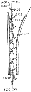
FIGS. 26 and 27 show an alternative configuration link 1406 with a first prong
1410 and a second prong 1412, which terminate at pointed, sharpened first and
second prong ends 1414, 1416 respectively and are joined by a link body 1413.
A
link 1417 with a slightly different, more open configuration is shown in FIG.
27a. As
shown in FIG, 28, the prongs 1410, 1412 of the link 1406 extend generally
outwardly
from the body 1413 and generally longitudinally with respect to a longitudinal
axis
1416 of a strand 1408, and form opposite, acute angles therewith. The angular
orientations of the Iirongs 1410, 1412 provide a one-way orientation for
engagement
CA 02643527 2008-10-14
WO 2008/140439 PCT/US2006/014507
i i -20-
in a first direclion and a disengagement orientation in the opposite
direction. Each
Ifnk 1406 can be integrally formed from a single length of suitable, suture-
like
material with suitable memory, flexibility/rigidity and biocompatibility
characteristics.
A U-shaped loop 1420 Is formed between the prongs 1410, 1412.
Also as shown in FIG. 28, each loop 1420 receives a respective long prong
1410 from the adjacent link 1406 in a flexible engagement, which can be formed
by
thermal fusing, ultrasonic welding, adhesive or any other suitable fastening
devlce or
method. For example, the link prongs 1410 and the loops 1420 can be configured
for
the tongue-and-groove or snap fit, movable interconnection without the
necessity of
physically bonding the links 1406.
The strands 1408 can be secured together in forming the panel 1404 by
multiple, diagonal filaments 1422, which extend generally transversely,
horizontally,
longitudinally or, preferably, diagonally with respect to the panel 1404. Like
the links
1406, 1417 and 1440, the filaments 1422 can comprise a bioabsorbable or other
biocompatible material. The filaments 1422 are preferably highly flexible and
thin.
FIG. 29 shows the screen panel 1404 in a compressed configuration whereby the
first, long prongs 1410 are pivotably received within the respective loops
1420 of
adjacent links 1406. FIG. 30 shows such pivotal action of the links 1406
(dashed
lines) for aecommociating relative tissue movement on either side of the
tissue
separation.
The screen 1402 Includes a pre-installation enclosure assembly 1424
comprising front and back backing sheets 1426, 1428, which can be provlded
wfth a
suitable releasable adhesive 1428. The backing sheets 1426, 1428 preferably
comptise paper or other material (e.g., Styrofoam® material), which is
relatively
stiff (as compared tn the relatively flimsy panel 1404) for maintaining the
flat shape of
the closure screen 1402 during handling and placement in the patient and for
protection from the sharpened prong tips. An outer edge handling strip 1430 is
mounted on the upper edge of perimeter 1432 of the panel 1404 (FIG. 25) and is
adapted for grasping manually or with instruments in order to facilitate
handling,
alignment and placement.
An alternative embodiment or aspect of the present invention is shown in FIGS.
31-33 and includes a modified clip comprising a dual-loop link 1556. Each link
1556
includes first and second prongs 1560, 1562 terminating at respective first
and
CA 02643527 2008-10-14
WO 2008/140439 PCT/US2006/014507
I 2~~
second ends 1564, 1566, Proximal and distal loops 1570, 1571 are provided
adjacent to first and second prongs 1560, 1562 respectively.
FIG. 34 shows a modifled closure screen construction 1624 using the clips
1604 mounted on a flexible matrix 1626 comprising flexible strips 1628
flexibly
interconnected in parallel relation by cross strands 1630. The strips 1628 can
be
penetrated by the prongs 1614, 1616 whereby all of the clips 1604 can be
mounted
on one side of a two-sided closure screen 1624. Atternatively, clips 1604 can
be
mounted on both sides of the strips 1628 in a two-sided closure screen, or on
either
side with all of the prongs pointing out for a single-sided closure screen.
FIG. 34a shows atternative clip constructions. Clip 1632 has interior prongs
1614 and edge prongs 1616 extending from one face at the top and from the
other
face at the bottom. Clip 1634 has upper prongs 1614, 1616 extending from
opposite
faces, and lower prongs 1614, 1616 likewise extending from opposite faces.
Clip
1636 includes only one each Interior prong 1614 and edge prong 1616, which can
extend outwardly from the same face (as shown), or can extend outwardly from
opposite faces.
FIG. 35 shows a clip 1632 approximating a tissue separation 4. The respective
prongs 1614, 1616 are embedded in the opposed tissue portion edges 12a,b.
Relative movement of the tissue can further secure the prongs 1614, 1616,
whereby
the edges 12a,b are drawn together for healing.
FIGS. 36 and 37 show a closure screen 1602 comprising another aspect or
embodiment with multiple, independent rigid clips 1604 on a flexible mesh
matrix
1606. Each clip 1604 includes first and second faces 1608, 1610 and a
perimeter
1612- Interior prongs 1614 are punched out of the clip 1804, thereby forming
clip
openings 1615, and perimeter prongs 1616 are punched out adjacent to the
perimeter 1612, thereby forming notches 1618. The closure screen 1602 is
formed
by threading mesh material connector strands 1620 through the clip openings
1615,
and securing the strands 1620 together in a crisscross pattern as shown in
FIG. 36.
The clips 1604 can be alternatingly oriented such that their respective prongs
1614
and 1616 extend from both sides of the screen 1602 (as shown) for two-sided
engagement, or they can extend from one face only for single-sided engagement.
FIG. 38 shows several constructions of clips 1852, 1858, 1864 and 1870,
stamped from sheet metal or other suitable material and having respective
bodies
CA 02643527 2008-10-14
WO 2008/140439 PCT/US2006/074507
-22-
comprising bases 1854, 1860, 1866 and 1872 with sharpened, respectlve prongs
1856, 1862, 1668 end 1874 projecting therefrom. FIG. 39 shows yet another clip
construction 1876 placed in a woven screen or mesh structure 1878, such as
those
described above, generaliy coplanar with a clip base 1880. Each clip 1876 has
a pair
of prongs 1882 projecting outwardly therefrom. The clips 1852, 1858, 1864 and
1870
are adapted for attachment to such screen or mesh structures, resulting in
configurations as shown In FIGS. 40-43.
FIGS. 44-49 show different bent-wire clip constructions adapted for mounting
on flexible screen or mesh structures_ A clip 1802 with a generally
rectangular base
1804 and a single prong 1806 projecting outwardly therefrom is shown in FIGS.
44
and 47. FIGS. 45 aiid 48 show a variant clip 1808 with a generally rectangular
base
1810 and prongs 1812. FIGS. 46 and 49 show another variant clip 1814 with a
generally U-shaped base 1816 and a pair of prongs 1818 projecting outwardly
therefrom. The bases 1804, 1810 and 1818 are adapted to lie generally in a
plane
formed by the screen or mesh structure, with the prongs 1606, 1812 and 1818
projecting outwardly therefrom at suitable acute angles, such as about 30-45
degrees_ The prongs can have sharpened tips, as shown.
FIG. 50 shows a clip 1902 comprising another altemative embodiment clip
configuration. As shown in FIGS. 51 a-c, clip configurations 1902a-c can be
formed
with four each primary prongs 1904 and four each secondary prongs 1906, which
can extend from one or both faces of a body 1908 of a respective clip 1902.
FIGS,
52a-c show side eI.evations of the clip configurations 1902a-c. A center slot
1903 is
formed in the body 1908 and notches 1905 are formed around its perimeter. The
center slot 1903 and the notches 1905 are adapted to receive filaments or
other
flexible members in a closure screen matrix including multiple clips 1902,
whereby
the clips 1902 can be somewhat fixed in position in a flexible closure screen
construction.
FIGS. 53 and 53a show another alternative embodiment clip configuration
1910 with curved pfimary prongs 1912 and straight secondary prongs 1914. The
curvature of the prirnary prongs 1912 facilitates drawing the separated tissue
portions 12a, 12b together, as shown in FIG. 53a and as presented by the
lateral
force arrows 1916. Such lateral forces can be applied with a NPWT device, such
as
The V.A.C,® System.TM_ manufactured by Kinetic Concepts, Inc. of San
CA 02643527 2008-10-14
WO 2008/140439 PCT/I7S2006/014507
-23-
Antonio, Tax. The secondary prongs 1914 help prevent disengagement when the
closure screen is subjected to a downward (i.e. into the body) force as
represented
by a force arrow 1917.
FIGS. 54 and 54a show another altemative embodiment clip configuration with
a curved body 1922. The configuration causes a trailing primary prong 1924 to
engage and penetrate tissue first, whereafter the clip 1920 rotates, embedding
a
leading primary prong 1926. The torque (clockwise as shown by torque arrow
1927)
Imparted to the clip 1920 by a tugging force, for example along the force
arrow 1928
on an encircling filament 1929, tends to facilitate secure anchorage in tissue
12b.
FIGS. 55 and 55a show another alternative embodiment clip-configuration
1930 with flexible, collapsible prongs 1932, 1934, which are collapsed when
the clips
are between backing screens 1936a,b. When the backing screens 1936a,b are
removed (FIG. 55a), the prongs 1932, 1934 spring outwardly to extended
orientations and are adapted for penetrattng the tissue 12b.
The altemative configuration clips 1910, 1920 and 1930 can be formed from a
common clip template, such as that shown at 1902 in FIG. 50, with a bendable
body
and prongs adapted for bending Into various desired configurations, Moreover,
the
clips can be mounted in various screen matrices.
FIG. 56 shows another atternative embodiment clip configuratlon 1940 with
primary and secondary prongs 1942, 1944 having respective barbs 1942a, 1942b.
FIG. 57 shows another altemative embodiment clip configuration 1950 with
primary
and secondary prongs 1952, 1954 having respective barbs 1952a, 1952b. FIG, 56
shows another alternative embodiment clip configuration 1960 with
quadrilateral
primary and secondary prongs 1962, 1964 having respective trocar-shaped ends
1962a, 1964a. Various other clip, base and prong configurations, combinations
and
orientations can be utilized with the present invention.
FIG. 59 shows a closure clip system 1970 comprising another aitemative
embodiment of the present Invention. The system 1970 includes a screen 1972,
which can comprise, for example, any of the clip and screen constructions
described
3o abeve_ The screen '1972 is placed within the tissue separation 4 and an
extension
1974 is folded over onto the skin surface on either or both sides of the
tissue
separation 4. Affixing the screen, or the strips comprising same, helps to
support the
links and clips in position against downward loads. The adhesive on the screen
or
CA 02643527 2008-10-14
WO 2008/140439 PcrIUs2006i014507
-24-
strips would not adhere to the wet tissue of the separation edges, but would
appear
to the dry skin surface 6. The screen or strips can be made of rapidly
dissolving,
bloabsorbable material reinforced with longitudinal strands of slower
dissolving
material, similar to the construction of strand reinforced tape available as
STERI-
STRIP,RTM. from the 3M Company of St. Paul, Minn. With the extension 1974
foided over the skir i surface 6 and the rest of the clips above the wound 4
removed
or cut away, the extension(s) 1974 can be affixed to the skin surface 6 with
STERI-
STRlP or some other suitable tape 1976. In lieu of-or in addition to the tape
1976,
surgical staples 1978 can be used to close the tissue separation and affx the
1o extension(s) 1974 to the skin surface 6. Lateral closure forces can
optionally be
applied to the tissue separation 4 shown in FIG. 59 by applying a NPWT source
1980 such as The V.A.C.® System.TM, over the closure. A suitable drape
1982
can be applied over the negative pressure source 1980 in sealing relation with
the
skin around the per=imeter. I
FIG. 60 shows a load-deforrnatlon curve showing the relationship of tension
measured in pounds per prong and extension of the system measured in
sixteenths
of an inch using a rnultiple-clip screen simiiar to the closure screen 1602
shown in
FIG. 36. The screen was retained between two pieces of raw beefsteak, which
were
subjected to varying shear stress (tensile) forces, as plotted on the Y axis
of the
graph in FIG. 60. Compression forces equal to 0.341 pounds/prong were applied
to
the beefsteak pieces with the closure screen clamped therebetween. Such
compression forces were applied mechanically to produce the load-deformation
curve shown in FIG. 60. FIG. 61 shows a load-deformation curve for varying
compression forces at a constant tension force of 0.341 pounds/prong. A
theoretical
point projected frorn the load-deformation curve of FIG. 61 represents 100
mmHg of
vacuum compression, as applied with The V.A.C.® System.TM. in the model
tested. FIG. 80 shows that increasing tension loads produce increasing
extension of
the model (positive relationship). FIG. 61 shows that compression loads and
extension have an inverse relationship, with greater extension occun'ing with
lesser
compression loads
It is to be understood that while certain forms of the present invention have
been illustrated anci described herein, it is not to be limited to the
specific forms or
an-angement of pai ts described and shown.