Note: Descriptions are shown in the official language in which they were submitted.
CA 02643776 2008-08-26
WO 2007/109147 PCT/US2007/006666
-1-
SYSTEM AND METHOD FOR CREATING A STABLE OPTICAL INTERFACE
CROSS REFERENCE TO RELATED APPLICATION(S)
The present application claims priority to a U.S. patent application, bearing
serial
number 11/378,538, filed on March 17, 2006, entitled "System and Method for
Creating
a Stable Optical Interface." The entire contents of the U.S. patent
application are hereby
incorporated by reference herein.
0
BACKGROUND OF THE INVENTION
Field of the Invention
The present invention relates generally to stabilizing an optical interface
and,
more specifically, to creating a reproducible and stable optical interface
between
biological tissue and an optical blood glucose sensor.
Related Art
Monitoring of blood glucose concentration levels has tong been critical to the
treatment of diabetes in humans. Current blood glucose monitors involve a
chemical
reaction between blood serum and a test strip, requiring an invasive
extraction of blood
via a lancet or pinprick. Small handheld monitors have been developed to
enable a
patient to perform this procedure anywhere, at any time. But the inconvenience
of this
procedure -- specifically the blood extraction and the use and disposition of
test strips --
has led to a low level of compliance. Such low compliance can lead to serious
medical
complications. Thus, a non-invasive method for monitoring blood glucose is
needed.
Studies have shown that optical methods can detect small changes in biological
tissue scattering related to changes in levels of blood sugar. Although highly
complex, a
first order approximation of monochromatic light scattered by biological
tissue can be
described by the following simplified Equation 1:
IR = Io exp[-(fue +,u.,)L] Eq. 1
where IR is the intensity of light reflected from the skin, Io is the
intensity of the light
illuminating the skin, a is the absorption coefficient of the skin at the
specific
CA 02643776 2008-08-26
WO 2007/109147 PCT/US2007/006666
-2-
wavelength of light, s is the scatter coefficient of the skin at the specific
wavelength of
light, and L is the total path traversed by the light. From this relationship,
it can be seen
that the intensity of the light decays exponentially as either the absorption
or the
scattering of the tissue increases.
It is well established that there is a difference in the index of refraction
between
blood serum/interstitial fluid (blood/IF) and membranes of cells such as blood
cells and
skin cells. (See, R.C. Weast, ed., CRC Handbook of Chemistry and Physics, 70th
ed.,
(CRC Cleveland, Ohio 1989)). This difference can produce characteristic
scattering of
transmitted light. Glucose, in its varying forms, is a major constituent of
blood/IF. The
variation of glucose levels in blood/IF changes its refractive index and thus,
the
characteristic scattering from blood-profused tissue. In the near infrared
wavelength
range (NIR), blood glucose changes the scattering coefficient more than it
changes the
absorption coefficient. Thus, the optical scattering of the blood/IF and cell
mixture
varies as the blood glucose level changes. Accordingly, an optical method
presents a
potential option for non-invasive measurement of blood glucose concentration.
Non-invasive optical techniques being explored for blood glucose application
include polarimetry, Raman spectroscopy, near-infrared absorption, scattering
spectroscopy, photoacoustics and optoacoustics. Despite significant efforts,
these
techniques have shortcomings such as low sensitivity, low accuracy (less than
current
invasive home monitors) and insufficient specificity of glucose concentration
measurement within the relevant physiological range (4-30 mM or 72-540 mg/dL).
Accordingly, there is a need for an improved method to non-invasively monitor
glucose.
Optical coherence tomography, or OCT, is an optical imaging technique using
light waves that produces high resolution imagery of biological tissue. OCT
creates its
images by focusing a beam of light into a medium and interferometrically
scanning the
depth of a linear succession of spots and measuring the absorption and/or the
scattering
of the light at different depths in each successive spot. The data is then
processed to
present an image of the linear cross section of the medium scanned. It has
been
proposed that OCT might be useful in measuring blood glucose.
CA 02643776 2008-08-26
WO 2007/109147 PCT/US2007/006666
-3-
SUMMARY OF THE INVENTION
Embodiments of the invention are directed to systems and methods for creating
a
stable and reproducible an optical interface for performing measurements such
as non-
invasive blood glucose measurements in biological tissue. Such embodiments can
utilize
a dual wedge prism sensor attached to a disposable optic that comprises a
focusing lens
and an optical window. The disposable optic can be adapted to adhere to the
skin to
allow a patient to take multiple readings or scans at the same location. The
disposable
optic can include a Petzval surface placed flush against the skin to maintain
the focal
point of the optical beam on the surface of the skin. In some embodiments, the
integrity
of the sensor signal can be enhanced by varying the rotation rates of the dual
wedge
prisms over time in relation to the depth scan rate of the sensor. As well, a
medium can
be injected between the disposable and the skin to reduce the effect of
refractive index
mismatch and to enhance the signal collection of the sensor.
One drawback associated with using OCT for monitoring blood glucose is the
signal noise associated with optical interferometry, also known as speckle. As
discussed
in U.S. Application 10/916,236 by M. Schurman, et al, entitled "Method and
Apparatus
for Monitoring Glucose Levels In A Biological Tissue," to reduce speckle, a
glucose
monitor incorporating OCT methodology may scan a beam of collimated light
continuously and laterally across a two-dimensional surface area of a
patient's tissue or
skin, while interferometrically scanning the tissue in depth. Preferably, the
scanning is
accomplished with a small, lightweight, and robust mechanism that can be
incorporated
into a sensor to be used in a fiber-optics based product or, alternately, a
non fiber-optics
based product. One main objective of using this type of sensor is to generate
a
reproducible stable optical interface between the subject's skin and optical
path of the
sensor in order to take multiple readings from the same lateral location on
the skin while
maintaining the integrity of the optical interface. As discussed below, there
are multiple
problems associated with providing and maintaining a stable and reproducible
optical
interface between an OCT sensor and the skin of a patient.
Two Basic Optic Designs
Two well known sensor designs that use OCT are schematically shown in Figs. 1
and 2. Fig. 1 shows a design based on the use of two rotating wedge prisms to
change
CA 02643776 2008-08-26
WO 2007/109147 PCT/US2007/006666
-4-
the angle of collimated light incident on a focusing lens. In Fig. 1, incoming
light beam
101 hits a collimating lens 102, which splits the beam 101 into multiple
parallel beams
of light, or collimated light 103. The collimated light 103 then passes
through one or
more wedge prisms 104, which are rotating at predefined rates. As shown in
Fig. 1, dual
rotating wedge prisms 104 generate an angular deviation in the collimated
light 103
from the optical axis of the sensor, which is the "centerline" axis passing
through the
elements of the sensor, perpendicular to the surface area of skin 109 to be
tested. By
deviating the angle of the collimated light 103, the focal point of the light
moves around
on a focal plane of an optical window 108 that is flush against the skin 109,
thereby
scanning different lateral locations on the skin 109. As shown at 105, once
passing
through wedge prisms 104, the parallel rays of collimated light 103 may be
angled away
from the optical axis, depending on what portion of the wedge prisms 104 the
collimated
light 103 passes through. The angled beams 105 then pass through a focusing
lens 106,
and begin to focus together to a focal point 107 at the bottom surface of an
optical
window 108..
Fig. 2 shows a similar concept to Fig. 1, however the dual wedge prisms 104 of
Fig. 1 are replaced with an angled mirror 201, for example, a 45 degree angled
mirror,
that oscillates along two axes, thereby deviating the angle of collimated
light 103 from
the optical axis in order to move the focal point 108 around on the surface
area of skin
109. Accordingly, this OCT sensor design is well known in the art. Both
designs
facilitate scanning an area of skin by deviating the angle of collimated beam
103 from
the optical axis, thereby moving the focal point 107 a proportional distance
laterally in
the focal plane along the bottom of the optical lens 108, and, accordingly,
along the
surface area of the patient's skin 109.
While*both sensor designs provide mechanisms for incorporating OCT into a
noninvasive blood glucose sensor, there are several drawbacks associated with
the above
designs as described below.
Variations in Optical Path Length
One drawback associated with the dual wedge prism sensor design of Fig. 1 is
illustrated in Fig. 3. In an interferometer, the optical path length of a beam
of light is
CA 02643776 2008-08-26
WO 2007/109147 PCT/US2007/006666
-5-
determined by the physical or geometric path length of the beam and the index
of
refraction of the medium which the beam is passing through as shown in
Equation 2:
LoPr = n= LcEO Eq. 2
where "LoPT" is the optical path length, "n" is the index of refraction, and
"LcEO" is the
geometric or physical path length
As shown in Fig. 3, depending on the position of the wedge prisms 104 at the
time the collimated beam 103 shines through, while the geometric path length
of the
collimated beam 103 stays the same, the index of refraction changes due to the
changing
thickness of the wedge prisms 104 as the prisms rotate, thereby altering the
optical path
length of the collimated beam 103. This continuous change in the thickness of
the
wedge prisms 104 continuously alters the optical path length of the collimated
beam 103
as it passes through. As shown in Fig. 3, the placement of the wedges may
extend the
length of the optical path, making it seem as though the skin 109 is moving
away from
the sensor. Thus, three optical scans taken through the dual wedge prisms 104
when the
prisms 104 are in different rotated positions produce three scans beginning at
different
positions in depth. Since the sensor data is an average of multiple scans, if
each scan
begins at a different position in depth, the resulting ensemble average will
not be
representative of a true averaging of multiple scans.
For example, in Fig. 3, when the collimated beam 103 passes through the
thinnest area of the wedge prisms 104, as shown at 301, the sensor begins to
collect data
at Depth A, interpreting the interface between the optical window 108 and the
skin 109
to be at Depth A, as shown at 302. However, when the collimated beam 103
passes
though a thin portion of the first wedge prism and a thick portion of the
second wedge
prism, as shown at 302, the sensor begins to collect data at Depth B,
interpreting the
interface between the optical window 108 and the skin 109 to be at Depth B, as
shown at
304. Further, when the collimated beam 103 passes through the thickest portion
of both
wedge prisms, as shown at 305, the sensor begins to collect data at Depth C,
interpreting
the interface between the optical window 108 and the skin 109 to be at Depth
C, as
shown at 306. Since typically multiple scans (e.g., greater than 100 scans)
are taken and
CA 02643776 2008-08-26
WO 2007/109147 PCT/US2007/006666
-6-
then averaged to reduce speckle, scans taken at different positions in depth
cannot be
averaged. Thus, a solution to this problem is desired.
Another drawback associated with the dual wedge prism sensor is the distortion
of the scan along the depth axis or z-axis of the light beam entering and
exiting the skin.
If the rotation speed of the wedge prisms 104 is several orders of magnitude
larger than
the depth scan rate of the optical sensor, then the depth scale measured by
the scan is
either "stretched" or "shrunk" by the entire amount of the difference in
optical path
induced by the changing thickness of the wedge prisms 104. However, if the
rotation
speed of the wedge prisms 104 is much slower than the depth scan rate, then
the
changing thickness of the wedge prisms 104 has a minimal effect on the depth
scale.
For example, if the depth scans occur at 60 Hz, which means that the sensor
completes
one depth scan vvithin in 1/60'` of a second, and the prisms rotate at 3600
rpm, then each
wedge prism makes a full rotation during the time it takes the sensor to
complete one
depth scan. Because the thickness of each wedge prisms varies as the prisms
rotate, the
optical path length changes during each depth scan, which distorts the depth
data
collected by the sensor by changing the depth scale during a single scan.
Thus, there is
an optimization that must occur between the depth scan rate and the prism
rotation rate
such that the entire surface area is thoroughly scanned while minimizing the z-
axis scan
distortion.
Scan Pattern Stability
Accordingly, it is desired is that each depth scan be taken at a different
lateral
position on the surface of the skin 109 such that the ensemble of all the
depth scan
positions are randomly and uniformly distributed throughout the scan region.
The lateral
locations of each depth scan must be spatially independent to 1) effectively
encompass
regions of blood glucose change during a sensor reading and 2) effectively
reduce
speckle. However, a problem associated with the dual wedge prism sensor in
Fig. 1 and
the oscillating mirror sensor in Fig. 2 is the inability to capture each depth
scan position
due to the angular velocity of the wedge prism(s) 104 or the oscillation rate
of the angled
mirror 201 being harmonic in phase with the depth scan rate of the optical
sensor, i. e.,
the frequency of the angular velocity is a multiple or integral of the depth
scan rate of
the sensor. When either the angular velocity or oscillation rate is an
integral of the depth
CA 02643776 2008-08-26
WO 2007/109147 PCT/US2007/006666
-7-
scan rate, the two rates "beat" against each other, and produce a loss of
conformal
coverage of the surface area of the skin 109 being scanned.
As shown in Fig. 4B, when using a single rotating wedge prism or oscillating
angled mirror in a sensor as described above, the optimal result of multiple
depth scans
is a circle pattern on the surface area of the skin 109, which each "dot"
representing a
depth scan. Each depth scan occurs along the path of this circle pattern,
effectively
breaking the circle up into a series of scanned points. However, if the
angular velocity is
an integral or harmonic of the depth scan rate, the depths scans begin to
overlap in
location, thereby producing an incomplete circle pattem and a loss of
spatially
independent depth scans, as shown in Fig. 4A. With an overlap of depth scans,
the same
locations of tissue are scanned, causing less speckle reduction and poor
imaging of
structures within the scanned tissue. The problem becomes even more pronounced
in
the case of a sensor with two wedge prisms, as shown in Fig. 4C.
Focal Plane Instability
Another challenge presented by both the wedge prism design in Fig. I and the
oscillating mirror design in Fig. 2 is the inability to maintain the focal
point 107 of the
focused collimated beam on the focal plane, or the interface between the
optical window
108 and the surface area of the skin 109 being scanned. Optical lenses do not
project an
image onto a flat plane, such as the flat bottom surface of the optical window
108, but,
instead, naturaliy project an image onto a curved surface, much like the
curved interior
of the eye. This curved surface is well known as a Petzval surface. Thus, as
the
collimated light 103 enters the focusing lens 106, the focal point 107 of the
collimated
light 103 traces out a curved focal plane or Petzval surface based on the
design of the
focusing lens 106, caused by the angular deviation from the optical axis due
to the
wedge prisms 104 in Fig. 1 or the angled mirror 201 in Fig. 2. Thus, the flat
bottom of
the optical window 108 does not allow the focal point 107 to remain on the
focal plane.
When the focal point 107 moves off of the Petzval surface, the efficiency of
the
focused light being collected begins to drop, since focal plane is where the
light capture
is maximized. Additionally, the depth scale of the focused light is affected
such that the
displacement of the focal point 107 off of the focal plane results in an
equivalent loss in
the depth scale of the signal. This results in a blurring of the optical axis,
causing
CA 02643776 2008-08-26
WO 2007/109147 PCT/US2007/006666
-8-
measurable details within the skin to be blurred or washed out. Thus, a
displacement of
the focal point off the focal plane results in a reduction in the sensor
signal intensity and
a blurring of the optical axis.
Additionally, optical lenses are not perfect. ' Therefore, as the focal point
107
moves away from the optical axis due to the rotating wedge prisms 104 or the
oscillating
angled mirror 201, the focused beam drifts away from the skin 109 and back
towards the
focusing lens 106, and, thus, moves off the focal plane. As discussed above,
when the
focal point 107 is no longer on the focal plane, the collection efficiency of
the light
drops, resulting in the collected data incorrectly indicating a reduction in
power. This, in
tum, alters the depth of the focused beam, thereby unwittingly washing out
details in the
skin and lowering the resolution and integrity of the scan.
Skin/Sensor Optical Interface
The surface of the skin is "rough" relative to the light entering and exiting
the
skin during an optical scan. This is well known as optical roughness.
Additionally, the
refractive index of the skin being scanned typically is different from the
refractive index
of the material of an optical window of a sensor. As shown in FIG. 5A, the
optical
window 503 is not necessarily flush against the surface of the skin 504, due
to optical
roughness 505 of the skin. Accordingly, as incident light 501 is directed
towards the
skin, some of the light is reflected and/or diffracted, as shown at 502,
because there is a
mismatch between the index of refraction of the optical window 503 and the
index of
re&action of the skin 504. This mismatch of refractive indices and, in
addition, the
space between the skin 504 and the optical window 503 due to the optical
roughness 505
reduces the reliability of data taken by the sensor.
Fig. 5B displays two scans taken at the same location on the skin but measured
at
different points in time with constant optical contact between the skin 109
and the
optical window 108 of a sensor. Such scans may be produced by either the dual
wedge
prism sensor of Fig. I or the angled mirror sensor of Fig. 2. Data line 506
represents an
averaged optical scan taken at Time 0 while data line 507 represents an
averaged optical
scan taken thirty minutes after Time 0. Typically, the focused beam hits the
interface
between the optical window 503 and the skin 504, a sharp rise or peak in the
signal is
produced, as shown at peaks 510 and 511. The signal then drops as the beam
moves
CA 02643776 2008-08-26
WO 2007/109147 PCT/US2007/006666
-9-
through the skin 504 and begins to rise again as the beam hits the interface
between the
epidermis and dermis layers, as shown at peaks 508 and 509. The signal again
drops
and continues to drop as the beam reaches the desired depth then returns back
to the
sensor.
As shown in Fig. 5B, while constant optical contact is maintained between the
skin 504 and the optical window 503 of the sensor, over time the optical
signal drifts, as
illustrated by the peaks at the interface between the dermis and epiderrnis
layers, which
rises over time, from peak 508 at Time 0 to peak 509 at Time 0 + 30 minutes.
However,
the peak at the interface between the optical window 503 and the skin 504
drops over
time, from peak 510 at Time 0 to peak 511 at Time 0 + 30 minutes. This change
in
signal intensity is due to a gradual change in the optical interface created
by an -
accumulation of sweat and skin oils at the interface of the optical window 503
and the
skin 504, as shown at 512 in Fig. 5C, which serves as an optical transition
for the
incident light 501 to efficiently travel from the optical window 503 to the
skin 504.
Additionally, the accumulation of sweat and skin oils smoothes out the optical
roughness
of the skin. Although the refractive index between.the optical window 503 and
the skin
504 will stabilize or reach an equilibrium value due to sweat, oil, and other
fluids
produced by the skin over time, this process could take upwards of 60-90
minutes.
Unfortunately, these changes in signal intensity over this extended period of
time may
completely mask the changes that are occurring along the OCT signal, and thus
prevent
proper correlation of changes in the OCT signal to changing glucose levels, as
discussed
in U.S. Provisional Applications Nos. 60/671,007 and 60/671,285, both entitled
"Method For Data Reduction and Calibration of an OCT-Based Blood Glucose
Monitor." Thus, multiple scans taken over time cannot produce a reliable
measurement
from the same lateral location on the skin. In addition, a patient would be
required to
place the sensor onto his or her skin and wait 60-90 minutes before using it,
in order to
receive reliable and reproducible results, which creates an inefficient
sensor.
Thus, a need exists for an optical sensor for measuring blood glucose levels
and
other physiological effects that overcomes the deficiencies discussed above.
According to one embodiment of the present invention, a system for generating
a
stable and reproducible optical interface includes an OCT-based interferometer
connected to an optical sensor that utilizes a collimated beam of light and
comprises
CA 02643776 2008-08-26
WO 2007/109147 PCT/US2007/006666
-10-
dual wedge prisms to move the collimated beam to different lateral locations
on the skin,
and a disposable optical lens apparatus that attaches to the skin surface
using an
adhesive, where the disposable optical lens apparatus comprises a focusing
lens and an
optical window that interfaces directly with the skin. Alternately, the
optical sensor
may utilize an angled mirror that oscillates along two axes to move the beam
of light to
different lateral locations on the skin surface.
By using a disposable optical lens apparatus, a patient may place the sensor
onto
the optical lens apparatus, take a reading, then remove the sensor and leave
the optical
lens apparatus attached to his or her skin, for example, on an arm. When
another
reading is taken at a later time, the patient simply reattaches the sensor to
the optical lens
apparatus, guaranteeing that the lateral location of the sensor remains the
same, in order
to produce a comparable optical scan. At some point in time, the patient may
remove
the disposable optical lens apparatus and discard it, only to replace it with
another.
Thus, the disposable optical lens apparatus may be made from different
materials, such
as, for example, glass, plastic, or other polymer material, and may be
customized for
each patient's needs. A computer also may be connected to the optical sensor
and/or
interferometer, where the computer manipulates the sensor data and produces
physiological data, such as blood glucose levels.
Accordingly, one exemplary embodiment is directed to a lens assembly for
coupling an optical system (e.g., an OCT interferometric system) to the skin
of a patient.
The assembly can be adapted to be disposable after one or more uses. The
assembly can
include a lens, such as a focusing lens to direct light delivered from the
optical system.
An optical window can also be included, which can be configured to press upon
the
patient skin. The window can allow focused light to travel therethrough. The
optical
window can be configured in a pedestal shape, or to have a Petzval surface,
which can
correspond to a particular lens. The lens, the optical window, or both can be
configured
to enhance the optical power of light that is reflected back through the
window. When
the optical window is so configured, it can also be adapted as a reflection-
compensated
Petzval surface. A skin-contacting medium can be disposed on the optical
window to
reduce the effect of index of refraction mismatch and/or to reduce the effect
of optical
surface roughness.
CA 02643776 2008-08-26
WO 2007/109147 PCT/US2007/006666
-11-
The assembly can further include an apparatus for holding the lens and/or the
optical window. For example, the apparatus can hold a lens and an optical
window a
predetermined distance apart from each other. The apparatus can be configured
to be
attached to a patient's skin using adhesive. The apparatus can also be
detachably
coupled to the optical system, for example by the use of one or more
connectors attached
to the apparatus or other portions of the lens assembly.
As mentioned above, multiple scans may be taken during a single sensor use and
then averaged together to reduce or remove the speckle associated with an OCT-
based
system. To account for variations in the optical path length of the collimated
beam
produced by the varying thicknesses of the rotating dual wedge prisms, the
resulting
scan data is manipulated. According to an embodiment of the present invention,
a
method for resolving the variations in optical path length includes the steps
of (i)
locating the first peak, which represents the interface between the optical
window and
the patient's skin, of the first scan taken by the sensor, (ii) locating the
first peak in each
subsequent scan taken during the single use, and (iii) normalize each first
peak in the
subsequent scans against the peak of the first scan. The method further
comprises the
step of (iv) averaging the normalized scans to produce an averaged scan
result. To
locate the peaks, algorithms such as Gaussian peak fitting and second-
derivative residual
methods may be used and are well known within the field of the invention.
An alternate embodiment of the present invention presents a more time-
efficient
method for resolving the variations in the optical path length. The method
includes the
steps of (i) setting a peak threshold trigger in the signal intensity and (ii)
holding off of
true data acquisition until the signal hits the threshold trigger. Once signal
reaches the
threshold trigger, the system begins to collect the scan data Different
optical
arrangements may require different threshold triggers, where optical
arrangements may
vary due to the angle of the wedge prisms in the optical sensor. However, to
optimize
the threshold trigger, at least a 10 db difference may exist between the
threshold trigger
and the first peak intensity value, where the signal intensity is measured in
decibels. For
example, if the first peak measures 60 db, then the threshold trigger is set
to less than or
equal to 50 db. Additionally, the threshold trigger may be set above the
highest noise
peak produced by the signal until the focused beam hits the optical window,
where the
signal begins to rise in intensity. For example, if the highest noise peak is
30 db and the
CA 02643776 2008-08-26
WO 2007/109147 PCT/US2007/006666
-12-
first intensity peak reaches 60 db, then setting a threshold trigger between
30 db and 50
db is preferable. Since the most useful data is acquired beginning typically
around 150
microns in depth (within the dermis layer of the skin), and the first peak in
intensity
typically occurs around 20 or 30 microns in depth, by setting a threshold
trigger near the
rise of the first signal peak, any mismatch in the optical path length will be
less than half
the coherence length of the optical sensor system, which is below the
resolution of the
interferometer.
The coherence length of the optical sensor system, which is a measure of the
depth resolution of the system, is broadly inversely related to the bandwidth
of the
optical source of the system, such as, for example, a superluminescent diode.
Thus, as
the bandwidth of the optical source increases, the coherence length of the
system
decreases, and accordingly, the depth resolution of the system improves. The
interface
between the optical sensor and the skin has a specific peak intensity value,
for example,
60 dB, and the width of the peak is the coherence length of the optical sensor
system, for
example, 30 microns. However, for each depth scan, the optical sensor/skin
interface
peak doesn't always occur at the exact location in depth, i.e., the peak
location may be
offset by a few microns in depth. If, for example, the threshold trigger is
set to a value
that is near the signal peak intensity value, then the offset of the location
of each peak
value for each depth scan cannot be more than a fraction of the coherence
length, which
is below the resolution of the optical system. Thus, the offset does not
affect the data
collected by the sensor and the depth scans may be averaged to reduce speckle
and to
produce an accurate sensor reading.
According to an aspect of the embodiment, the optical sensor system may be set
to acquire data once the focused beam reaches a specific structural feature.
For
example, the threshold trigger may be set to correspond to an intensity value
of light
once the focused light reaches the interface between the skin and the optical
window,
which may occur, for example, at a depth of one-half of a millimeter ("mm").
Thus, if
the optical window/skin interface occurs at an intensity value of 60 dB, then
the trigger
threshold may be set to a value of 50 dB. Therefore, the optical window/skin
interface
becomes a reference point for each depth scan to be lined up against, in order
for the
depth scans to be averaged.
CA 02643776 2008-08-26
WO 2007/109147 PCT/US2007/006666
-13-
According to another embodiment of the present invention, a method for
minimizing the distortion in the depth scale due to change in thickness of the
dual wedge
prisms as they rotate includes the step of optimizing the depth scan rate
versus the prism
angular velocity in order to minimize any distortion of the scan in depth, or
along the z-
axis. If the depth scans occur at a rate at or near the angular velocity of
the wedge
prism, then each depth scan performed by the sensor occurs within a time
period close* to
the time period of a single rotation of the wedge prisms. As discussed above,
because
the wedge prisms are not a uniform thickness and the thickness affects the
refractive
index and the optical path length, as the prisms rotate, the depth of each
depth scan is
distorted within a single scan because the optical path length is changing
during a single
scan when the time periods are close or exact. To prevent this problem, the
method
includes the step of setting the angular velocity of the wedge prisms to
a.value such that
the lateral position of the scan spot on the skin surface moves a distance
that is less than
ten times ("l OX") a diameter of the scan spot during the data acquisition of
a single
depth scan. This method allows the optical path length to remain stable during
each
depth scan taken.
In yet another embodiment of the present invention, a method for stabilizing
the
scan pattem of the optical sensor includes the step of (i) setting the angular
velocity of
the wedge prisms to a non-harmonic phase value in relation to the depth scan
rate. By
doing so, conformal coverage of the scanning area may be achieved. However,
due to
the drift of the angular velocities common in such a system, it is likely that
the angular
velocity will drift into a harmonic phase of the depth scan rate, and
conformal coverage
will be lost. Thus, the method further comprises the steps of (ii) varying the
angular
velocities of the dual wedge prisms during the total time of an entire sensor
reading (i.e.,
1500 scans), and (iii) varying the angular velocities of each wedge prism with
respect to
the other wedge prism over the total time of the sensor reading. By varying
both the
angular velocity of the wedge prisms over time in relation to the depth scan
rate, and the
angular velocity of each wedge prism over time in relation to the other wedge
prism,
conformal coverage of the scan surface area is maximized. According to an
aspect of
the present embodiment, the method may be modified to vary the oscillation
rate of the
angled mirror in the mirror sensor such that the oscillation rate in both axes
of
movement is not a harmonic of the depth scan rate of the sensor.
CA 02643776 2008-08-26
WO 2007/109147 PCT/US2007/006666
-14-
According to an alternate embodiment of the present invention, in an optical
sensor with rotating dual wedge prisms, two harmonically related phase signals
may be
used to vary the angular velocities of each wedge prism so long as the time
period of one
phase signal associated with one of the wedge prisms is several times longer
than the
time period of one phase signal associated with the other wedge prism, and
both phase
signals are non-harmonic values of the depth scan rate. For example, if 2.0 Hz
and 0.02
Hz are the angular velocities maintained over time of the wedge prisms, and
the depth
scan rate is 57 Hz, the problem is minimized and conformal coverage of the
scan paitern
is maximized. The embodiment encompasses numerous ways to vary the angular
velocity of the wedge prisms, for example, a saw tooth wave, a sinusoidal
wave, a
triangle wave, etc.
In yet another embodiment of the present invention, a method for optimizing an
amount of light entering and exiting an area of skin includes modifying the
disposable
optical lens as described above by incorporating a dome shape to the bottom
surface of
the optical window. The dome shape can be designed to provide a Petzval
surface for
the focusing lens, and follows the variation in the focal point displacement
that occurs as
the focal point deviates from the optical axis through increasing incidence
angles of the
focused beam. Thus, the Petzval surface can correct astigmatic or field
curvature
aberrations that may otherwise affect the light that ultimately reaches the
sensor. The
Petzval surface can rest between the skin and the optical window of the
disposable.
Additionally, the Petzval surface can also improve the interface between the
disposable
apparatus and the skin by stabilizing the local pressure on the skin in the
vicinity of the
depth scans. For a flat optical window, the pressure on the skin is
distributed widely
across the entire skin interface of the optical window, which is a relatively
wide area.
This wide distribution of pressure reduces the optical coupling efficiency of
the sensor.
Accordingly, the dome shape of the Petzval surface concentrates the pressure
on the skin
tissue towards the center of the dome where the scan is taking place, which
optimizes
the optical coupling efficiency of the sensor.
According to another aspect of the present embodiment, a pedestal shape may be
incorporated onto the skin interface side of the optical window, to stabilize
the local
pressure on the skin in the vicinity of the depth scans by distributing the
pressure along
the plateau edge of the pedestal, thereby improving the optical contact.
CA 02643776 2008-08-26
WO 2007/109147 PCT/US2007/006666
-15-
The Petzval surface facilitates maintaining the focal point on the surface
skin and
reducing the blurring of the optical axis and maximizing the uniformity of
light captured
entering and exiting the skin at all points in the area scan. Using the
Petzval surface,
whenever the focused beam hits the surface of the skin, it is focused and
maximized,
providing the highest efficiency of the light as well as maintaining the same
distance in
depth that would be available along the optical axis due to the skin wrapping
around the
Petzval surface. The size of the Petzval surface is a function of the focusing
lens design
in the disposable apparatus. Both depth resolution and optical collection
efficiency are
optimized by maintaining the focal point on the Petzval surface.
According to another embodiment of the present invention, a method for
improving the optical interface between a sensor and a surface of the skin
includes the
step of using an index matching medium at this optical interface, where the
medium
improves and stabilizes the optical interface and provides an optical
transition for an
optimal amount of incident light from the sensor to pass through to the skin.
A wide
variety of mediums that can be used, each with differing optical properties
and
viscosities, such as, for example, fluids such as glycerin, saline, and
mineral oil, gels,
such as medical gels or a gel moleskin, or adhesive-type materials, so long as
the
refractive index of the medium is less than the refractive index of the
disposable
apparatus. Preferably, the index matching medium provides a thin conformal
coating on
the skin and the associated disposable interface, and smoothes the optical
roughness of
the skin, reducing the loss of incident light entering the skin. By using an
index
matching medium, a patient need not wait the 60-90 minutes for the interface
of the
disposable and the skin to stabilize, but may use the OCT sensor at any given
time by
simply connecting it to the disposable optical lens apparatus adhered to the
skin.
Additionally, the index matching medium smoothes out the relatively rough
surface of the skin, which may cause a scattering of the focused beam at the
skin
surface. Accordingly, the index matching medium coats the skin and reduces the
optical
roughness of the skin surface, thereby optimizing the intensity of the light
that goes into
and comes out of the skin.
CA 02643776 2008-08-26
WO 2007/109147 PCT/US2007/006666
-16-
BRIEF DESCRIPTION OF THE DRAWINGS
The present invention will be more readily understood from the detailed
description of the preferred embodiment(s) presented below considered in
conjunction
with the attached drawings, of which:
Figure 1 illustrates a rotating dual wedge prism optical scanning apparatus,
according to an embodiment of the present invention;
Figure 2 illustrates a mirror based optical scanning apparatus, according to
an
embodiment of the present invention;
Figure 3 graphically shows how the relative position of an object being
scanned
by a rotating wedge prism optical scanning apparatus changes due to the
orientation of
the wedge prism;
Figures 4A-4C illustrate the relationship between the angular velocity of one
or
more wedge prisms and the depth scan rate of a sensor in relation to the scan
pattern of
the sensor, according to an embodiment of the present invention;
Figure 5A presents a magnified view of the optical interface between an
optical
window and a surface of skin;
Figure 5B illustrates the effect of sweat and bodily fluids on the data
produced
by an optical signal;
Figure 5C presents a magnified view of the effect of sweat and bodily fluids
on
an optical interface between an optical window and a surface of skin;
Figure 6A presents an optical sensor system, according to an embodiment of the
present invention;
CA 02643776 2008-08-26
WO 2007/109147 PCT/US2007/006666
-17-
Figure 6B presents an optical scanning system, according to an embodiment of
the present invention;
Figure 7A presents a Petzval surface design for a disposable optical lens
apparatus, according to an embodiment of the present invention;
Figure 7B presents a pedestal surface design for a disposable optical lens
apparatus, according to an embodiment of the present invention;
Figure 7C presents a top view of a lens assembly in accord with an embodiment
of the present invention;
Figure 7D presents a side view of the lens assembly shown in Figure 7D;
Figure 8A presents a schematic diagram of a lens and optical window surface in
which reflection or refraction losses can occur;
Figure 8B presents a schematic diagram of a lens and optical window surface
which are configured to reduce the power losses of returned light, in accord
with an
embodiment of the invention;
Figure 9 presents a method of using an optical scanning apparatus to measure
blood glucose, according to an embodiment of the present invention;
Figure 10 presents a method for stabilizing a scan pattern of an optical
scanning
apparatus, according to an embodiment of the present invention;
Figure 11 A is a graphical illustration of varying the angular velocities of
dual
wedge prisms in an optical scanning apparatus over time; and
CA 02643776 2008-08-26
WO 2007/109147 PCT/US2007/006666
-18-
Figure 11 B illustrates the effect of varying the angular velocities of dual
wedge
prisms in an optical scanning apparatus in comparison to the depth scan rate
of the
sensor apparatus, according to an embodiment of the present invention.
DETAILED DESCRIPTION OF THE INVENTION
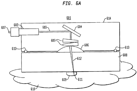
Fig. 6A presents an optical scanning apparatus system or sensor system for
taking blood glucose measurements, according to an embodiment of the present
invention. Specifically, the sensor system in Fig. 6A includes a dual wedge
prism sensor
housing 614 attached to a disposable optical lens apparatus 608 with a Petzval
surface
609. In Fig. 6A, sensor system 601 comprises a sensor housing 614 that
includes a
collimator 602 connected to a light source at a connecter 607, wherein the
light source
produces a collimated light 603. An example of a connecter is a fiber-optic
cable. The
collimated light 603 hits a fixed mirror 604, which bends the collimated light
603 to a
ninety degree angle. The collimated light 603 passes through rotating dual
wedge
prisms 605 that deviate the angle of collimated light 603 off the optical axis
of the
sensor 601. The amount of deviation is based on the thickness of each wedge
prism 605
that the collimated light 603 passes through as the wedge prisms 605 rotate.
The
collimated light 603 then passes through a focusing lens 606, which combines
the
collimated light 603 into converged light 612, and facilitates focusing the
converged
light 612 to the focal plane and focal point 611. The converged light 612 then
passes
through a disposable optical apparatus 608. The disposable apparatus 608
provides an
interface between the sensor and the surface of the skin 610 and facilitates
setting a
distance from focusing lens 606 to the focal plane that is fixed at the skin
surface 610 by
positioning the interface of the skin surface 610 with the optical window 609
to the focal
plane. Because the focal point 611 traces out a curved path as it deviates
from the
optical axis, attached to the bottom surface of the disposable apparatus 608
is a Petzval
dome 609 that acts as an optical window and focuses the focal point 611 onto
the surface
of the skin 610. As shown in Fig. 6A, the Petzval surface 609 is a separate
component
physically attached to the bottom surface of the disposable apparatus 608.
AIternately,
the Petzval surface 609 may be integrally formed from the same material as the
disposable apparatus 608. In some instances, the focusing lens 606 can be a
portion of a
disposabie lens assembly that also includes the disposable apparatus 608 and
the optical
CA 02643776 2008-08-26
WO 2007/109147 PCT/US2007/006666
-19-
window 609 (e.g., a Petzval dome). This construction can be advantageous since
light
from a coupled scanning system requires less precise spatial control when the
light has
not been focused. Like the dome 609, the lens can either be a separate
component
attached to the apparatus 608, or could be integrally formed thereon. In other
instances,
a disposable lens apparatus does not include the focusing lens, the lens being
part of the
scanning system or some other optical component of the system that can be
coupled to
the disposable lens apparatus. A data collecting device, such as a computer
may connect
to the sensor housing 616 via the connector 602.
In Figure 6B, an interferometer, an optical receiver, a demodulator, and an
optical source may be miniaturized and coupled directly to the sensor housing
via the
connector 607, as shown at 615, making the sensor a "sample arm" of the
interferometer.
Additionally, the interferometer 615 may be connected to a computer 616 that
downloads the sensor data and manipulates the data to produce a blood level
glucose or
other physiological reading.
In Fig. 6A, the disposable optical lens apparatus 608, including the focusing
lens
606 and the Petzval surface 609, may be attached and left on the skin 610
using a topical
adhesive, such as, for example, cyanoacrylate or medical adhesive, such as 3M
Medical
Adhesive. The sensor housing 614 then attaches to the disposable apparatus 608
at
connectors 613. When a patient has completed taking a glucose reading, the
patient may
remove the sensor housing 614 and leave the disposable apparatus 608 attached
to the
skin. Thus, for the next glucose reading, which may be at some later point in
time,
perhaps after a meal, the patient need not worry about trying to place the
sensor system
601 in the same location as the previous reading in order to produce
comparable results.
Instead, the patient may merely attach the sensor housing 614 to the
disposable
apparatus 608 using connectors 613 whenever a glucose reading is desired. The
disposable apparatus 608 then may be removed and discarded at the end of a
day, for
example, and replaced with a new disposable apparatus 608 the following day.
Alternately, the patient may leave the sensor housing 614 attached to the
disposable
apparatus 608 for an extended period of time to permit continuous blood
glucose
readings.
CA 02643776 2008-08-26
WO 2007/109147 PCT/US2007/006666
-20-
Figs. 7A and 7B present disposable optical lens apparatuses, according to an
embodiment of the present invention. As shown in Fig. 7A, collimated light 603
pass
through the focusing lens 606 and combine to become converged light 612 to
pass
through the disposable optical apparatus 608. The converged light 612 focus
into focal
point 611 on the focal plane. The focal plane is captured by the dome-shaped
Petzval
surface 609 attached to the bottom surface of the disposable apparatus 608.
The Petzval
surface 609 ensures that the focal point 611 remains at the skin interface to
optimize the
amount of light entering and exiting the skin 610. Fig. 7B presents a similar
design of a
disposable optical apparatus 608, but with a pedestal-shaped optical window
609,
according to an embodiment of the present invention.
Figs. 7C and 7D present a top view and side view, respectively, of a lens
assembly according to a further embodiment of the invention. The assembly 700
includes a lens 706, an attachment fitting 701, and an optical window 709. An
assembly
body 708 can be used to mount the lens 706, attachment fitting 701, and
optical window
709. The attachment fitting 701 can be used to removeably couple the assembly
700 to
an optical system that generates light (e.g., a collimated beam) that strikes
the lens 706.
A skin contacting member 720 can act. as a patch that is adhered to the skin
using
adhesive or some other attachment mechanism. Like the devices shown in Figs.
7A and
7B, the optical window can be dome-shaped (e.g., having a Petzval surface) or
can be
pedestal shaped (e.g., having a skin contacting surface that is smaller than
the surface
which contacts the remainder of the assembly).
As described herein, various embodiments utilize an optical window with a
Petzval surface. In other words, the optical window can be designed with a
surface that
substantially traces the focal points of light beams that strike a focusing
lens from
various directions before reaching the optical window. Thus, the shape of the
Petzval
surface. depends upon the qualities of the focusing lens. In the present
application, the
term "Petzval" includes objects that are substantially Petzval-like (e.g., a
surface that is
manufactured to be a Petzval surface but can have minor imperfections from
factors
such as manufacturing tolerances or other handling defects).
In some embodiments, portions of an optical system (e.g., a lens assembly) can
be configured to enhance the power of light retumed through an optical window
after
reflection. In the following description, we discuss aspects of such
embodiments with
CA 02643776 2008-08-26
WO 2007/109147 PCT/US2007/006666
-21 -
respect to alterations of a Petzval surface though it is clear that such
aspects can also be
implemented without the use of a Petzval surface. Fig. 8A presents a lens
assembly in
which collimated light 830 passes through a focusing lens 820, and is focused
onto an
optical window surface 840. Because the collimated light 830 strikes the lens
820 away
from the central axis 821, the focused light axis 831 does not coincide with
the central
axis 820. As well, the focused light axis 831 and the tangent line 841 to the
surface 840
at their intersection point do not form a right angle. Consequently, a portion
of the light
will be reflected or refracted away from the initial light path, resulting in
a loss of light
power.
To enhance the power of a return signal by reducing the effects of angular
reflection or refraction losses, the lens, the optical window, or both
components can be
configured such that the focused light's axis is perpendicular to the tangent
of the optical
window. This is depicted in Fig. 8B. In this illustration, collimated light
835 strikes
lens 825 off the lens' optical axis 826. The focused light is directed on the
surface 845
of the optical window such that the focus light's axis 836 and the tangent to
the surface
846 forms a right angle at their intersection point. Consequently, the optical
window
surface does not cause reflection or refraction effects off angle that result
in a loss of
return light signal power.
A Petzval surface which is modified to achieve the effect described above is
known herein as a reflection-compensated Petzval surface. In general, given
the
teachings of the present application, one skilled in the art can design a lens
assembly to
achieve these effects by choosing an appropriate focal length for the system,
and
choosing the configurations of the lens and optical window accordingly. It is
also
possible, however, to design such a system given a fixed lens design, or
optical window
design, and modifying the window or lens, respectively, to achieve the
enhancement in
return light power. These alterations, among others, are contemplated to be
within the
scope of the present invention.
Fig. 9 presents an exemplary method of using the optical sensor system 601 for
blood glucose measurements. The steps of the method need not be in the
sequence
illustrated, and some steps may occur essentially simultaneously. At step
S801, a patient
may place or rub an index matching medium, such as glycerine, onto an area of
skin 610
where a blood glucose reading is to be taken. Use of an index matching medium
CA 02643776 2008-08-26
WO 2007/109147 PCT/US2007/006666
-22-
facilitates matching the indices of refraction between the material of the
Petzval surface
609 with the patient's skin 610 in order to optimize the amount of light that
enters and
exits the skin 610, and expedites the time required for the Petzval surface
609 to reach
equilibrium with the skin surface 610. For example, if the material used in
the Petzval
surface 609 has an index of refraction of 1.5 and the patient's skin 610 has
an index of
refraction of 1.3, then without an index matching medium some of the focused
converged light 612 entering the skin is lost due to the lower index of
refraction of the
skin 610. Accordingly, not all of the light exits the skin 610 due to the
lower index of
refraction, which causes a loss of data. By using an index matching medium
with, in
this example, a refractive index of 1.4, the medium provides an optical
transition for the
converged light 612 between the Petzval surface 609 and the skin 610, which
increases
the amount of light that enters and exits the skin 610. Without the index
matching
medium, a patient would have to wait upwards of 60 to 90 minutes for the skin
to
produce sweat and other skin oils at the area where the disposable is placed,
in order to
optimize the data collection of the sensor. Alternatively, or in addition, a
skin-
contacting medium can act to reduce the effects of optical surface roughness
by filling in
gaps and pores of skin or other interfaces to enhance contact between the
interfaces.
With the medium in place, at step S802, the patient may adhere the disposable
lens apparatus 608 to the area where the index matching medium was placed.
Common
adhesives such as cyanoacrylate or medical adhesive may be used to secure the
disposable apparatus 608 to the skin 610. Once the patient feels that the
disposable
apparatus 608 is secure, at step S803, the patient couples the sensor housing
614 to the
disposable apparatus 608 using the connectors 613.
At step S804, sensor diagnostics verify that a threshold trigger of 45 dB has
been
pre-set to normalize the scans and resolve for variations in the optical path
lengths of the
scans produced by the rotating wedge prisms 605 and, accordingly, the change
in the
thickness of each wedge prism 605 during the rotations. At step S805, sensor
diagnostics verify that the angular velocity of each wedge prism 605 has been
pre-set to
a value such that the lateral position of each focused scan spot moves less
than l OX the
diameter of the focused scan spot during the data acquisition of the depth
scan. For
example, if focused scan spot size has a diameter of 20 microns, then the
angular
velocity is set to a value such that the focused beam 611 does not move
laterally more
CA 02643776 2008-08-26
WO 2007/109147 PCT/US2007/006666
- 23 =
than 200 microns during the depth scan. By setting the angular velocity of
each wedge
prism 605 to such a value, the distortion in the depth scale of each scan
produced by the
change in thickness of the wedge prism 605 as it rotates is minimized. The
threshold
trigger, depth scan rate and angular velocities are presets that may be
optimized and built
into the sensor system 601.
At step S806, the patient sets the sensor system 601 to begin scanning the
skin
610. Since a threshold trigger was set at 45 dB in step S804, the sensor
system 601 will
not accumulate scan data until the intensity of the optical signal produced by
the sensor
system 601 reaches a value of 45 dB. Preferably, the threshold is above the
highest
noise peak produced by the signal but at least 10 dB lower than the intensity
peak at the
interface between the skin 610 and the disposable apparatus 614.
Once the sensor system 601 has completed taking multiple scans, preferably
around 1500 scans, at step S807, the sensor housing 614 may be removed from
the
disposable apparatus 608, or, alternately, the sensor housing 614 may remain
and begin
to take another glucose reading. The disposable apparatus 608 remains adhered
to the
patient's skin 610. The scan datathen is manipulated by computer 616 connected
to the
interferometer 615. Because the threshold trigger was used, all the scans
taken begin at
a signal intensity of 45 dB, which is equivalent to Time 0, and accordingly,
at step S808,
the scans are averaged to reduce the speckle associated with the sensor 601.
At step
S809, the averaged scan data is manipulated using algorithms, such as those
described in
U.S. Provisional Applications Nos. 60/671,007 and 60/671,285, to derive blood
glucose
levels. At any later time, such as after a meal, the patient may reattach the
sensor
housing 614 to the disposable apparatus 608 to take another glucose
measurement.
Alternately, the sensor system 601 may be designed to not use a threshold
trigger
setting at S804, and may normalize the scans once the data has been acquired.
For
example, once the sensor completes a glucose reading at step S807, computer
616 of the
sensor system 601 may apply a peak locating algorithm such as, for example,
Gaussian
peak fitting, to the first scan to locate the first peak, at step S810. Once
step S810 has
been completed, the peak locating algorithm is applied to each successive
scan, as
shown at step S81 1. At step S812, the successive scans are normalized in
depth against
the first scan by essentially designating the location of each peak as at Time
0, in order
CA 02643776 2008-08-26
WO 2007/109147 PCT/US2007/006666
-24-
to average the scans together. Thus, any distortion in the optical path length
due to the
change in the thickness of the wedge prisms 605 as they rotate is removed.
Fig. 10 presents an exemplary method for stabilizing the scan pattern of
sensor
601 and is discussed in conjunction with Fig. 10A, which is a graphical
illustration of
varying the angular velocities of the dual wedge prisms 605 of sensor system
601.
When using the sensor system 601 to take a blood glucose measurement, the
first wedge
prism 605 begins rotating at a rate of 2.1 revolutions per second ("rps"),
which is
equivalent to 2,1 Hz, at step S901, as shown at 1001 in Fig. 10A. Similarly,
at step
S902, the second wedge prism 605 begins rotating at a rate of 1.3 Hz, as shown
at 1002,
where 2.1 Hz and 1.3 Hz are not integrals of each other. The sensor system 601
then
begins to perform depth scans at a rate of 30 Hz, at step S903. An integral of
30 Hz is 2
Hz (i.e., 2 multiplied by 15 equals 30). Additionally, another integral of 30
Hz is 1.5 Hz
(i.e., 1.5 multiplied by 20 equals 30 Hz). Thus, although the wedge prisms 605
begin to
rotate at rates that are non-integrals of 30 Hz, if the angular velocities
1001, 1002 of
both wedge prisms 605 remain at 2.1 Hz and 1.3 Hz, the angular velocities may
drift
towards 2.0 Hz and 1.5 Hz, thereby becoming integrals of 30 Hz, and preventing
conformal coverage of the scan pattem area of the skin 610.
To prevent the angular velocities from becoming integrals of the depth scan
rate
and remaining at the integral rates, both angular velocities 1001 and 1002 of
the wedge
prisms 605 are varied over time, in relation to the depth scan rate and in
relation to each
wedge prism 605, as shown in Fig. 11 A. At step S904, the angular velocity
1001 of the
first wedge prism 605 is varied as the sensor system 601 continues to perform
depth
scans. In Fig. 11 A, the angular velocity 1001 of the first wedge prism 605 is
sinusoidal,
oscillating from 2.5 Hz to 1.7 Hz, over a period of 6500 milliseconds, or 6.5
seconds. At
step S905, the angular velocity 1002 of the second wedge prism 605 is varied
independent of the angular velocity 1001 of the first wedge prism 605, as
shown in Fig.
11A. In Fig. 11A, the angular velocity 1002 of the second wedge prism 605 is
sinusoidal, oscillating from 1.55 Hz to 1.1 Hz, over a period of 5250
milliseconds, or
5.25 seconds. Thus, although the angular velocities of both wedge prisms 605
may hit a
harmonic of 30 Hz during the variation, the angular velocities only remain an
integral of
30 rpm for one or two depth scans before the velocities change, thereby
minimizing the
loss of depth scan data due to the angular velocities being integrals of the
depth scan
CA 02643776 2008-08-26
WO 2007/109147 PCT/US2007/006666
- 25 -
rate. The result is a random, conformal mapping of the scanned surface area of
the skin
610 with minimal overlapping within the results, as shown at step S906.
Fig. 11 B illustrates the results of varying the angular velocities of the
wedge
prisms 605 over time with respect the depth scan rate of sensor system 601 and
with
respect to each wedge prism 605. By minimizing the potential for a harmonic
phase to
be created between the depth scan rate and the angular velocities of the wedge
prisms
605, conformal coverage of the area of skin 610 scanned is optimized, with
each dot
representing a position of an individual depth scan on the skin 610.
While the present invention has been described with respect to what is
presently
considered to be the preferred embodiments, it is to be understood that the
invention is
not limited to the disclosed embodiments. To the contrary, the invention is
intended to
cover various modifications and equivalent arrangements included within the
spirit and
scope of the appended claims. The scope of the following claims is to be
accorded the
broadest interpretation so as to encompass all such modifications and
equivalent
structures and functions.