Language selection

Search

Patent 2643965 Summary

Third-party information liability

Some of the information on this Web page has been provided by external sources. The Government of Canada is not responsible for the accuracy, reliability or currency of the information supplied by external sources. Users wishing to rely upon this information should consult directly with the source of the information. Content provided by external sources is not subject to official languages, privacy and accessibility requirements.

Claims and Abstract availability

Any discrepancies in the text and image of the Claims and Abstract are due to differing posting times. Text of the Claims and Abstract are posted:

  • At the time the application is open to public inspection;
  • At the time of issue of the patent (grant).
(12) Patent: (11) CA 2643965
(54) English Title: APPARATUS FOR GUIDING A STRIP
(54) French Title: DISPOSITIF ET PROCEDE POUR GUIDER UNE BANDE
Status: Deemed expired
Bibliographic Data
(51) International Patent Classification (IPC):
  • B21B 38/08 (2006.01)
  • B22D 11/12 (2006.01)
(72) Inventors :
  • GIRGENSOHN, ALBRECHT (Germany)
  • RUNGE, ANDREAS (Germany)
(73) Owners :
  • SMS SIEMAG AKTIENGESELLSCHAFT (Germany)
(71) Applicants :
  • SMS DEMAG AG (Germany)
(74) Agent: RICHES, MCKENZIE & HERBERT LLP
(74) Associate agent:
(45) Issued: 2012-07-10
(86) PCT Filing Date: 2007-05-30
(87) Open to Public Inspection: 2007-12-13
Examination requested: 2010-04-14
Availability of licence: N/A
(25) Language of filing: English

Patent Cooperation Treaty (PCT): Yes
(86) PCT Filing Number: PCT/EP2007/004753
(87) International Publication Number: WO2007/140903
(85) National Entry: 2008-08-27

(30) Application Priority Data:
Application No. Country/Territory Date
10 2006 027 066.5 Germany 2006-06-10

Abstracts

English Abstract


The invention concerns a device for guiding a strip,
especially a metal strip, by means of one or more rolls. In
this regard, the roll force that acts on the rolls during the
guidance of the strip, i.e., under load, is measured.

Devices of this type are known in the prior art, e.g.,
from European Patent EP 0 539 784 22, which discloses a
continuous casting plant in which the rolls of a strand guide
apparatus are adjusted by means of hydraulic cylinders. To
measure the mechanical loads that act on the individual rolls
of the strand guide apparatus during its operation, a load
cell or force gauge is assigned to each roll. In this regard,
the load cell is mounted between the bearing block in which
the roll is supported and a segmented crosshead.

Moreover, the following documents disclose prior-art
devices of the aforementioned type:

-- DE 41 21 116 A1,
-- "Sensitive measurement of roll separation forces",
Steel Times International, DMG World Media, Lewes, GB, Vol.


French Abstract

L'invention concerne un dispositif et un procédé pour guider une bande, notamment une bande métallique. Les dispositifs connus de ce type présentent un dispositif de support (110), sur lequel sont fixés des coussinets (120). Dans les coussinets sont montés des rouleaux (130) pouvant tourner, afin de guider la bande. Afin de pouvoir mesurer de manière durable et fiable la force du rouleau agissant en charge, c'est-à-dire lors du guidage de la bande sur le rouleau, la déformation du coussinet, notamment en cas de charge, est détectée selon l'invention avec un dispositif de capteur puis on calcule à l'aide d'un dispositif d'analyse la force de rouleau recherchée à partir de la déformation du coussinet.

Claims

Note: Claims are shown in the official language in which they were submitted.


We claim:

1. A device (100) for guiding a strip (200), which
comprises:

-- at least one bearing block (120);

-- a roll (130) that is rotatably supported in the one
or more bearing blocks and guides the strip (200); and

-- a measuring apparatus (140) for detecting the roll
force that acts on the roll during the guidance of the
strip; where the measuring apparatus (140) comprises:

-- a sensor unit (142) for detecting the deformation
of the bearing block (120) during the guidance of the
strip (200) ; and

-- an evaluation unit (144) for computing the roll
force that acts on the roll (130) from the deformation of
the bearing block detected by the sensor unit (142),
wherein the bearing block (120), whose deformation is
being measured, has a cavity (122) or a recess for
holding at least one of the sensor unit (142) and the
evaluation unit (144).

2. A device (100) in accordance with Claim 1,
wherein the sensor unit (142) is designed in the form of an
ultrasonic sensor, an eddy-current sensor, a fiber-optic
gap sensor, or a test probe.

3. A device (100) in accordance with Claim 1 or
9


Claim 2, wherein the bearing block (120), whose deformation
is to be measured, has a suitable weak point (124), whose
own deformation during the guidance of the strip (200) can
be detected by the sensor unit (142) as representative of
the deformation of the bearing block (120).

4. A device (100) in accordance with Claim 3, wherein
the weak point (124) is designed as a slot, which is
arranged in such a way in the bearing block (120), that it
deforms during the guidance of the strip.

5. A device as claimed in Claim 4, wherein the slot
is arranged in the vicinity of a bore (126) for holding the
roll neck.

6. A device (100) in accordance with any one of
Claims 2 to 5, wherein the sensor device (142) comprises a
gap sensor suitably arranged for detecting deformation of
the slot during the guidance of the strip.

7. A device (100) in accordance with any one of
Claims 1 to 6, wherein the bearing block is mounted on a
support apparatus (110), the device (100) is designed as a
strand guide apparatus, the support apparatus (110) is
designed as a segmented frame, and the roll (136) is
designed as a segmented roll for guiding the strip in the
form of a slab, from an upstream casting installation.

8. A device (100) in accordance with any one of
Claims 1 to 6, wherein the bearing block is mounted on a


support apparatus (110), the device (100) is designed as a
rolling stand, the support apparatus (110) is designed as a
housing, and the roll (136) is designed as a work roll or
back-up roll for guiding and rolling the strip (200).

9. A device (100) in accordance with any one of
Claims 1 to 6, wherein the device (100) is designed as a
looper for the temporary storage of parts of the strip
(200).

10. A device as claimed in any one of Claims 1 to 6,
8 or 9 wherein the strip comprises a steel strip.

11. A device (100) for guiding a metal strip (200),
which comprises:

at least one bearing block (120);

a roll (130) that is rotatably supported in the one or
more bearing blocks and guides the strip (200); and

a measuring apparatus (140) for detecting the roll force
that acts on the roll during the guidance of the strip; where
the measuring apparatus (140) comprises:

a sensor unit (142) for detecting the deformation of the
bearing block (120) during the guidance of the strip (200);
and

an evaluation unit (144) for computing the roll force
that acts on the roll (130) from the deformation of the
bearing block detected by the sensor unit (142),

wherein the bearing block (120), whose deformation is
11


being measured, has a cavity (122) or a recess, at least one
of the sensor unit (142) and the evaluation unit (144) being
mounted in the cavity.

12. A device (100) in accordance with Claim 11, wherein
the sensor unit (142) is designed in the form of an ultrasonic
sensor, an eddy-current sensor, a fiber-optic gap sensor, or a
test probe.

13. A device (100) in accordance with Claim 11, wherein
the bearing block (120), whose deformation is to be measured,
has a suitable weak point (124), whose own deformation during
the guidance of the strip (200) can be detected by the sensor
unit (142) as representative of the deformation of the bearing
block (120).

14. A device (100) in accordance with Claim 13, wherein
the weak point (124) is designed as a slot, which is arranged
in such a way in the bearing block (120), in the vicinity of a
bore (126) for holding the roll neck, that it deforms during
the guidance of the strip.

15. A device (100) in accordance with Claim 14, wherein
the sensor unit is a gap sensor (142) arranged for detecting
deformation of the slot during the guidance of the strip.

16. A device (100) in accordance with Claim 11, wherein
the bearing block is mounted on a support apparatus (110), the
device (100) is designed as a strand guide apparatus, the

support apparatus (110) is designed as a segmented frame, and
12


the roll (136) is designed as a segmented roll for guiding the
strip in the form of a slab, from an upstream casting
installation.

17. A device (100) in accordance with Claim 11, wherein
the bearing block is mounted on a support apparatus (110), the
device (100) is designed as a rolling stand, the support

apparatus (110) is designed as a housing, and the roll (136)
is designed as a work roll or back-up roll for guiding and
rolling the strip (200) in the form of a metal strip.

18. A device (100) in accordance with Claim 11, wherein
the device (100) is designed as a looper for the temporary
storage of parts of the strip (200).

19. A device in accordance with any one of claims 11 to
15, 17 or 18 wherein the strip comprises a steel strip.

13

Description

Note: Descriptions are shown in the official language in which they were submitted.


CA 02643965 2008-08-27
APPARATUS FOR GUIDING A STRIP

The invention concerns a device for guiding a strip,
especially a metal strip, by means of one or more rolls. In
this regard, the roll force that acts on the rolls during the
guidance of the strip, i.e., under load, is measured.

Devices of this type are known in the prior art, e.g.,
from European Patent EP 0 539 784 22, which discloses a
continuous casting plant in which the rolls of a strand guide
apparatus are adjusted by means of hydraulic cylinders. To
measure the mechanical loads that act on the individual rolls
of the strand guide apparatus during its operation, a load
cell or force gauge is assigned to each roll. In this regard,
the load cell is mounted between the bearing block in which
the roll is supported and a segmented crosshead.

Moreover, the following documents disclose prior-art
devices of the aforementioned type:

DE 41 21 116 Al,

"Sensitive measurement of roll separation forces",
Steel Times International, DMG World Media, Lewes, GB, Vol.
1


CA 02643965 2008-08-27

14, No. 4, July 1, 1990, p. 31, XP000161372; ISSN: 0143-7798,
-- US 2,050,106 A, and

-- DE 34 22 766 Al.

In practical terms, all of these documents disclose a device
for guiding a metal strip with a bearing block, in which a
roll for guiding the strip is rotatably supported. In
addition, the device comprises a sensor unit for detecting
deformation of the bearing block during the guidance of the
strip and an evaluation unit for computing the roll force that
acts on the roll from the deformation of the bearing block
that is detected by the sensor unit.

Proceeding from this prior art, the objective of the
invention is to further develop a known device for guiding a
metal strip in such a way that, on the one hand, the sensor
unit and/or the evaluation unit are located spatially close to
the location of the deformation that is to be measured and
that, on the other hand, they are protected from environmental
influences.

This objective is achieved by the object of device Claim
1. In practical terms, in accordance with the invention, the
bearing block, whose deformation is being measured, has a

cavity or a recess for holding the sensor unit and/or the
2


CA 02643965 2008-08-27
evaluation unit.

The cavity in the bearing block offers the advantage that
when the sensor unit and/or the evaluation unit is mounted in
the cavity, on the one hand, it is then located spatially

close to the location of the deformation of the bearing block
that is to be measured and, on the other hand, it is protected
there in the bearing block from environmental influences,

especially moisture.

The term "strip" is used very broadly in the context of
the invention. It basically means strips of any material and
any cross section, including cables and threads. However, the
term especially means metal strips, including, specifically,
slabs.

The term "roll" is also used very broadly in the context
of the invention. In principle, therefore, rolls may also be
wheels or guide pulleys. However, the term is applied here
especially to a strand guide roll of a strand guide apparatus,
a roll of a rolling stand, or a roll of a looper or other
device for the temporary storage of metal strip.

The claimed indirect method for measuring the roll force
offers the advantage that it is very easily installed and
yields reliable measurement results for the roll forces for an

3


CA 02643965 2008-08-27
extended period of time.

A design of the sensor unit in the form of an ultrasonic
sensor, an eddy-current sensor, or an optical gap sensor
offers the advantageous possibility of contactless measurement
of the deformation, which requires only minor design measures
on the bearing block.

If the bearing block has a suitable weak point, it is
advantageous if its deformation during the guidance of the
strip can be easily detected by the sensor unit as

representative of the deformation of the bearing block.

It is especially simple to design the weak point in the
form of a slot. It is then advantageous for the sensor unit
to be designed as a simple and inexpensive gap sensor, which
then detects the deformation of the bearing block under load
in the form of constriction of the slot.

Advantageous embodiments of the device are objects of the
dependent claims.

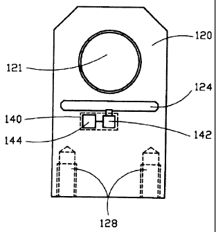
The specification is accompanied by three figures.

-- Figure 1 shows a device for guiding a metal strip.
-- Figure 2 shows a bearing block of the device in the
unloaded state.

4


CA 02643965 2008-08-27

-- Figure 3A shows a bearing block in the unloaded state.
-- Figure 3B shows the bearing block in the loaded state.
The invention is described in detail below with reference

to the specific embodiments illustrated in the drawings. In
all of the figures, elements that are the same are identified
by the same reference numbers.

Figure 1 shows a merely exemplary device 100 of the
invention in the form of a strand guide apparatus. In the
case illustrated here, it serves to guide a strip 200 in the
form of a metal strip, especially a slab. The support
apparatus 110 for this device 100 is designed as a segmented
frame. Bearing blocks 120 for holding rolls 130 are mounted
on the segmented frame or on its crossheads. In the strand
guide apparatus shown in Figure 1, two rolls 130 are mounted
opposite each other to form a roll gap, in which the metal
strip 200 is guided.

Figure 2 shows a cross section through a bearing block
120. A bore 121 is formed in the bearing block 120 for
supporting the rolls 130 by holding their necks. The bearing
block 120 is mounted on the support apparatus 110 with bolted
connections 128. The bearing block 120 has an artificial weak
point 124 in the form of a slot. Figure 2 also shows a


CA 02643965 2008-08-27

measuring apparatus 140, which comprises a sensor unit 142 and
an associated evaluation unit 144. The sensor unit 142
detects the deformation of the bearing block under load, i.e.,
during the guidance of the strip 200. The. evaluation unit 144
computes the roll force that is sought, i.e., the force that
acts on the roll 130 under load. The evaluation unit 144
calculates this roll force from the deformation of the bearing
block that is detected by the sensor unit 142.

Figures 3A and 3B show a comparison of the bearing block
in the unloaded state (Figure 3A) and in the loaded state
(Figure 3B). Figure 3B clearly shows the deformations,
especially compression, of the bearing block that results from
the load F. The measuring apparatus 142 is designed as a gap
sensor for the embodiments shown in Figures 2 and 3. It
detects, preferably continuously, constriction of the slot 124
under load compared to the larger slot that is present in the
unloaded state. The detected constriction of the slot 124
represents the deformation of the bearing block 120 under
load. The mathematical relationship between the gap
measurement signal of the gap sensor and the forces acting on
the roll is determined by the characteristic of the measuring
sensor and the exact geometry of the bearing block. A simple

6


CA 02643965 2008-08-27

linear or almost linear relationship with polynomial
components is obtained, so that the forces that are acting can
be computed in a simple way from the measured deformations.

The evaluation unit 144 then uses this deformation to
compute the sought force F acting on the roll under load.
Figure 3B shows an example of the bearing block under

load, with the deformation shown highly exaggerated. For
example, the deformation of the bearing block in the vicinity
of the weak point or the slot in a strand guide apparatus with
the maximum permissible roll '_oad is only 0.02 to 0.3 mm.

Geometric variations of this magnitude can be measured without
any problem and in this respect allow a sufficiently large
measurement signal that represents the deformation of the
bearing block.

In this regard, however, it is necessary to consider that
the geometric variations of the specified order of magnitude
occur only in the area of the artificially incorporated weak
point; otherwise, the deformations are typically of a much
smaller order of magnitude that are barely still measurable.
In this respect, the weak point offers a suitable means of
transforming the deformation of the bearing block to a
magnitude that can be measured or of rendering the deformation

7


CA 02643965 2008-08-27

visible. On the one hand, the weak point must be suitably
designed for this purpose. On the other hand, however, it is
also necessary to guarantee that the bearing block 120 is not
weakened to an unacceptable degree by the weak point, but

rather, e.g., in the case of an embodiment of the device as a
strand guide apparatus, to guarantee that the deformation of
the weak point remains so small that the strand shell of a
slab is not subjected to an overload due to the change in the
roll position under load.

8

Representative Drawing
A single figure which represents the drawing illustrating the invention.
Administrative Status

For a clearer understanding of the status of the application/patent presented on this page, the site Disclaimer , as well as the definitions for Patent , Administrative Status , Maintenance Fee  and Payment History  should be consulted.

Administrative Status

Title Date
Forecasted Issue Date 2012-07-10
(86) PCT Filing Date 2007-05-30
(87) PCT Publication Date 2007-12-13
(85) National Entry 2008-08-27
Examination Requested 2010-04-14
(45) Issued 2012-07-10
Deemed Expired 2017-05-30

Abandonment History

There is no abandonment history.

Payment History

Fee Type Anniversary Year Due Date Amount Paid Paid Date
Application Fee $400.00 2008-08-27
Maintenance Fee - Application - New Act 2 2009-06-01 $100.00 2008-08-27
Registration of a document - section 124 $100.00 2008-11-10
Registration of a document - section 124 $100.00 2009-07-03
Request for Examination $800.00 2010-04-14
Maintenance Fee - Application - New Act 3 2010-05-31 $100.00 2010-04-29
Maintenance Fee - Application - New Act 4 2011-05-30 $100.00 2011-04-27
Final Fee $300.00 2012-03-23
Maintenance Fee - Application - New Act 5 2012-05-30 $200.00 2012-04-23
Maintenance Fee - Patent - New Act 6 2013-05-30 $200.00 2013-05-21
Maintenance Fee - Patent - New Act 7 2014-05-30 $200.00 2014-05-19
Maintenance Fee - Patent - New Act 8 2015-06-01 $200.00 2015-05-19
Owners on Record

Note: Records showing the ownership history in alphabetical order.

Current Owners on Record
SMS SIEMAG AKTIENGESELLSCHAFT
Past Owners on Record
GIRGENSOHN, ALBRECHT
RUNGE, ANDREAS
SMS DEMAG AG
Past Owners that do not appear in the "Owners on Record" listing will appear in other documentation within the application.
Documents

To view selected files, please enter reCAPTCHA code :


To view images, click a link in the Document Description column. To download the documents, select one or more checkboxes in the first column and then click the "Download Selected in PDF format (Zip Archive)" or the "Download Selected as Single PDF" button.

List of published and non-published patent-specific documents on the CPD .

If you have any difficulty accessing content, you can call the Client Service Centre at 1-866-997-1936 or send them an e-mail at CIPO Client Service Centre.


Document
Description 
Date
(yyyy-mm-dd) 
Number of pages   Size of Image (KB) 
Abstract 2008-08-27 1 24
Claims 2008-08-27 3 72
Drawings 2008-08-27 2 25
Representative Drawing 2008-08-27 1 6
Cover Page 2009-01-12 2 42
Claims 2011-10-25 5 143
Description 2008-08-27 8 219
Abstract 2012-06-18 1 24
Representative Drawing 2012-06-21 1 7
Cover Page 2012-06-21 2 46
Assignment 2008-08-27 4 124
PCT 2008-08-27 14 539
Assignment 2008-11-10 3 89
Prosecution-Amendment 2008-08-28 1 35
PCT 2008-08-28 5 149
Assignment 2009-07-03 20 932
Prosecution-Amendment 2010-04-14 1 49
Prosecution-Amendment 2011-09-19 2 43
Prosecution-Amendment 2011-10-25 13 394
Correspondence 2012-03-23 1 55