Note: Descriptions are shown in the official language in which they were submitted.
CA 02644043 2008-08-25
WO 2007/100674 PCT/US2007/004751
SYSTEM AND METHOD FOR MIXING DISTINCT AIR STREAMS
BACKGROUND OF THE INVENTION
=
1. Field of the Invention
[0001] The present invention relates generally to the field of fluid dynamics
and heat
transfer, and more specifically to a system and method for mixing fluid
streams within an
industrial drying machine.
2. Description of the Prior Art
=
[0002] Industrial machines, such as those common in the textile, nonwovens and
paper manufacturing industries, commonly utilize heated air to dry a newly
formed product,
as well for thermal bonding, curing and other processes that require an air
stream with a
uniform temperature profile. Typically, air is heated through conventional
combustion means
and then directed in various fashions towards the web of wet material. The
heated air
passes through or impinges the web, losing some of its heat in the drying
process. The
cooled air, referred to as system air, is then divided into portions that are
re-circulated
through the drying machine and portions that are exhausted into the
atmosphere.
[0003] Drying machines in the aforementioned industries are generally of three
types: through-air-dryers (TAD), impingement dryers, or floatation dryers.
Each of these
types of dryers is typically contained within a drying hood, which supplies
and directs heated
air to the surface of the web. A vacuum or pressure differential pulls the
heated air through
or onto the surface of the web and exhausts the cooled air into the system at
large, at which
point a portion of the cooled air will be exhausted into the atmosphere while
the remainder is
reused for drying applications. The direction of. travel of the web is
referred to as the
Machine direction, and the direction perpendicular to the machine direction
and coplanar
with the web is referred to as the cross-machine direction.
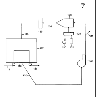
[0004] A typical dryer system 100 is shown in Figure 1. As noted, the system
100
includes a dryer 110 that is partially surrounded by a dryer hood 112, through
which air is
drawn from the surrounding structures. A web of goods enters the hood 110 on
the wet end
114 and proceeds through the dryer 110, where heated air is drawn through it,
to the dry end
116. The heated air is pushed in through an intake 118 and is drawn out of an
exhaust 120
1
CA 02644043 2008-08-25
WO 2007/100674 PCT/US2007/004751
by a main fan 122 which drives partially closed circuit as shown in Figure 1.
A portion of the
system air is exhausted into the atmosphere through duct 124.
[0005] The remaining system air is directed to an air heater 126 that combines
the
system air with combustion products from a burner 128. The burner 128 is
driven by a
combustion air source 130, such as a fan, and fuel 132. The mixed air 134 is a
combination
of combustion products and system air that will be used to dry the web passing
through the
dryer hood 112. Those skilled in the art will recognize that the combination
of the system air
and the combustion products will not necessarily produce a uniformly profiled
stream of
heated air. On the contrary, the introduction of a secondary stream of
combustion products
into the system air may produce non-homogenous profile for the mixed air 134.
As a result,
a typical dryer system 100 generally incorporates a static mixer 136 for
inducing turbulence
and mixing into the mixed air 134 stream so as to maximize thermal uniformity
prior to
entering the drying hood.
[0006] The foregoing example demonstrates both the strengths and weaknesses of
the state of the art heating systems. While the current art is able to make
remarkable use of
system air through the re-circulation mechanisms, the necessary mixing of that
air with
combustion products is potentially hazardous to the end product. An essential
aspect of
textile and paper manufacturing is that the air that is drawn through or
impinged upon the
product must have a substantially uniform temperature profile along the cross-
machine
direction. Particularly for the manufacture of lightweight materials, such as
tissue paper, any
deviation in the temperature profile can irreversibly damage the finished
product. The
economic effects of non-uniform heating are multiple, including the energy
required to
replace the lost product, the costs of replacing the wasted raw materials, and
the labor
necessary to fix, maintain, manage and operate the dryer through a new
production cycle.
As such, one of the paramount concerns in the paper industry is designing a
dryer that
reliably maintains a uniform temperature profile in the cross-machine
direction.
[0007] As noted above, it is common practice to re-circulate spent system air
and
reuse it in the drying cycle. Typically, the system air is combined with newly
heated air and
then the air is mixed as it passes through the machine ductwork towards the
web of goods.
Although the industry has made several attempts at efficiently re-circulating
the air
exhausted through the roll, the current state of the art requires a
significant distance
between the mixing point and the web in order to ensure that the temperature
profile of the
mixed stream is sufficiently homogenous.
2
CA 02644043 2008-08-25
WO 2007/100674 PCT/US2007/004751
[0008] For example, attempts have been made to introduce a heated fluid stream
into a cooler fluid stream by using a baffling structure. Such a mechanism was
contemplated in the invention described in international publication
WO/0012202 published
on March 9, 2000. Although that invention describes a mechanical means for
inducing
turbulence, and hence mixing, in the combination of two fluid streams, it
still does not do so
with optimal efficiency of space and energy. In particular, the baffle design
does create a
large eddy that induces mixing of the fluid streams, but it does not do so in
a symmetrical or
uniform manner. Thus, the designers must either remix the turbulent air with a
second
device such as a static mixer; or alternatively, they must maximize the
distance between the
baffle location and the intake into the drying hood. Each of these two
solutions involves non-
trivial modifications to the drying systems described above, and both
solutions would cost
the producer in terms of energy efficiency and space utilization.
[0009] Given the foregoing, it is readily apparent to those skilled in the art
that there
is a need for a system and method for mixing fluid streams that is compact,
energy efficient
and produces a reliably uniform temperature profile across the web. Moreover,
there is a
need in the art for solutions that can be easily integrated into current
drying system design
without greatly expanding the hardware and space necessary to manufacture
textiles.
Lastly, there is a need in the art for a drying system that will minimize
energy expenditures
while deriving the greatest benefits from the raw materials processed therein.
SUMMARY OF THE INVENTION
[0010] Accordingly, the present invention relates to a novel drying system
that
incorporates two-stage processes for heating air for drying a traveling web.
In its various
embodiments, the present invention operates within a system having a drying
hood
containing a dryer. The drying hood receives heated air through an intake and
expels
system air through an exhaust, a portion of which is directed into the
atmosphere. In one
embodiment, the portion of system air that is maintained in the system is
divided into two
portions and directed into separate parallel loops for two-stage heating that
results in greater
temperature uniformity and efficiency within the drying system.
[0011] The first portion of the system air is directed into a first conduit,
and the
second portion of the system air is directed into a second conduit. The first
conduit includes
an injection chamber that is disposed serially, or incorporated into, the
drying hood intake.
The second conduit includes a mixing chamber that is coupled to a burner for
heating the air
within the system.
=
3
CA 02644043 2013-03-26
WO 2007/100674 PCT/US2007/004751
[0012] The mixing chamber includes an arrangement of passages that effectively
and efficiently mix the second portion of the system air with the combustion
products from
the burner. This mixed air stream is directed towards the injection chamber,
where an
injector or series of injectors induce further mixing by injecting the mixed
air stream into the
first portion of the system air. The injection chamber can also be integrated
into the drying
hood and controlled in such a manner so as to provide homogenous or non-
homogenous air
temperature across the running web, as determined by the user and the
particular drying
application.
[0013] By dividing the heating process into two stages, the present invention
greatly
increases the drying efficiency of a drying system. Notably, although one
embodiment of the
present invention utilizes a pair of distinct conduits for the heating
process, the physical size
of the drying system will not be affected. On the contrary, because of the
increased mixing
and heating efficiency of the present invention, it is possible to construct a
drying system that
is both smaller in size and more energy efficient that those presently used in
the industry.
Moreover, as described further below, the two-stage process of the present
invention can
also be utilized in a single conduit dryer configuration, in which the
injection chamber is used
for injecting an external source of heated air into the stream of mixed air
from the mixing
chamber. Numerous sources of external heated air, described below, can be
utilized for
improving the performance and efficiency of industrial dryers.
4
CA 02644043 2013-03-26
[0013a] The present invention further provides a system for drying a traveling
web of goods comprising:
a) a dryer receiving air through an intake and expelling system air through an
exhaust;
b) a single air conduit in circuitous communication with the exhaust and the
intake, the air conduit receiving the system air and directing it to the
intake;
c) an injection chamber disposed in fluid communication with the single air
conduit, the injection chamber adapted for injecting a stream of hot air from
an
external heat source into the single air conduit;
d) an external heat source coupled to the injection chamber and external to
the
system; and
e) a mixing chamber disposed in fluid communication with the single air
conduit, wherein:
i) the mixing chamber receives heated air from a burner and mixes the heated
air with the system air to form mixed air,
ii) the mixing chamber includes a first passage directing combustion product
from the burner and a second passage directing the system air, the first
passage and second passage in fluid communication such that the system air
is heated by the combustion product,
iii) the mixing chamber is disposed serially relative to the injection chamber
such that air processed through the mixing chamber is directed through the
injection chamber,
iv) the injection chamber comprises a portion of the single air conduit and
one
or more injectors for injecting hot air from an external source into the
portion of
the single air conduit for mixing with the mixed air,
v) the injector comprises a projection projecting into the single air conduit
such
that the projection disrupts the airflow of the mixed air thereby creating a
uniform temperature profile of air directed into the dryer intake, and
vi) the projection is oriented substantially orthogonal to the flow of the
system
air.
4a
CA 02644043 2013-03-26
[0014] Further details and advantages of the present invention will become
readily apparent from the detailed description of the preferred embodiments
that refers
specifically to the following drawings.
BRIEF DESCRIPTION OF THE DRAWINGS
[0015] Figure 1 is a schematic representation of a through-air-dryer system
typical of the prior art.
[0016] Figure 2A is a schematic representation of a drying system in
accordance
with one embodiment of the present invention.
[0017] Figure 2B is a schematic representation of a drying system in
accordance
with another embodiment of the present invention.
4b
CA 02644043 2008-08-25
WO 2007/100674 PCT/US2007/004751
[0018] Figure 3 is a perspective view of a mixing chamber of the drying system
of the
present invention.
[0019] Figure 4 is a cross-sectional view of the mixing chamber shown in
Figure 3
along tine 5-5.
[0020] Figure 5 is a cross-sectional view of the mixing chamber shown in
Figure 3
along line 4-4.
[0021] Figure 6 is a perspective view of an injection chamber of the through-
air-dryer
system of the present invention.
[0022] Figure 7 is a partial cut-away plan view of the injection chamber shown
in
Figure 6 in accordance with one embodiment of the present invention.
[0023] Figure 8 is a partial cut-away side view of the injection chamber shown
in
Figures 6 and 7 in accordance with one embodiment of the present invention.
[0024] Figure 9 is a partial cut-away side view of the injection chamber shown
in
Figure 6 in accordance with another embodiment of the present invention.
[0025] Figure 10 is a partial cut-away plan view of the injection chamber
shown in
Figure 9.
[0026] Figure 11 is a perspective view of a partial manifold of the injection
chamber
in accordance with the present invention
[0027] Figure 12 is a cross-sectional view of the manifold of the injection
chamber in
accordance with the present invention.
[0028] Figure 13 is a schematic diagram of a dryer system having an integrated
injection chamber in accordance with one embodiment of the present invention.
[0029] Figure 14 is a partial cut-away view of a dryer hood having an
integrated
injection chamber in accordance with one embodiment of the present invention.
CA 02644043 2008-08-25
WO 2007/100674 PCT/US2007/004751
DETAILED DESCRIPTION OF THE PREFERRED EMBODIMENTS
[0030] The present invention includes both a system and method for mixing
fluid
streams, particularly those associated with contemporary drying systems. As
described
below, the present invention solves a number of problems noted in the
textiles, paper and
non-wovens industries. Most notably, the present invention includes a
significant redesign of
the drying system that efficiently utilizes system air and mixes it with
combustion products in
order to produce uniformly heated air for the web of goods. The mixing
efficiencies of the
present invention allow for a compact dryer design that is more economical in
terms of raw
materials, energy and space utilization.
[0031] Turning to Figure 2A, the system 10 for drying a textile web is shown.
As
shown, the system 10 is represented schematically, thus it should be
understood that the
novel features of the present invention are equally applicable to all types of
industrial mixers,
including at least TAD's, floatation dryers and Yankee impingement dryers, as
well as any
=
other dryer that uses heated air for. drying goods. The system 10 includes a
dryer 12
disposed within a drying hood 14. The dryer 12 is typically one of the
aforementioned dryers
commonly used for drying goods., although it should be understood that the
present invention
is operable with any and all kinds of dryers that utilize heated air. A web
enters the drying
hood 14 at a wet end 16 and exits the drying hood 14 at a dry end 18. As
discussed in detail
above, air drawn through an intake 48 passes through the dryer 12 and the
drying hood 14
and is expelled through an exhaust 20, which is in turn coupled to a pair of
parallel conduits
that embody the system 10 of the present invention.
[0032] The exhaust 20 is coupled to a first air conduit 22 in circuitous
communication
with the exhaust 20 and the intake 48 and a second air conduit 24 in
communication with the
first air conduit 22. The air expelled through the exhaust 20 is referred to
as system air, i.e.
air that is not introduced from outside the system 10. The system air (not
shown) is divided
into a first portion 32 and a second portion 34, which are directed into the
first conduit 22 and
the second conduit 24, respectively.
[0033] A first fan 26 is part of the first air conduit 22 for receiving the
first portion 32
of the system air and directing it through an injection chamber 46. A second
fan 28 is part of
the second air conduit 24 for receiving the second portion 34 of system air
and directing it
through to a mixing chamber 36. An exhaust port 30 is preferably disposed in
the second
conduit 24 for optionally expelling some of the second portion 34 of the
system air into the
atmosphere.
6
CA 02644043 2008-08-25
WO 2007/100674 PCT/US2007/004751
[0034] The mixing chamber 36 is adapted for receiving the second portion 34 of
the
system air and mixing it into combustion products 40 emanating from a burner
38, which is
fed by a source of combustion air 41 and fuel 42. The combustion products 40
are too hot for
direct introduction into the system 10. For example, the combustion products
40 may
typically be between 1100 and 1550 degrees Celsius. Accordingly, the system 10
of the
present invention introduces a two stage mixing process in order to
efficiently temper the
combustion products 40 into a readily usable stream of air heated to a range
typically
between 400 to 1500 degrees Celsius, i.e. a stream of mixed air 44.
[0035] The resulting mixed air 44 is directed towards the injection chamber
46,
where it is injected back into the first portion 32 of the system air. After
injection of the mixed
air 44 into the first portion 32 of the system air, the intake 48 of the
system 10 directs the
uniformly profiled air into the dryer hood 14. The specific means for mixing
and means for
injection are discussed in detail below.
[0036] Figure 28 is a schematic representation of another embodiment of the
present invention, wherein identical reference numerals refer to similar
elements as
described with reference to Figure 2A. As in the previous embodiment, the
system 10
includes a dryer 12 disposed within a drying hood .14. The web enters the
drying hood 14 at
a wet end 16 and exits the drying hood 14 at a dry end 18. Air drawn through
an intake 48
passes through the dryer 12 and the drying hood 14, from whence it is expelled
through an
exhaust 20. Unlike the prior embodiment, however, that shown in Figure 2B has
a single
conduit for recycling the system air.
[0037] The exhaust 20 is coupled to a conduit 24', which is in circuitous
communication with the exhaust 20 and the intake 48. The air expelled through
the exhaust
20 is still referred to as the system air. The system air (not shown) consists
solely of a
portion 34', which is directed into the conduit 24', as noted above.
[0038] A fan 26' is part of the conduit 24' for receiving the portion 34' of
system air
and directing it through to a mixing chamber 36. An exhaust port 30 is
preferably disposed
in the conduit 24' for optionally expelling some of the portion 34' of the
system air into the
atmosphere.
[0039] As in the prior embodiment, the mixing chamber 36 is adapted for
receiving
the portion 34' of the system air and mixing it into combustion products 40
emanating from a
7
CA 02644043 2008-08-25
WO 2007/100674 PCT/US2007/004751
burner 38, which is fed by a source of combustion air 41 and fuel 42. As
previously noted,
the combustion products 40 are too hot for direct introduction into the system
10. Thus the
system 10 of the present invention introduces another two stage mixing process
in order to
efficiently temper the combustion products 40 into a readily usable stream of
air heated to a
typical range of 150 to 600 degrees Celsius referred to as the stream of mixed
air 44.
[0040] The resulting mixed air 44 is directed towards the injection chamber
46,
where it receives an injection of heated air 45 from an external source (not
shown). For
purposes of the present invention, the heated air 45 may include air that is
heated by a
turbine, a second burner, exhaust from the machinery of the system 10, as well
as certain
types of naturally occurring volumes of air, such as those derived from
geothermal
processes. Thus as defined herein, the term external source should be
understood to refer
to a source of heated air that is not derived from a burner located within the
system 10. For
example, the external source may be typified as waste heat from another
process or heat
from another, lower cost source. Accordingly, the burner 42 used in the
present invention
can be smaller and more fuel efficient, thereby reducing the overall space and
energy
consumption associated with heating the air. As in previous embodiments, after
injection of
the heated air 45 into the mixed air 44, the intake 48 of the system 10
directs the uniformly
profiled air into the dryer hood 14.
[0041] Figure 3 is a perspective view of the mixing chamber 36 of the system
10 of
the present invention. The mixing chamber 36 includes a first passage 50
directing
combustion product 40 from the burner 38, a second passage 52 carrying the
second portion
34 of the system air, and a third passage 54 directing the mixed air 44 to.
the injection
chamber 46. Preferably, the first passage 50 and second passage 52 are in
fluid
communication and oriented in an orthogonal manner, as shown in Figure 3.
[0042] Figure 4 is a cross-sectional view of the mixing chamber 36 shown in
Figure 3
along line 4-4. As shown, the mixing chamber 36 is preferably outfitted with a
perforated
sleeve 56 that selectively places air from the second portion 34 in fluid
contact with the
combustion product 40 that is traveling through the first passage 50. In the
cross-sectional
view along line 5-5 shown in Figure 5, the first passage 50 has a circular
cross-section. The
second passage 52 terminates near the intersection between it and the first
passage 50, and
the perforated sleeve 56 is disposed between the respective passages.
[0043] A volume is defined between the perforated sleeve 56 and the interior
surface
of the second passage 52, and the second portion 24 of the system air must of
course
occupy this volume as it passes through the perforated sleeve 56. In a
preferred
8
CA 02644043 2008-08-25
WO 2007/100674 PCT/US2007/004751
embodiment, the volume so defined is variable about the perforated sleeve 56,
such that the
pressure gradient along the surface of the perforated sleeve 56 will also be
variable. For
example, a volume along section 60 is greater than a volume along section 62,
which in turn
is greater than a volume along section 64. By varying the volume defining the
intersection
between the combustion product 40 and the second stream 24 of the system air,
the
designers can tailor the mixing rate of the two fluid streams as they form the
mixed air 44.
[0044] Figure 6 is a perspective view of an injection chamber 46 of the drying
system
of the present invention. The injection chamber 46 includes a third passage 70
for directing
the first portion of the system air. The third passage 70 is intersected by at
least one injector
72 that directs the mixed air 44 into the first portion of the system air. The
means for
injection are described in full detail below in conjunction with alternative
embodiments of the
system 10.
[0045] Figure 7 is a partial cut-away plan view of the injection chamber 46
shown in
Figure 6 in accordance with one embodiment of the present invention. Figure 8
is a partial
cut-away side view of the injection chamber 46. As shown in Figures 7 and 8,
an arrow
pointing leftwards represents the first portion 22 of system air. Each of the
injectors 72
includes a projection 73, which in the embodiment shown is defined by a first
tubular portion
74 and a second tubular portion 75. The injectors 72 are arranged orthogonal
to the flow of
the first portion 22 of system air, which is to say that they are also
orthogonal to the third
=
passage 70 described above.
[0046] The first tubular portion 74 and second tubular portion 75 cooperate to
define
an obtuse structure in the third passage 70 so as to create pockets of low
pressure 77 in the
flow of the first portion 22 of system air. The projections 73 defined by the
first tubular
portion 74 and second tubular portion 75 are purposefully obtuse in order to
maximize the
turbulence in the airflow and thereby induce mixing of between the mixed air
44 and the first
portion 22 of system air. A plurality of ports 78 (depicted as small arrows)
are defined on the
second tubular portion 75 for transmitting the mixed air 44 into the pockets
of low pressure
77. The flow of mixed air 44 into the third passage 70 is controlled by at
least one throttle
valve 76 disposed between each of the first tubular portions 73 and second
tubular portions
75. The throttle valves 76 are controllable by a system operator either
mechanically or
electronically, depending upon the configuration of the system 10.
[0047] Figure 9 is a partial cut-away side view of the injection chamber shown
in
Figure 6 in accordance with another embodiment of the present invention. As
shown, the
9
CA 02644043 2008-08-25
WO 2007/100674 PCT/US2007/004751
injector 80 includes a manifold 82 having a plurality of nozzles 84 disposed
thereon. Figure
is a partial cut-away plan view of the injection chamber shown in Figure 9
better
demonstrating the aerodynamic properties of the manifolds 82. Each manifold 82
defines a
leading edge 86, a central portion 88 that includes the nozzles 84, and a
trailing edge 90. As
used herein, the terms leading and trailing refer to the standard orientation
of an object in a
fluid stream, i.e. the leading edge 86 is the first edge to contact the fluid,
while the trailing
edge 90 serves to smooth out any turbulence in the fluid.
[0048] Figure 11 is a perspective view of a partial manifold 82 of the
injection
chamber 46 and Figure 12 is a cross-sectional view of the manifold 82 of the
injection
chamber 46 in accordance with the present invention. As shown, the nozzles 84
are
disposed on the surface of the central portion 88 for directing a fluid in a
direction normal to
the surface of the central portion 88. In particular, the nozzles 84 are
configured for injecting
the mixed air 44 into the first portion 22 of the system air. The aerodynamic
profile of the
manifolds 82, as detailed in Figure 12, creates small-scale turbulence in the
air stream, as
opposed to the large pressure drop described above with respect to the obtuse
projections
73. In particular, for each manifold the surface of the leading edge 86
defines an angle
relative to the central portion 88 and the trailing edge 90 defines an angle y
relative to the
central portion 88. In preferred embodiments, the leading edge 86 defines
angle 0 that is
less than twenty degrees, and is most preferably less than fifteen degrees for
optimum
aerodynamics. The trailing edge 90 defines angle y that is preferably less
than twelve
degrees, and is most preferably less than eight degrees.
[0049] As the manifolds 82 described herein are specifically designed to
reduce
turbulence in the system 10, the only turbulence created in a manifold-style
injection
chamber 46 is by the injection of the mixed air 44 into the first portion 22
of system air
through the nozzles 84. It follows that in order to maximize the mixing
activity of the two
streams, each manifold 82 must have a number of nozzles 84 disposed thereon,
preferably
arranged in multiple rows and on both surfaces of the central portion 88. As
the nozzle
velocity of each nozzle 84 can be optimized for variable conditions, a system
operator can
fine-tune the mixing performance of the injection chamber 46 for particular
needs.
[0050] One particular benefit of the manifold approach to fluid injection is
that the
temperature profile of the air entering the intake 48 can be readily
controlled using a control
loop for varying the injection rate of the manifolds 8. This increased control
over the air
profile near to or within the drying hood 14 allows for customized and
optimized temperature
CA 02644043 2008-08-25
WO 2007/100674 PCT/US2007/004751
control, which in turn permits engineers and manufacturers to develop improved
goods at
lower costs. Control over the manifolds 82 is precise enough that it is
possible to dispose
the injection chamber 46 close to, or even integrated into, the intake 48 of
the drying hood
14. In particular, electronic control over the manifolds 82 permits a
manufacturer to locate
the injection chamber 46 at any point in the system 10 that is downstream from
the mixing
chamber 36, including of course integrating the injection chamber 46 into the
drying hood 14.
[0051] By way of example, Figure 13 is a schematic diagram of a dryer system
10
having an integrated injection chamber 11 in accordance with one embodiment of
the
present invention. While similar reference numerals refer to similar elements,
the system
configuration shown in Figure 13 illustrates an injection chamber 46
integrated into the
drying hood 14. A controller 49 is coupled to the drying hood 14 and the
injection chamber
46, and is preferably configured to receive feedback signals from the drying
hood 14 in order
to monitor and adapt the nozzle velocity of the manifolds 82 of the injection
chamber 46.
The manifolds 82 of the injection chamber 46 can be controlled to create
particular
temperature profiles in the drying hood 14 in both the machine and cross-
machine
directions. Moreover, the controller 49 can be adapted to provide
instantaneous response
from the feedback signals, thus providing an effective bias against unwanted
variations in
the temperature profile of the hood.
[0052] Figure 14 is a partial cut-away view of a dryer hood 14 having an
integrated
injection chamber illustrating the precision and capabilities of the aspect of
the invention
described above. A web 19 of material is shown disposed within the hood 14.
The web 19
defines three zones of differing dryness, a first zone 190, a second zone 192
and a third
zone 194. The injection chamber 46 and intake 48 are integrated into the
drying hood 14
and disposed in close proximity to the web 19. The controller 49 receives
signals indicative
of the dryness/temperature or alternative measurement of the web, and in
response to those
signals directs the manifolds 82 within the injection chamber 46 to respond in
an appropriate
fashion.
[0053] For example, the manifolds 82 within the injection chamber 46 can be
controlled to produce three streams of differing temperature, a first stream
200, a second
stream 202 and a third stream 204. The nature of the feedback through the
controller 49
ensures that the first stream 200 corresponds to the first zone 190, the
second stream 202 to
the second zone 192, and the third stream 204 to the third zone 204.
Accordingly, the
integration of the injection chamber 46 not only provides means for
homogenizing the air
temperature within the drying hood 14, it also provides means for biasing the
air temperature
11
CA 02644043 2008-08-25
WO 2007/100674 PCT/US2007/004751
within the drying hood 14 in a manner that is readily controllable. That is,
the injection
chamber 46 can be biased to inject hot air into an area correlating with a wet
portion of the
web 19, and conversely, the injection chamber 46 can be controlled to inject
cooler air
towards a dryer portion of the web 19. In short, by integrating the injection
chamber 46 into
the drying hood 14, the present invention enables users to optimize the drying
of the web 19
in the most efficient manner.
=
[0054] The benefits of the present invention, in particular those achieved
through the
control over the manifolds 82 as well as the integration of the injection
chamber 46 into the
drying hood 14, result from the two-stage mixing processes described in detail
above, which
in turn reduces the length of the conduits necessary to direct the first
portion 22 of the
system air. Moreover, the usage of an external source, such as heated air from
an ancillary
process or machine, further lessens the costs associated with heating a
uniform stream of
air. As illustrated above, the present invention will enable engineers and
designers to
manufacture industrial dryers that utilize this process, which in turn will
increase the drying
efficiency of any number of commercial operations.
[0055] While the present invention has been described in detail with respect
to its
preferred embodiments, these should be understood to be exemplary in nature
and not
limiting as to the scope of the present invention. It is certain that design
modifications could
be readily devised by those skilled in the art, and that any such
modifications would fall
within the scope of the present invention as defined herein by the following
claims.
=
12