Note: Descriptions are shown in the official language in which they were submitted.
CA 02644288 2011-12-16
WO 2007/136903 PCT/US2007/062929
SYSTEMS AND METHODS FOR TRANSCODING BIT STREAMS
TECHNICAL FIELD
The present disclosure is generally related to the processing of bit streams,
and
more specifically to the transcoding of media bit streams.
BACKGROUND
Digital bit streams can be used for the transmission and distribution of media
signals, such as video and audio. The media streams could be, for example,
Moving
Picture Experts Group streams (i.e. MPEG-1, MPEG-2, MPEG-4 part2, MPEG-4 part
10
(i.e. H.264)), Windows Media (VC-1) streams, RealAudio streams, or MPEG Audio
Layer-3 (mp3) streams, among others that can be used for the transmission of
audio
and/or video signals in compressed digital streams. Accordingly, within the
context of
this disclosure, a multimedia stream (or simply a media stream) could comprise
one or
more of an audio stream, a video stream, or any other underlying media signals
used to
convey information (text, graphics, animation, charts, graphs, etc.).
1
CA 02644288 2008-08-29
WO 2007/136903 PCT/US2007/062929
Such multimedia streams may be transmitted over a variety of distribution
channels such as computer networks, satellite links, cable television (CATV)
lines, radio-
frequency signals, and digital subscriber lines (DSL), among others. As a
consequence,
the multimedia streams can be adapted to a particular distribution channel
over which
they may be transmitted. For example, the streams could be encoded into a
different
format e. MPEG-4 to MPEG-2), could be converted from one resolution to another
(i.e.
1280 x 720 pixels to 720 x 480 pixels), or could be converted from one bit
rate to another
(L e. 4Mbps to 2 Mbps). Such conversions of the multimedia stream, among
others, can
be collectively referred to as transcoding.
In many cases, conventional transcoders used to process a single bit stream
can be
made cost effectively and with relatively low implementation issues. However,
as the
number of media streams being transcoded increase, implementation issues
become
problematic. This is especially true in terms of the potential memory
consumption and
sheer number of processors used to perform the decoding and subsequent re-
encoding.
Accordingly, in light of these potential deficiencies, among others, it is
desirable
to provide a transcoder that is scalable to process a large number of
multimedia streams
while providing the capability to minimize the amount of processing hardware
and/or
memory.
2
CA 02644288 2008-08-29
WO 2007/136903 PCT/US2007/062929
BRIEF DESCRIPTION OF THE DRAWINGS
The components in the drawings are not necessarily to scale relative to each
other.
Like reference numerals designate corresponding parts throughout the several
views.
FIG. 1 depicts an embodiment of a cable television distribution network.
FIG. 2 depicts a schematic diagram of an embodiment of a transcoder that could
be used within the cable television distribution network of FIG. 1.
FIG. 3 is a schematic diagram of another embodiment of a transcoder that could
be
used within the cable television distribution network of FIG. 1.
FIG. 4 depicts an embodiment of a FIFO buffer arranged within the input buffer
of
FIG. 3.
FIG. 5 is a schematic diagram of another embodiment of a transcoder that could
be
used within the cable television distribution network of FIG. 1.
FIG. 6 is a schematic diagram of an embodiment of the transcoder of FIG. 5
DETAILED DESCRIPTION
Systems and methods for transcoding bit streams are disclosed. Embodiments of
the systems can be scaleable to process a large number of data streams while
conserving
memory and minimizing hardware requirements through the time sharing of
processing
and/or memory elements. An embodiment of the system includes an input buffer
for
temporarily maintaining a portion of a plurality of compressed data streams,
each portion
comprising one or more portions of an encoded signal. The system can further
include a
switch for providing selective connectivity between the input buffer and one
or more
processors.
3
CA 02644288 2008-08-29
WO 2007/136903 PCT/US2007/062929
For example, according to some embodiments, one or more processors may be
configured to analyze the one or more portions of the encoded signal in the
input buffer to
generate statistical data about the encoded signal that can be used to
transcode the bit
stream. According to some embodiments, one or more processors may be
configured to
transcode one or more portions of the encoded signal.
Although the described transcoder systems and methods could be used in a
number of potential environments, FIG. 1 depicts an embodiment of a cable
television
distribution network 100 in which embodiments of the transcoders described
herein may
be used. In general, network 100 relays multimedia signals received from a
number of
sources, such as satellites 102, to a plurality of remote locations 104. Such
multimedia
signals could be, for example video and/or audio signals, which could also be
transmitted
with additional network data, including Internet traffic, teletext, closed-
captioning, among
others. The remote locations 104 could be residences or businesses that pay
for, or
otherwise receive, cable television programming. Although reference may be
made
generally to multimedia signals throughout the detailed description, signals
having only
one form of media, such as audio or video signals alone, are intended to be
well within
the scope of the disclosure.
Such multimedia signals and/or data signals may be transmitted over a down-
link
106 from satellites 102 to a respective receiver 108 at a cable head-end 110.
The signals
received at the cable head-end 110 can be multiplexed data streams. Such data
streams
may comprise compressed multimedia streams transmitted in a variety of
formats, such
as, but not limited to, MPEG-1, MPEG-2, MPEG-4, VC-1, mp3, and/or RealAudio
streams. Such compressed multimedia streams may be transmitted to the cable
head-end
110 at a variety of bit rates.
4
CA 02644288 2008-08-29
WO 2007/136903 PCT/US2007/062929
A transcoder 112, located at the cable head-end 110, functions to decode and
re-
encode the individual media streams for their eventual transmission to remote
locations
104. That is, it is sometimes desired to re-encode a previously encoded stream
to meet a
particular need. Such re-encoding may, for example, be driven by the available
bandwidth along connection 114 (L e. between head-end 110 and remote locations
104),
the requirements of the underlying multimedia content, and/or the type of
playback device
used at the remote location 104.
The re-encoding performed by transcoder 112 may, for example, include altering
the bit rate of the multimedia stream. This bit-rate conversion is also known
as
transrating, and many times (but not always) involves converting the streams
received
over the downlink 106 into multimedia streams having a lower bit rate.
Reducing the bit
rate may involve discarding information from the original frequency-domain
signal.
However, the bit-rate reduction can be performed using known algorithms that
mitigate
the perceptible differences between the original and transrated streams.
Once the multimedia streams have been transcoded using transcoder 112, the
streams can be transmitted over communication connection 114 to one or more
decoders
116 at the remote location 104. Communication connection 114 may be, among
others, a
communications medium such as a coaxial cable, telephone line, or wireless
connection.
Decoder 116 can, for example, decode and extract the multimedia signals from
the
transcoded streams for playback on a playback device 118. Playback device
could be, for
example, a television or audio playback system.
Decoder 116 could be, for example, in a cable television set-top box.
According
to other embodiments, decoder 116 could be associated with a television,
stereo system,
or computing device (e.g personal computer, laptop, personal digital assistant
(PDA),
etc.). Decoder 116 may receive a plurality of programs on a respective
channel, each
5
CA 02644288 2008-08-29
WO 2007/136903 PCT/US2007/062929
channel carried by a respective multimedia stream (which can include audio and
video
signals, among others).
Although the transcoder 112 may be described in certain embodiments as being
part of the cable head-end 110, the transcoder could also be used in a number
of other
locations, such as in decoder 116. For example, according to such an
embodiment,
decoder 116 may receive a plurality of multimedia streams (e.g. representing
one or more
channels of audio and/or video content) over connection 114. These streams may
be in an
inappropriate form for decoder 116 to properly decode and provide to device
118 for
playback. Thus, decoder 116 may include a transcoder similar to transcoder 112
to
transform the streams into a target format that is usable for decoder 116 or
playback
device 118. According to yet another example, decoder 116 may be configured to
transrate the incoming streams. According to such an embodiment, one or more
playback
devices 118 may be distributed across a local-area network (LAN) within the
remote
location 104. The incoming multimedia streams can then be received by decoder
116 and
transrated to a bit rate that is compatible with the bandwidth and/or other
quality-of-
service (QoS) limitations of the LAN associated with the remote location 104.
The
decoder 116 can then transmit the transrated streams to the desired playback
device 118.
Now that a number of potential non-limiting environments have been described
within which the disclosed transcoder systems and methods can be used,
attention is now
directed to various exemplary embodiments of such transcoder systems and
methods. It
should be understood that any of the methods or processing described herein
could be
implemented within hardware, software, or any combination thereof. For
example, when
processing or process steps are implemented in software, it should be noted
that such
steps to perform the processing can be stored on any computer-readable medium
for use
by, or in connection with, any computer-related system or method. In the
context of this
6
CA 02644288 2008-08-29
WO 2007/136903 PCT/US2007/062929
document, a computer-readable medium is an electronic, magnetic, optical, or
other
physical device or means that can contain or store a computer program for use
by, or in
connection with, a computer related system or method. The methods can be
embodied in
any computer-readable medium for use by or in connection with an instruction
execution
system, apparatus, or device, such as a computer-based system, processor-
containing
system, or other system that can fetch the instructions from the instruction
execution
system, apparatus, or device and execute the instructions.
In some embodiments, where the processing is implemented in hardware, the
underlying methods can be implemented with any, or a combination of, the
following
technologies, which are each well known in the art: (a) discrete logic
circuit(s) having
logic gates for implementing logic functions upon data signals, an application-
specific
integrated circuit (ASIC) having appropriate combinational logic gates, (a)
programmable
gate array(s) (PGA), a field programmable gate array (FPGA), etc; or can be
implemented
with other technologies now known or later developed.
Any process descriptions, steps, or blocks in flow diagrams should be
understood
as potentially representing modules, segments, or portions of code which
include one or
more executable instructions for implementing specific logical functions or
steps in the
process, and alternate implementations are included within the scope of the
preferred
embodiments of the methods in which functions may be executed out of order
from that
shown or discussed, including substantially concurrently or in reverse order,
depending on
the functionality involved, as would be understood by those reasonably skilled
in the art.
FIG. 2 depicts an embodiment of a transcoder 112a that could be used in the
cable
head-end (or decoder 116, etc.) of FIG. 1. A transcoder, in its simplest form,
comprises a
decoder for decoding the first compressed multimedia stream into an
intermediate
uncompressed format, followed by an encoder for encoding and compressing the
audio
7
CA 02644288 2008-08-29
WO 2007/136903 PCT/US2007/062929
and/or video from the intermediate uncompressed format to a second compressed
format.
In some instances this approach may be all that is needed for efficiently
transcoding from
one format to another (e.g. MPEG-2 to MPEG-4). However, with respect to other
operations, such as transrating, this straight-forward approach has drawbacks
such as the
increased costs, size, and power consumption for implementing a full decoder
and
encoder. Rather, if only specific characteristics of a multimedia stream are
to be changed,
without changing the underlying format, it may be possible to change these
characteristics
without fully decoding and re-encoding the multimedia stream.
Transcoder 112a is described below as performing the function of reducing the
bit
rate of the video portion of a multimedia stream, without changing the
underlying format.
For example, the incoming multimedia stream could be an MPEG-2 stream having a
video signal encoded at a first bit rate, and the output comprises an MPEG-2
stream
having the video signal encoded at a second bit rate.
The conversion of the multimedia stream from one bit rate to another is a
transcoding process known as transrating. Said another way, transrating
generally
involves modifying the multimedia content to alter the underlying encoding bit
rate. This
modification could be either increasing or decreasing the encoding bit rate.
However,
because information discarded during transrating can not be recovered, the
typical
transration that occurs is from a first bit rate to a relatively lower bit
rate. However, it
should be understood that the rate can be increased using a number of
interpolation
schemes, for example.
Accordingly, one property of interest associated with a multimedia stream is
its bit
rate, which can be measured in bits-per-second (bps), for example. In general,
assuming
all other factors are equal, the encoding of an analog multimedia signal into
a digital
8
CA 02644288 2008-08-29
WO 2007/136903 PCT/US2007/062929
signal at a high bit rate produces a better quality representation of the
original signal than
had the analog signal been encoded at relatively lower bit rates.
Although it is generally advantageous to receive a relatively high bit-rate
stream,
the multimedia stream may need to be transrated into a relatively lower bit-
rate stream for
a number of reasons. Such factors that may influence the motivation for
transrating the
bit stream could be, for example, the available bandwidth of the underlying
communications channel, the processing power of the underlying components
needed to
process and/or decode the multimedia stream, and/or the end use requirements
of the
stream.
Transcoder 112a generally comprises a variable length decoder (VLD) 202, a
decoded data buffer 204, a requantization element 206, a variable length
encoder (VLE)
208, a re-encoded-data buffer 210, and a packaging and scheduling element 212.
A
stream may be received at cable-head end 110 in a transport-stream (TS)
format. The TS
stream may then be unpacked into an elementary stream (ES) and delivered to
VLD 202
via stream input 214. Accordingly, VLD 202 decodes the ES into an intermediate
data
format. Here, this intermediate data format, which may be referred to as
frequency
domain data 216, is an uncompressed and quantized version of the frequency
domain
representation of the media (L e. pictures, sound, etc.). Thus, frequency-
domain data 216
can be a frequency domain representation of one or more pictures representing
an
underlying video signal.
Requantization element 206 analyzes frequency-domain data 216 and reduces the
bit rate by selectively removing information based on the analysis.
Optionally, VLD 202
may also perform an analysis on the bit stream during the decoding process to
produce
coding statistics 218 capable of being used by a transrating controller 220 to
reduce the bit
rate of the multimedia stream with as few human-perceivable defects as
possible. That is,
9
CA 02644288 2011-12-16
WO 2007/136903 PCT/US2007/062929
transrating controller 220 uses the statistics 218 to control requantization
element 206 to
produce the desired results.
More specifically, according to an embodiment for transrating a video stream,
the
controller 220 can determine how many bits to use for each picture in the
stream, and how
to distribute the available bits across the picture. The coding statistics for
the pictures are
used in this process to determine how difficult the individual pictures are to
code and how
important they will be to the overall video sequence. From the statistics,
along with an
externally provided bit rate setting 222, the bit allocation can be
determined. Despite the bit
rate reduction, having the coding statistics 218 for a number of pictures into
the future
assists in providing video quality that is more visually appealing during
playback.
The availability of coding statistics 218 for multiple pictures into the
future is
directly related to the delay between the decoding by VLD 202 and the bit-rate
reduction
performed by requantization unit 206. Such a delay is provided by decoded-data
buffer
204, which holds the decoded, uncompressed frequency domain data 216 for the
desired
time delay. The delay may be set as low as zero, but low delay generally leads
to less
visually appealing video quality.
Although statistics 218 are generated by decoding, or partially decoding, the
data
received at stream input 214, a number of parameters 226 are simply parsed and
extracted
by VLD 202. After extraction, parameters 226 can be temporarily stored in a
parameter
buffer 226 until their associated picture is re-encoded by VLE 208.
Once the frequency domain data has been processed by requantization unit 206,
the resulting ES is passed to VLE 108 to be re-encoded. VLE 208 may retrieve
the
parameters 224 from parameter buffer 226 and insert the parameters into the re-
encoded
bit stream. The re-encoded stream, having the newly reduced bit rate, is then
buffered in
re-encoded data buffer 210 and re-packaged for delivery by packaging and
scheduling
CA 02644288 2008-08-29
WO 2007/136903 PCT/US2007/062929
element 212. Packaging and scheduling element 212 may, for example, repackage
the re-
encoded ES into a respective TS at the stream output 228. The resulting lower
bit-rate
stream, may then be transmitted over the target channel.
Although transcoder 112a is able to efficiently process a relatively low
number of
concurrent streams of multimedia data, such embodiments may suffer from a
number of
drawbacks if scaled to process a large number of streams. For example, if many
channels
are transrated at the same time, the memory requirements for storing the large
quantity of
decoded, uncompressed multimedia streams become rather large. For example,
assuming
that an incoming stream has a bit rate of between 3Mbits/s and 6Mbits/s, a
full frequency
domain representation could require as much as 46.7 MB to hold two seconds of
data.
Such bit rates are representative of those used to transport standard-
definition video of a
resolution of 720x480 pixels at a 29.97 Hz frame rate. If processing one-
thousand video
streams, this alone adds up to over 46 GB of memory for buffering the full-
frequency data
alone. Furthermore, high-definition (HD) video signals having a resolution of
1920x1080
pixels at a 29.97 Hz frame rate corresponds to a bit rate of 12-20 Mbits/s,
requiring as
much as a 280 MB of buffer per stream to hold two seconds of data.
Additionally, transcoder 112a includes a 1:1 relationship between incoming
streams, buffer memory blocks, and transcoding processors. Thus, if one-
thousand
streams are to be processed, among other redundancies, an equal number of
decoded data
buffers 104, re-encoded data buffers 110, parameter buffers 126, decoders 102,
requantization elements 106, and variable-length encoders 108 are used.
FIG. 3 depicts another embodiment of a transcoder 112b that could be used in
the
cable head-end (or decoder 116, etc.) of FIG. 1. However, the configuration of
transcoder
112b makes a number of potential improvements with respect to transcoder 112b.
As
with transcoder 112a of FIG. 2, transcoder 112b is also described in terms of
reducing the
11
CA 02644288 2008-08-29
WO 2007/136903 PCT/US2007/062929
bit rate of a multimedia stream, without changing the underlying format. Of
course, other
transcoding operations are intended to be within the scope of the present
disclosure. Such
operations could include converting the underlying multimedia streams from one
format
to another (i.e. MPEG-2 to MPEG-4; MPEG-4 to VC-1, etc.). Various analysis and
operations may be performed on the underlying multimedia content in the
process of
decoding and re-encoding. The specifics of this analysis and operations are
well within
the skill in the art and are outside of the scope of this disclosure.
The cable head-end may receive a stream, such as an MPEG-2 stream. The
MPEG-2 stream received at the cable head-end may then be unpacked into an ES.
Transcoder 112b accepts the ES in this first format at the stream input 302.
According to
some embodiments, and as will be described in more detail below, the incoming
multimedia stream could comprise a plurality of multiplexed streams. However,
for the
purposes of clearly describing the basic operation of the transcoder,
transcoder 112b is
described as processing only a single multimedia stream.
Accordingly, after unpacking the received stream, a portion of the encoded
multimedia stream is received and stored within a buffer 304, which stores a
desired
quantity of the encoded multimedia stream. The buffer provides a delay window,
which
could represent, for example, a time window (e.g. 0.5 to 2.0 seconds) of
multimedia
content or a desired number of pictures to be displayed during video playback.
Such a
delay window, as described above, can be useful for re-encoding portions of
the
multimedia stream to be played ahead of the buffered pictures.
Unlike the decoded-data buffer 204 of transcoder 112a, the received multimedia
stream of transcoder 112b is not stored in input buffer 304 in a decoded,
uncompressed
format e. as frequency domain data). Rather, the incoming stream of transcoder
112a is
12
CA 02644288 2008-08-29
WO 2007/136903 PCT/US2007/062929
retained in input buffer 304 in the same encoded and compressed format as
received at
stream input 302.
The multimedia stream can be stored within buffer 304 in a logical first-in-
first-
out (FIFO) format. That is, information can be retrieved from the buffer 304
for
processing (e.g. by a transcoding unit 306 and/or a pre-decode analysis module
308) in the
same order that the data is stored into buffer 304 from input 302. For the
purposes of this
disclosure, it is assumed that the frames of the multimedia stream received at
stream input
are sequenced in the order needed for decoding. The decoding order may not
necessarily
be same as the playback order. For example, an MPEG-2 decoder may need to
obtain
information from pictures in the future for playback.
Similar to transcoder 112a, variable length decoder (VLD) 310 of transcoder
112b
performs the general function of decoding (or partially decoding) the encoded
multimedia
stream received from an output of buffer 304. Requantization element 314,
which may be
under the control of a transcoder control unit 316, receives the intermediate
format e.
frequency domain data) from VLD 310 and can, if desired, alter its bit rate.
Variable
length encoder (VLE) 318 then re-encodes the multimedia stream from the
intermediate
format into the target format. The requantization can also be performed as
part of the re-
encoding process, but is set forth here separately for the purposes of
illustration.
According to some embodiments, VLD 310 may also extract a number of
parameters 320 that are embedded into the encoded multimedia bit stream for
use in re-
encoding the bit stream. For example, these parameters may not be related to
particular
pictures, but rather are related to the particular stream. As such, they may
be re-inserted
into the encoded stream by VLE 318 without further analysis of the re-encoded
pictures.
Such parameters could be, but are not limited to, the resolution of the
stream, the decoder
buffer size (i.e. Video Buffering Verifier (VBV)), and the sequence type e.
chroma
13
CA 02644288 2008-08-29
WO 2007/136903 PCT/US2007/062929
format, progressive vs. interlaced, etc.). Parameters 320 may also include
those related to
a particular picture. These parameters may, for example, include coding
options from
picture headers, macro-block prediction modes, and/or motion vectors.
The transrating control unit 316 guides the requantization process using
statistical
data about portions of the encoded multimedia stream stored in input buffer
304. Such
statistical data may be referred to herein as coding statistics 322. However,
unlike
transcoder 112a, the statistical data of transcoder 112b is generated by a pre-
decode
analysis module 308, which analyzes the encoded multimedia data buffered in
buffer 304.
FIG. 4 depicts an embodiment of a FIFO buffer 402 arranged within the physical
input buffer 304. Although the memory blocks are depicted in a physical order,
in
practice, the blocks may not be physically arranged contiguously. Rather, the
physical
location of the memory blocks may be anywhere within the buffer (i.e. memory),
and
these blocks may be logically linked to form the FIFO queue. Specific
embodiments of
memory schemes, such as those using a dynamic memory allocation, are described
in later
portions of this disclosure.
As data arrives at stream input 302, the data is buffered in the first logical
memory
location 404. As additional data arrives, the data already received moves
sequentially
through the buffer until arriving at the last logical memory location 406 in
the FIFO
queue. The pre-decode analysis module 308 reads the data from the respective
address of
a memory location in the buffer, here depicted as memory address 408, in order
to
perform the statistical analysis to generate coding statistics 322. Memory
location 408
can be selected to obtain statistical data on a desired amount of buffered
video. By
reading the data from an address logically closer to the input, more
statistical data
becomes available. For example, according to the embodiment of FIG. 4,
statistical data
14
CA 02644288 2008-08-29
WO 2007/136903 PCT/US2007/062929
can be analyzed and made available for the transcoding of multimedia data
stored in the
memory locations depicted by range 410.
The depicted FIFO buffer 402 is intended to represent a logical visual
representation of a FIFO buffer. Thus, it should be understood that, in
practice, the data
in each block may not be moved from location to location. Rather, pointers
and/or tables
can be used and updated to determine the beginning, end, and/or internal
sequence of the
data.
Looking back to FIG. 3, pre-decode analysis module 308 accesses a desired
portion of multimedia data in input buffer 308 and can perform one or more
desired
statistical analyses to produce coding statistics 322. A set of statistical
data can be
generated for each picture and a list of parameters and associated
measurements in the set
can be used to aid in the encoding and/or requantization process. For the
video of an
MPEG-2 multimedia stream, such data may include, but is not limited to, the
picture
coding type (i.e. I, P or B-picture), the picture size (e.g. number of bits),
the number of
bits used for coefficients, the number of coefficients, the bits used for
special coefficients
(dc, low ac, etc.), the quantization level, and/or the number of intra-blocks.
It should be
understood that the type of coding statistics 322 collected may vary depending
on a wide
variety of factors. Thus, the above list is not intended to be exhaustive.
Unlike transcoder 112a (FIG. 2), the delay of transcoder 112b is provided by
input
buffer 304, which temporarily holds a portion of the previously encoded
(compressed)
stream received at input 302. For video transcoding, this "delay" can
correspond to a
desired number of pictures desired for the pre-decode.
Providing a large delay could, in principle, provide better transrating
results.
However, for practical reasons (e.g. memory size, excessive processing
requirements, the
desire to transmit audio and/or video content in near real-time, etc.) this
delay is typically
CA 02644288 2008-08-29
WO 2007/136903 PCT/US2007/062929
limited. Additionally, the benefits of analyzing frames more than 1 ¨2 seconds
behind
the frame being transrated begins to diminish quickly after about 1 ¨ 2
seconds (i.e. 30 ¨
60 pictures). The representative amounts of buffered content may vary
substantially
depending on the coding formats and/or modes. For example, examples used above
(1 ¨
2 seconds; 30 ¨ 60 pictures) can be typical for MPEG-2 streams, but it may be
beneficial
to buffer more pictures when transcoding MPEG-4 video streams.
The pre-decode analysis block 308 may decode, or partially decode, the
multimedia stream in order to perform the analysis to obtain coding statistics
322.
However, unlike transcoder 112a (FIG. 2), any intermediate representation of
the
underlying video and/or audio generated by such decoding is buffered for only
enough
time as needed to perform the pre-decode analysis, and can then be discarded.
Only the
coding statistics 322 generated by the pre-decode analysis module 308 need be
saved.
Specifically, the coding statistics 322 may be buffered or otherwise made
available to
control unit 316 until no longer needed for transcoding the multimedia stream.
Transcoder control unit 316 uses coding statistics 322 to guide the
transcoding
process. Specifically, according to the present embodiment, control unit 316
uses the
coding statistics 322 to control the requantization of the bit stream. The
control unit 316
can, for example, use the coding statistics 322 to determine how many bits to
use for each
picture in the video stream and how to distribute the available bits across
the picture.
From the coding statistics 322, the bit allocation of the portion being
transrated can be
determined in order to mitigate any potential defects caused by the discarding
of
information.
A bit-rate setting 324, which provides the overall bit rate of the re-encoded
multimedia signal, can be provided externally as a restriction on one or more
channels.
According to some embodiments, the bit-rate setting defines that a particular
set of
16
CA 02644288 2008-08-29
WO 2007/136903 PCT/US2007/062929
channels stay within a predefined aggregate bit rate represented by the
setting. In this
case, control unit 316 can take coding statistics 322 for all channels in the
set into
account, and the available bits are distributed to the pictures in the set of
channels in such
a manner that the picture quality is perceived to be substantially even across
the channels.
One advantage of such a multi-channel bit-rate restriction is that channels
with "difficult"
content may borrow a portion of the bit-rate allocation from those channels
with relatively
easy content. Accordingly, an overall improvement in picture quality can be
obtained
across the set of channels.
The design of transcoder 112b makes available the coding statistics 322 for a
number of pictures into the future (those stored within buffer 304) to provide
information
capable of being used to maximizing the perceived quality of the re-encoded
multimedia
stream. Additionally, by performing the pre-decode analysis without storing
the
decompressed intermediate representation of the multimedia stream, the
transcoder can
advantageously require less memory than transcoder 112a.
Such memory savings may vary greatly, especially depending on the compression
ratio of the encoded signal and its intermediate representation. Assuming that
an
incoming multimedia stream, such as an MPEG-2 stream, has a bit rate of
between 3
Mbps and 6 Mbps (and a resolution of 720x480 pixels at a 29.97 Hz frame rate),
a full
frequency domain representation of the stream (e.g. the intermediate
representation
produced by VLD 310) could require as much as 46.7 MB to hold two seconds of
the
multimedia stream. Without considering implementation factors (which would
increase
memory requirements), this alone adds up to over 47 GB of memory for buffering
the
full-frequency data if processing one-thousand video streams.
However, if only encoded data is buffered, as with transcoder 112b, again
assuming an input stream of between 3Mb/s and 6Mb/s (and a resolution of
720x480
17
CA 02644288 2008-08-29
WO 2007/136903 PCT/US2007/062929
pixels at a 29.97 Hz frame rate), a two second delay requires up to 12Mbits (-
1.5 MB) of
required space. If scaled to process one-thousand video streams, this
translates to only 1.5
GB of memory, reflecting a significant memory savings over transcoder 112a.
The exemplary 3 ¨ 6 Mbps rate used above is representative of the range of bit
rates commonly used for standard-definition video. However, these figures
drastically
increase for high-definition television (HDTV) video. Accordingly, with
increasing
broadcasts of multimedia programming in HDTV, memory usage during the
transcoding
of such bit streams has become a serious implementation issue in conventional
transcoders. It should also be understood that the bit rates used above are
also only
representative numbers and, in practice, can vary substantially.
Once the transrated multimedia stream has been re-encoded by VLE 318, the re-
encoded stream is temporarily buffered in output buffer 326, which may also
comprise a
logical FIFO buffer (not depicted) similar to the FIFO buffer 402, described
previously.
Packaging and scheduling module 328 can package the re-encoded multimedia bit
stream
for transmission and schedules the units of data for delivery to the remote
locations 104
from stream output 330.
The potential memory advantages highlighted above are at the expense of
additional processing power to perform the pre-decode analysis. However, as
will be
described with respect to several embodiments disclosed below, this apparent
consequence can be mitigated substantially.
Although transcoder 112b is described as having the capability to transcode a
single channel, some benefits of the device may not be fully appreciated until
scaled to
concurrently process a large quantity of channels at the same time. As
mentioned, the
memory requirements of transcoder 112a of FIG. 2 can soon become relatively
large. In
addition, a 1:1 relationship between processing units and buffers also greatly
diminish the
18
CA 02644288 2008-08-29
WO 2007/136903 PCT/US2007/062929
attractiveness of such a decoder when scaled to process a relatively large
number of
streams.
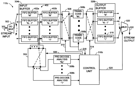
Accordingly, looking to FIG. 5, a multi-channel transcoder 112c (based on the
principles of transcoder 112b of FIG. 3) is disclosed that can be configured
to process
For example, in many embodiments, the processing steps of pre-decode analysis,
decoding, requantization, and encoding can be performed with processing
components
powerful enough to process more than one channel at a time. It should be
understood that
for example, how the algorithms are executed. For example, these processing
steps are
executed by specific-purpose hardware, such as an FPGA or an ASIC, the
performance
can be highly leveraged to concurrently process a large number of multimedia
streams,
while general purpose processors executing software designed to perform the
designated
However, it should be understood that although the embodiments described
herein
may be described in terms of reducing processing elements, some embodiments
may use a
greater number of processing elements than the number of streams being
concurrently
processed. For example, such an implementation could advantageously allow for
the
aspect is that embodiments of the disclosed transrator can change the ratio of
processing
elements from 1:1 to some other ratio being greater or less, depending on the
environment.
Like transcoder 112b of FIG. 3, operation of transcoder 112c is described with
19
CA 02644288 2008-08-29
WO 2007/136903
PCT/US2007/062929
transrating of the incoming MPEG-encoded video stream. The transcoder 112c of
FIG. 5
shares many of the same principles and components of transcoder 112b of FIG.
3.
However the important additional aspects and/or differences are highlighted
below.
Stream input 302 comprises a stream of N multiplexed multimedia bit streams.
De-multiplexer (DMUX) 502 receives and de-multiplexes the streams into N
multimedia
streams. The N streams can be provided to respective logical FIFO buffers 402
for
providing a desired delay. Transcoder 112c can include Mitranscoder units 306b
to
transcode the N input multimedia streams. The transcoder units 306b could, for
example,
generally comprise the VLD 310 and VLE 318 of FIG. 3 and/or any other
components
needed to perform a desired transcoding of the N input streams into N target
multimedia
streams. In the case of transrating the N input streams, the M, transcoder
units could also
comprise requantization element 314 of FIG. 3. According to some embodiments,
transcoding units 306b may even be configured differently to perform different
kinds of
transcoding processes.
Similarly, according to some embodiments, transcoder 112c can include M, pre-
decode analysis units that can be timeshared to analyze the N streams of
multimedia data
buffered in input data buffer 304b (L e . to provide coding statistics to
trancoding control
unit 316b).
As with transcoder 112b of FIG. 3, pre-decode analysis module 308 reads the
data
from the respective address of a memory location in one of the N logical FIFO
buffers 402
in order to perform the statistical analysis. As with FIFO buffer 402 of FIG.
4, the
specific relative memory location (i.e. block 408) from which to read from can
be selected
to obtain statistical data on a desired amount of the buffered multimedia
content in the
FIFO buffers 402.
CA 02644288 2008-08-29
WO 2007/136903
PCT/US2007/062929
However, unlike transcoder 112b of FIG. 3, the FIFO buffers 402 can be
connected to the pre-decode analysis units through a switch 504, which could
be a cross-
point switch. Switch 504 can be configured such that any of the pre-decode
analysis units
308b can be connected to any of the FIFO buffers 402 under the control of
transcode
control unit 316b. Accordingly, cross-point switch 504 may be configured with
N inputs,
connected to each of the N FIFO buffers 402. Likewise, switch 504 may be
configured
with M2 outputs, connected to each of the M2 pre-decode analysis units. Switch
504 may
further include an input for receiving control signals from control unit 316b
across control
line 506. Such control signals specify to the switch 504 which of the N inputs
and M2
outputs should be connected at a given time.
Depending on the type of analysis being performed on the buffered multimedia
streams, the time required for analyzing each portion of the stream may vary.
For
example, in the case of video streams, more complex pictures or types of
frames may
require a longer analysis time than less complex pictures. Thus, tying a
specific
processing unit to process only the streams of a particular channel (e.g. by
tying each
FIFO buffer 402 to a specific pre-decode analysis unit 308b) can potentially
cause a loss
in performance. That is, if the processing units are assigned to a particular
FIFO buffer,
the pre-decode analysis units 308b may sit idle for periods of time when they
could
otherwise be used to process data from other FIFO buffers.
Accordingly, the pre-decode analysis units 308b can be thought of as a common
pool of processing resources, and the switch 504 can be controlled to direct
portions of
the multimedia stream stored in any of the multimedia N FIFO buffers 402 to
any of the
pre-decode analysis units 308b at a time when a respective processing unit is
able to
process additional data.
21
CA 02644288 2008-08-29
WO 2007/136903 PCT/US2007/062929
The time-shared pre-processing can be performed on a predetermined portion
(i.e.
a unit) of the multimedia stream. That is, each pre-decode analysis unit 308b
can be
configured to process one or more units of the multimedia stream before moving
on to
another unit of the same or different channel. In the case of video streams,
for example,
the units may comprise the pictures of the video stream, and processing may be
performed
on a picture-by-picture basis. Thus, one picture can be analyzed by a pre-
decoder unit
308b in its entirety, before the processing is performed on a picture from the
same or
different channel. The units may vary considerably from one multimedia format
to
another. For example, MPEG-2 transcoding may use a slice, which corresponds to
a
subdivision of an individual picture. Such a slice could correspond to a row
of
macroblocks. According to other embodiments, the unit could include multiple
pictures.
Similarly, when transcoding audio, the units may correspond to audio frames,
or some
other audio sampling period.
According some embodiments, the M1 transcode modules 306b can be timeshared
among the N FIFO buffers 402 in a similar manner as the pre-decode analysis
modules
308b. Thus, a switch 508, can be configured to connect any of the M1 transcode
units
306b to any of the N FIFO buffers 402 under the selective control of transcode
control
unit 316b. Accordingly, switch 508 could be a cross-point switch and can be
configured
with N inputs that are connected to each of the N FIFO buffers 402. Likewise,
switch 508
may be configured with M1 outputs, connected to each of the M1 transcode
modules 306b.
Switch 508 may further include an input for receiving control signals from
control unit
316b across control line 510. Such control signals specify to the switch 508
which of the
N inputs to connect to the M1 outputs.
Further, a switch 512 can be configured to connect transcode units 306b to any
of
the output FIFO buffers 516 under the selective control of transcode control
unit 316b.
22
CA 02644288 2008-08-29
WO 2007/136903
PCT/US2007/062929
Accordingly, cross-point switch 512 may be a cross-point switch configured
with M1
inputs that are connected to each of the outputs of the M1 transcoder modules
306b and
also configured with N outputs connected to each of N output FIFO buffers 516.
Switch
512 may further include an input for receiving control signals from control
unit 316b
across control line 514. Such control signals specify to the switch 512 which
of the M1
inputs to connect to the N outputs.
Accordingly, under the direction of control unit 316b, each of the multimedia
streams transcoded by transcoder modules 306b can be buffered in the N output
buffers
516. A multiplexer (MUX) 520 can be configured to selectively retrieve
portions of the
transcoded multimedia stream from the N output buffers 516. MUX 520, or a
package
and scheduling module 328 (FIG. 3), may be configured to package and schedule
the units
of data comprising the multimedia stream for delivery to the remote locations
104. Such
selective retrieval, packaging, and/or scheduling may be under the control of
control unit
316b via control lines 520.
Transcoding control unit 316b performs a number of tasks, including scheduling
the pictures that are delivered to pre-decode analysis modules 308b and/or
transcode units
306b. Control unit 316b determines which pictures are delivered to a
particular
processing unit at any particular time. To do so, control unit 316b can send
control
signals over respective control lines 506 and/or 510 to configure the input
and output
connections of the respective pre-decode analysis modules 308b and/or
transcode units
306b.
The criteria used in determining the scheduling order may depend on a number
of
factors. For example, one such factor is to ensure that the pictures are
available to the
respective decoder in due time for the decoder to be able to present the
pictures according
to the fixed frame rate. In video coding this is often referred to as obeying
the decoder
23
CA 02644288 2008-08-29
WO 2007/136903 PCT/US2007/062929
buffer model. For MPEG-2, this scheduling adheres to the video-buffer verifier
(VBV)
model.
In addition to determining from which FIFO buffer 402 to obtain the next
portion
of the stream, control unit 316b also determines which of the pre-decode
analysis modules
308b and/or transcode units 306b are to receive the next portion of the
encoded bit stream
from the selected FIFO buffer 402. For example, the pre-decode analysis units
308b may
be scheduled on an availability basis, as new pictures to be analyzed become
available at
the selected position in buffer 402. This position may be, for example, block
408 of FIG.
4.
Although embodiments described above refer to each FIFO buffer 402 being a
single logical buffer, some embodiments may split each of the FIFO buffers 402
into
multiple daisy-chained FIFO buffers. For example, each FIFO buffer 402 could
be split
into two logical or physical FIFO buffers 402a and 402b, as depicted in FIG.
5. The exit
point of FIFO buffer 402a can form the selected position from which a pre-
decode
analysis module 308b retrieves its next unit of work, while the exit point of
the second
buffer right FIFO buffer 402b can feed a respective transcode unit 306b.
Control unit 316b may select any free pre-decode analysis modules 308b and/or
transcode units 306b to process a particular portion of the stream. Once the
portion of the
multimedia stream has been transferred to a pre-decode analysis module 308b
and/or
transcode unit 306b, the control unit may also be configured to send a signal
to the start
the processing.
Upon finishing its respective processing, the pre-decode analysis modules 308b
and/or transcode units 306b can be configured to send a completion signal to
control unit
316 indicating that the processing results can be retrieved and that the
respective pre-
24
CA 02644288 2008-08-29
WO 2007/136903 PCT/US2007/062929
decode analysis module 308b and/or transcode unit 306b is now available for a
new
portion of the bit stream to process.
Thus, upon receiving such a completion signal from pre-decode analysis module
308b, control unit 316b may retrieve the resulting coding statistics related
to the portion
of the stream analyzed. Likewise, upon receiving such a completion signal from
transcode unit 306b, control unit 316b may direct switch 512 to connect the
appropriate
output of transcode unit 306b to the appropriate input of a respective FIFO
buffer 516.
The transrated and re-encoded signal may then be delivered and stored in this
FIFO buffer
516.
In the case that pictures of multiple channels are ready to be processed at
the same
time, the situation may occur that no free processing resource (pre-decode
analysis
module 308b and/or transcode unit 306b) is available. In such a case, the
control unit
316b can wait for until such resource becomes available. However, a
sufficiently large
input buffer 304b can make up for such situations. Likewise, on the output of
transcode
unit 306b, output buffer 326b can be used to compensate for such delays,
including the
variable time-shift that is inherent when implementing a time-sharing
principle.
If the processing units are not able to sustain the required rate over a time
period
compensated by the buffers 304b and/or 326b, an input buffer overflow and/or
an output
buffer underflow occurs, and may be handled in a number of ways (i.e. skipping
the
processing of a particular units, etc.). Such a situation indicates an overall
overload of the
system.
Control unit 316b can be configured to collect the pre-decode data from the
pre-
decode analysis units. In the case of video, control unit 316b may then use
these
statistics to determine the settings for the transrating and/or transcoding of
the individual
pictures. Accordingly, control unit 316a may have an associated memory (not
depicted)
CA 02644288 2008-08-29
WO 2007/136903
PCT/US2007/062929
to temporarily store the statistical data until no longer needed. Accordingly,
control lines
518 between each of the M1 transcoder elements 306b and control unit 316a may
be used
to communicate any such settings from the controller 306b to a respective VLD,
VLE,
and/or requantization unit associated with a transcode module 306b.
Although the embodiments can be scaled to a variety of sizes, one such
embodiment could timeshare five transcode modules 306b among five-hundred
multimedia streams. A similar number of pre-decode analysis modules could be
timeshared among the same number of multimedia streams. Such a configuration
incorporating the time sharing of either, or both of, transcode modules 306b
and/or pre-
decode analysis modules 308b can significantly reduce the amount of hardware
needed to
implement a multi-stream transcoder.
It should be understood that is not necessary that there be equivalent numbers
of
pre-decode analysis units and transcoder units, as these processors are
independent of
each other and perform different tasks.
For the purposes of more clearly describing the timesharing aspects of the
transcode units 306b and pre-decode analysis units 308b, the specific
implementation of
input memory FIFO buffers 402b and output memory FIFO buffers 516 have been
generally depicted as being fixed-size logical or physical buffers.
Although this approach is possible, in practice, such a configuration can
become
impractical (or grossly inefficient) as the number of streams to be processed
increases.
For example, the bit rate of the streams can vary widely from channel to
channel,
particularly for different types of content. Accordingly, if the size of the
FIFO buffers are
fixed, the size is of the buffers is necessarily determined based on the
highest possible bit
rate. Accordingly, this approach can result in large amount of unused memory
under
normal operating conditions.
26
CA 02644288 2008-08-29
WO 2007/136903 PCT/US2007/062929
Thus, the transcoder embodiments disclosed herein can implement a dynamic-
memory allocation scheme in which the size of the FIFO buffers can be
dynamically
allocated on an as-needed basis. According to such an embodiment, buffers 304b
and
326b can be implemented as one or more physical memory blocks. However, the
FIFO
buffers 402b and 516 can be implemented as logical units (instead of physical
units) that
reside in the physical memory.
FIG. 6 depicts an embodiment of a transcoder 112d, based on the principles of
transcoder 112c of FIG. 5. Transcoder 112d may include memory controllers 604
and
606 which can function to dynamically allocate memory to the FIFO buffers as
well as
function as logical switches.
Specifically, according to some embodiments, transcoder 112d can dynamically
allocate the memory used by the FIFO buffers 402b and 516 of FIG. 5. According
to such
an embodiment, one or more physical memory modules 602 represent the physical
storage
devices for the input data buffer 304b and 326b of FIG. 5. Further, an input
buffer
memory controller 604 and an output buffer memory controller 606 can be
configured to
control and maintain the dynamic allocation of the memory. Controllers 604 and
606 can
also be configured to function as a logical switch between the FIFO buffers
and the
transcoder units 306b and/or pre-decode analysis units 308b.
With respect to the dynamic memory allocation, memory controller 604 may
maintain the memory allocated to each FIFO buffer in an allocation table 608.
According
to some embodiments, the allocation table 608 may maintain a list comprising
an entry for
each memory segment, which is the smallest amount of memory used for
allocation.
Upon request from a FIFO buffer 402b or 516, memory controller 604 can
allocate a free
memory segment. The allocation table holds a "next pointer" for each segment,
which
points to the next segment to create a linked list. The last segment in the
list has a NULL
27
CA 02644288 2008-08-29
WO 2007/136903 PCT/US2007/062929
pointer, indicating that no segment follows. This list defines the memory for
a logical
FIFO, and such a list can be traced in the allocation table for every logical
FIFO.
A FIFO pointer table 610 may also maintain memory address information about
each of the FIFO buffers 402b and/or 516. According to some embodiments, FIFO
pointer table 610 contains a write pointer and a read pointer for each FIFO
buffer. The
write pointer points to the segment, and the location in the segment, where
the next data is
to be written. When data has been written, the write pointer is updated to
point to the
next position. When the last memory cell of the segment is used, a new segment
is
allocated and the allocation table for the last segment in the list is updated
to point to the
new segment, which then becomes last (pointing to NULL). The write pointer is
updated
to point to the first element of the new segment.
Likewise, the read pointer points to the segment and the position within the
segment of the first unread element in the FIFO buffer, and the read pointer
is updated
whenever data is read from the segment. When the last data in a segment is
read, the read
pointer is updated using the "next pointer" from the allocation table to point
to the next
segment in the list. The previous segment is no longer used and is returned to
the end of a
list of the free segments.
A free list, which comprises a linked list of free segments in the allocation
table, is
also maintained. When segments are allocated they are taken from the top of
the free list.
A pointer defines the start of the list, by pointing to the first free
segment, and another
pointer points to the last element. The latter is used for returning segments
to the free list.
In the case that each FIFO buffer 402 is a single logical buffer used to feed
both
pre-decode analysis unit 308b and transcode module 306b, each FIFO buffer 402
includes
two read ports and two read pointers (one to feed pre-decode analysis units
308 and one to
feed transcode modules 306b). Of course the read pointer for pre-analysis
(e.g. to read
28
CA 02644288 2008-08-29
WO 2007/136903 PCT/US2007/062929
data into a pre-decode analysis unit 308b) does not free up memory since the
buffer still
holds this data for the transcode processing.
As briefly introduced above, memory controller 604 can be configured to
function
as switches 504 and 508 of FIG. 5 (here represented by logical switch modules
504a and
508a). The switches are logical in the sense that connections are defined by
the use of
memory addresses rather than physical connections.
Similarly, memory controller 606 may maintain the memory allocated to each
output FIFO buffer 516 in an allocation table 612. A FIFO pointer table 614
may
maintain memory address information about each of the output FIFO buffers 516.
Furthermore, memory controller 604 can be configured to function as the switch
512 of
FIG. 5 (here represented by logical switch 512a).
In addition to the benefits of sharing physical memory modules 602, the
disclosed
dynamic memory scheme has further advantages with respect to the reduced
number of
memory interfaces in comparison to embodiments using separate physical buffers
for each
stream. For example, an embodiment using separate physical FIFO buffers use
input and
output interfaces for each FIFO buffer. In contrast, physical memory 602 can
have one
common read-write interface for all logical FIFO units 402b and/or 326b. The
common
interface is, however, at the expense of a higher bandwidth for this
read/write port.
With respect to the number of physical memory modules 602, a single common
block can be more efficient. For example, in practice, subdividing the
physical memory
into smaller blocks can cause an increasing loss of usable memory. This is
because of the
difficulties in sharing memory between multiple physical blocks. However, for
practical
reasons, a subdivision into more than one module may be chosen, and a trade-
off can be
made between what is practical and what is most efficient.
29
CA 02644288 2008-08-29
WO 2007/136903 PCT/US2007/062929
Like the processing units, the access to the physical memory modules 602 are
timeshared among the pre-decode analysis and transcoder modules. The multi-
port access
to the memory from such transcoding and analysis modules can be translated
into the
single port memory interface through the memory controllers 604 and 606. Thus,
the
number of interfaces to the memory controller is determined by the number of
attached
pre-decode analysis and transcoder modules.
Thus, it should be understood that the processing time for each portion of the
multimedia stream, as well as the memory requirements needed, will vary
depending on a
number of factors such as the bit-rate of the input video stream. Using the
disclosed
embodiments, the memory and/or processing resources of the transcoder are
advantageously timeshared. Specifically, the physical memory 602, the pre-
decode
analysis modules 308b, and/or the transcoder modules 306, can all be
timeshared to
reduce the hardware and memory requirements for processing a large number of
multimedia streams.
Accordingly, many varieties of multimedia channels can be processed
efficiently.
Whether there are a large number of low-bit rate channels, a few high bit-rate
channels, or
a mix of channels having a variety of bit rates, no reconfiguration of the
hardware is
necessary. The capability of the chosen design of the disclosed transcoders to
process a
desired number of channels depends more on the aggregate bit rate at the
input, rather
than the specific configuration (i.e. performance or size) of the individual
buffers, pre-
decode analysis modules, or transcoder modules.
Among other advantages, transcoder systems and methods have been disclosed
that can be advantageously scaled to process a large number of multimedia
streams
without excessive memory requirements and/or duplicative or underutilized
hardware. It
should be emphasized that many variations and modifications may be made to the
above-
CA 02644288 2008-08-29
WO 2007/136903
PCT/US2007/062929
described embodiments. All such modifications and variations are intended to
be
included herein within the scope of this disclosure and protected by the
following claims.
31