Note: Descriptions are shown in the official language in which they were submitted.
CA 02644603 2008-11-20
[001] SUPPORT GRID PLATFORM FOR SUPPORTING VEHICLES
OVER ECOLOGICALLY SENSITIVE TERRAIN
[002] FIELD OF THE INVENTION
[003] This invention relates to a platform especially suited for use
supporting
vehicle wheels to provide traction while traveling off-road especially through
environmentally sensitive topography and to prevent unnecessary and excessive
wear and damage to such off-road paths or trails. More specifically, this
invention
relates to a grid-type platform designed to provide all-terrain vehicles
(ATVs) and
four-wheel drive vehicles the necessary traction to reduce tire slippage and
rutting
when traveling through off-road trails or paths particularly through
environmentally
sensitive areas. Furthermore, this invention will minimize ecological damage,
destruction and wear, for example, to wetlands, by retaining loose or
saturated soil,
rock, sand, etc., on the off-road trails.
[004] BACKGROUND OF THE INVENTION
[005] Over recent years, all-terrain vehicles (ATVs) and four-wheel drive
(4WD)
vehicles have become more and more popular for recreational purposes.
"Off-roading" or "four-wheeling" are terms used to describe the act of driving
an
AN or 4WD vehicle off a normal paved or unpaved streets. Off-roading is
usually
done in rural areas on trails, open fields or wooded areas. While some people
use AN or 4WD vehicles for transportation to hunting or fishing grounds, most
people use them strictly for recreational purposes.
[006] There are many state parks and private land owners which allow AN
and 4WD vehicles, usually on marked trails. One of the biggest problems faced
with these off-road ing trails is that because of the rather large tires and
necessary
engine torque inherent in such ATVs substantially deep ruts and grooves begin
to
form in the trails, especially in low-lying wetlands, after excessive use.
Consistent
wear on a trail by AN and 4WD vehicle tires can cause irreparable ecological
CA 02644603 2008-11-20
-2-
damage to the trail and to the local environment especially in ecologically
sensitive
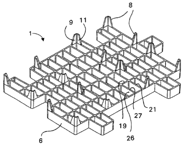
areas such as wetlands.
[007] The deep treaded tires found on ATV and 4WD have a damaging effect on
nearly all types of surfaces. On a hard surface, such as a paved road, a tire
is very
efficient. An ATV or 4WD vehicle can move forward with the engine at an idle
and
very little power. Loose dirt on the hard surface will be compressed, but not
kicked-up or displaced. On such a surface, there is minimal wear damage,
however, the loose dirt on the hard surface may be displaced and eventually
erode
the surface until it reaches a near irreparable state.
[008] On softer surfaces, such as a meadow, open field or wetland, the
wheel and
tire will typically sink into the surface under the weight of the vehicle. In
these
situations, the tire has to continually climb out of the depression it has
created.
This continuous climb requires extra power, similar to a car climbing up a
hill at a
similar angle to the tire climbing out of its depression. The climb out is
such hard
work for the tire that the lugs slip a small amount before they can compress
the soil
behind the lug enough to grip the surface. This slippage is constant as the
vehicle
moves forward. As the tire slips, plants under the tire are torn or pulled
from the
ground. On these surfaces, it takes as few as one vehicle to cause permanent
damage to the ground, wetland and the vegetation.
[009] No matter how slowly and carefully a vehicle is driven on soft
ground,
the tire always has to climb at a climb out angle and, therefore, a certain
amount
of slippage and resulting damage always occurs. In fact, high speed may cause
less damage on softer ground because there is less time for a deeper
depression
to occur and thus the climb out angle would be less.
[010] On very soft ground, such as a wetland, an open field after a heavy
rain or
a meadow at the base of a steep hill, the tire sinks even deeper than in the
previous situation. This deeper depression increases the climb out angle and,
therefore, more power is needed. As previously described, the tire must
overcome
the greater angle and, therefore, even greater slippage and thus more
destruction
results. In these situations, it is common for the tires to be slipping to the
point
CA 02644603 2008-11-20
-3-
where the dirt and plants which have been compressed will be thrown in the air
behind the vehicle.
[011] There may be situations where the ground is so soft and corresponding
climb out angle is so steep that the tire spins and the vehicle comes to a
halt.
As the tire spins into a near vertical wall, dirt and plants are constantly
thrown high
into the air as the vehicle sinks deeper and deeper in the rut it has created.
[012] Many states in the U.S. have passed laws and regulations banning ATVs
and 4WD vehicles from certain parks and areas where the ecological system is
too
fragile to withstand the damage imposed by use of such vehicles. In some
jurisdictions, it is required to use structures for minimizing such trail wear
in an
attempt to minimize the damage. Traction mats and vehicle support platforms
are
one solution to this problem.
[013] Traction mats and vehicle support platforms, known in the art, are
similar
to the present invention, but with certain drawbacks. One of the largest
problems
with many of the traction mats known in the art is that they are very
expensive to
manufacture. They are typically made of a heavy material so as to withstand
the
weight of a vehicle without suffering from permanent deformation, however,
many
still become permanently warped from continued use. Another problem with
previously known vehicle support platforms is their inability to easily
connect with
another adjacent platform. Many platforms use a pin-pinhole connection method
which makes the platforms very difficult to move once it is placed on the
ground.
Others are not capable of interlocking or interconnecting with other platforms
at all.
[014] Figs. 1 and 2 show two types of traction mats known in the art at the
time
of the invention. Viewing Fig. 1, the traction mat is made up of certain basic
structural features found in door mats used in association with entrance doors
of
buildings and other places to provide a convenient walking surface for
catching
mud, dirt or snow from a person's shoes walking thereon. These types of mats
are
constructed with a unvarying construction and uniform planar upper and lower
surfaces.
[015] This mat comprises a series of serpentine traction strips which may
be
formed from any suitable metal or high-impact plastic. Each strip has
CA 02644603 2008-11-20
-4-
alternately opposing undulations defining corresponding alternating openings.
The undulations are substantially U-shaped with leg portions that slightly
diverge
so that the crest portions can fit inter-digitally by projecting into the
mouth ends of
each opening.
[016] The inter-digited crest portions of the undulations are articulately
coupled
by way of suitable hinge pin rods desirably formed from gauge wire and
extending
through aligned holes. To retain the rods against endwise displacement, they
are
provided with a locking means at their opposite ends. For support at each
opposite end of the mat, reinforcing and stabilizing means, such as a closure
strip
bar, may be provided and which may be formed from the same strip material as
the traction strips or may be of a slightly heavier gauge, if preferred. Each
of the
end bars is secured to the crests of the endmost undulations of the mat as by
means of rivets.
[017] Another type of traction mat, as shown in Fig. 2, is primarily made
from a
plurality of parallel linear strips arranged with the sides of an elongated,
generally
rectangular protecting grid having a high traction top surface. A second
series of
parallel linear strips is positioned to the sides of the protecting grid. The
grid is
fitted on one side with an interlocking means adapted to fit one grid to
another.
This interlocking means may consist of adapting sides with a plurality of
spaced
apertures therein.
[018] SUMMARY OF THE INVENTION
[019] There is a need in the art for a vehicle support platform which can
overcome
the previously discussed problems. The present invention is directed at
further
solutions to address this need.
[020] In accordance with one aspect of the present invention, a vehicle
support
platform is designed to disperse the weight of a vehicle and provide improved
traction on unstable terrain surfaces.
[021] In accordance with another aspect of the present invention, a vehicle
support platform has a non-interlocking jigsaw, profile structure with
congruent
CA 02644603 2008-11-20
-5-
surface features so the sidewalls of adjacent vehicle support platforms
compliment
one another.
[022] A further aspect of the present invention is to provide a vehicle
support
platform with a reinforced grid structure to enhance strength and minimize
weight.
[023] Yet another aspect of the present invention is providing
strategically
positioned cleats to the underside of the vehicle support platform to
stabilize
motion and to provide a retention support for the platform on the ground
underneath.
[024] The invention relates to a vehicle support platform for use in
protecting
off-road trails and ecologically sensitive terrain comprising a molded
platform
having a contiguous sidewall defining an outer edge of the platform and
connecting
a plurality of longitudinal and lateral intersecting support walls defining a
planar top
and bottom surface for supporting a vehicle thereon; a plurality of cleats
depending
from the bottom surface of the platform, at least one of a recess or
projection
formed by the sidewall in the outer edge of the molded platform; the recess or
projection being sized to receive or to be received by a corresponding
projection
or recess in an adjacent vehicle support platform.
[025] The invention also relates to a method of protecting off-road trails
and
ecologically sensitive terrain from damage from off-road vehicles, the method
comprising the steps of placing a molded platform in a desired location having
a
contiguous sidewall defining an outer edge of the platform and connecting a
plurality of longitudinal and lateral intersecting support walls defining a
planar top
and bottom surface for supporting a vehicle thereon; affixing the molded
platform
into the terrain by a plurality of cleats depending from the bottom surface of
the
platform; aligning the molded platform with at least a second adjacent molded
platform by forming at least one of a recess or projection in the sidewall in
the
outer edge of the molded platform; the recess or projection being sized to
receive,
or to be received by a corresponding projection or recess in the second
adjacent
molded platform.
CA 02644603 2008-11-20
-6-
[026] BRIEF DESCRIPTION OF THE DRAWINGS
[027] Fig. 1 is a top broken view of a known traction mat;
[028] Fig. 2 is a top elevational view of another known traction mat;
[029] Fig. 3 is a perspective view of the top surface of one embodiment of
the
present invention designed for use in flat terrain;
[030] Fig. 4 is a perspective view of a bottom surface of the first
embodiment of
the present invention designed for use in flat terrain;
[031] Fig. 5A, 5I3 and 5C are cross-sectional front, side and perspective
elevational views of the present invention designed for use in flat terrain;
[032] Fig. 6 is a top planar view of the top surface of the grid support of
the first
embodiment;
[033] Fig. 7 is a perspective view of the top surface of a second
embodiment of
the present invention designed for use in sloping, hilly terrain;
[034] Fig. 8 is a perspective view of a bottom surface of the second
embodiment
of the present invention designed for use in sloping hilly terrain,
[035] Fig. 9A, 9B and 9C are cross-sectional front, side and perspective
elevational views of the present invention designed for use in sloping, hilly
terrain;
[036] Fig. 10 is a top planar view of the top surface of the grid support
of the
second embodiment;
[037] Fig. 11 is perspective view of a third embodiment of the present
invention;
[038] Fig. 12 is a side elevation view of the third embodiment;
[039] Fig. 13 is a top plane view of the grid support of the third
embodiment;
[040] Fig. 14 is a top plan view of an alternative arrangement of the peg
bars for
the grid support of the third embodiment;
[041] Fig. 15 is a perspective view of the support grid split into separate
sections
along a longitudinal cut channel;
[042] Fig. 16 is a perspective view of the support grid split into separate
sections
along a lateral cut channel; and
[043] Fig. 17 is a top plan view of a series of grid supports and grid
support pieces
arranged to form a pedestrian walkway.
_______________________________ CA 02644603 2008-11-20
-7-
[044] DETAILED DESCRIPTION OF THE INVENTION
[045] The present invention, a vehicle support grid 1 shown in a first
embodiment
in Fig. 3, is defined, in general, by a framework which is a substantially
rigid,
single-piece, molded grid structure. The vehicle support grid 1 is defined by
a top
surface 2 and a bottom surface 4 and delineated by an outer perimeter sidewall
6.
A plurality of depending cleats 8 extend from the bottom surface 4 of the grid
structure in order to provide an adequate means of securing the grid structure
into
a desired ground surface. Preferably, the cleats 8 are integrally positioned
depending from the outer perimeter sidewall 6 of the vehicle support grid 1,
however, it is possible to place the cleats 8 at any location depending from
the
bottom surface 4 of the platform to accommodate various terrain surfaces.
[046] Each vehicle support grid 1 has a lateral width wand a longitudinal
length L,
the width w being in the range of about 30 to 60 inches, preferably about
42 inches, and the length being in the range of about 25 to 40 inches,
preferably
about 30 inches. The sidewall height is between about 2-5 inches and
preferably
about 3 inches, and the length of the depending cleats 8 between about 2 to
inches and preferably about 3 inches. It is important to note the right
angular
formation of the cleats 8 which facilitates maintaining the support grid in
position
once positioned on the ground. The right angular nature of the cleats 8
presents
perpendicularly adjacent walls 9 and 11 to provide both lateral and
longitudinal
support horizontally against the ground into which the cleats 8 are placed.
Such lateral and longitudinal support keeps the support grid 1 from moving
horizontally or twisting once positioned in the ground.
[047] It is to be appreciated that the lateral width w, length L, sidewall
height,
and cleat length may be variable to some extent, and should not be unduly
limited
by the above noted ranges, however, it is important that within such ranges as
defined above, the vehicle support grids 1 are easily stacked, carried and
placed
at an appropriate trail location by hand or from an ATV vehicle itself.
[048] The vehicle support grid 1 has a grid pattern encompassed by the
outer
perimeter sidewall 6 composed of intersecting longitudinal reinforcement bars
10
and lateral reinforcement bars 12. For purposes of the following description,
_______________________ CA 02644603 2008-11-20
-8-
a longitudinal axis 12 is defined through the center of the vehicle support
grid 1
aligned parallel with the longitudinal reinforcement bars 10 and also aligned
in the
general direction in which an ATV vehicle will travel over the support grid 1.
A lateral axis A is correspondingly defined through the middle of the support
grid 1,
but parallel aligned with the lateral reinforcement bars 12 substantially
perpendicular to vehicle travel.
[049] The longitudinal and lateral reinforcement bars 10, 12 intersect
perpendicular with one another and are each provided with respective top
edges 18, 20 which are co-planer with one another and further define the top
surface 2, as well as bottom edges 19, 21 also co-planar with one another and
together define the bottom surface 4 of the support grid 1 as seen in Fig. 4.
[050] The embodiment shown in Figs. 3-6 is generally for being positioned
on
relatively flat ground as opposed to a second embodiment to be discussed below
for placement on a slope. In this first embodiment, the perpendicularly
aligned
longitudinal and lateral reinforcement bars 10, 12 define a plurality of grid
sections 24. As seen in Fig. 6, each grid section 24 in the present embodiment
is
shown substantially as square or rectangular in nature, although other shapes
may
be possible as well, where each side of the grid section is formed by portions
of the
intersecting longitudinal and lateral reinforcement bars 10, 12. Each grid
section
24 is divided by an intermediate longitudinal reinforcement bar 26, or web,
which
is aligned parallel, but spaced from the longitudinal reinforcement bars 10
forming
the sides of each grid section 24. Correspondingly, the intermediate
longitudinal
reinforcement bar 26 is integrally connected at a right angle with opposing
sides
of the grid sections 24 formed by the lateral reinforcement bars 12.
[051] The support grid 1 is usually placed on the ground in a position
where the
longitudinal axis ti) of the support grid 1 is aligned parallel with the
direction of
travel of the vehicle to be supported. In this arrangement, the wheels of the
vehicle generally grip the lateral reinforcement bars 12 as the vehicle wheels
travel across the support grid 1 in a manner perpendicular to the lateral axis
A.
The longitudinal reinforcement bars 10 provide little traction or friction to
assist in
moving the vehicle forward, except for providing structural support to the
lateral
CA 02644603 2015-09-18
- 9 -
,
reinforcement bars 12 and, of course, some vertical support to the vehicle
wheels. However, the longitudinal reinforcement bars 10 do impede lateral
slippage or sliding of the wheels by intersecting between extending portions
of
the tire tread, often referred to as "knobbies". These knobby extending
protrusions from the wheel are blocked or impeded from lateral movement
along the lateral axis A because the knobbies are permitted by the above
discussed structure of the grid sections 24 to extend below the level of the
top
surface 2 as defined by the top edges 18, 20 of the longitudinal and lateral
reinforcement bars 10, 12. This is further facilitated by the shorter
intermediate
longitudinal reinforcement bar 26 allowing more of the vehicle wheels and the
knobby tread to fall within the grid section 24 to grip the lateral and
intermediate
reinforcement bars 12 and 26.
[052]
Observing the side, cross-sectional view of Fig. 5A, the
intermediate longitudinal reinforcement bar 26 in each grid section 24 has a
height h less than that of the adjacent lateral reinforcement bars 12. The
intermediate longitudinal reinforcement bar 26 extends from a bottom edge 27
generally aligned co-planar with the bottom surface 4 of the support grid 1,
to a
top edge 29 spaced from, i.e., lower than the top surface 2. The intermediate
longitudinal reinforcement bar 26 also connects the lateral reinforcement bars
12 forming the sides of each relative grid section. The lateral and
longitudinal
reinforcement bars 10, 12, are similar in height to the sidewall 6, thus being
in
the range of about 2 to 5 inches and preferably about 3 inches. The thickness
of
the sidewall, reinforcement bars, intermediate reinforcement bars as well as
the
cleats 8 being about .25 to .5 of an inch and preferably about .38 of an inch.
The intermediate longitudinal reinforcement bar 26 has a height h may be about
one half the height of the longitudinal and lateral reinforcement bars 12, but
is
generally in the range of about 1 to 2.5 inches and preferably about 2 inches.
As discussed, this assists with the traction of the vehicle by allowing a
certain
amount of the tread and the wheel to fall below the top surface 2 of the
support
grid 1 as defined by the top edges 18, 20 of the lateral and longitudinal
reinforcement bars 10, 12. This permits more of the vehicle wheel to grip both
CA 02644603 2015-09-18
- 10 -
,
the lateral and intermediate longitudinal reinforcement bars 10, 26 to provide
traction, as well as permit additional contact and traction with the ground
surface which becomes interspersed between grid sections 24.
[053] It is notable that the intermediate longitudinal support 26 could
also be aligned in parallel with the lateral reinforcement bars 12, however in
the
preferred embodiment the intermediate longitudinal supports 26 are parallel
aligned with the longitudinal reinforcement bars 10 so that the torque applied
by
vehicle wheels perpendicularly directly against the lateral reinforcement bars
12
is better supported. In other words, where the vehicle direction of travel is
substantially along the longitudinal axis , the torque applied by the wheels
of
the AN to the support grid 1 will generally be born directly by the lateral
reinforcement bars 12 where they are contacted directly by the wheel. Without
support, such torque could cause the lateral reinforcement bars 12 to twist,
deform or even break. With the perpendicular support of the intermediate
longitudinal supports 26 in addition to the support provided by the
longitudinal
reinforcement bars 10, the lateral reinforcement bars 12 are bolstered to
resist
the direct torque applied by vehicle wheels.
[054] Turning to Fig. 6, the vehicle support grid 1 is further defined by
the grid sections 24 being adjacently formed in lateral rows 30 and
longitudinal
columns 32. In an advantageous aspect of the present invention, certain of
these rows 30 and columns 32 are offset lateral rows 34 or offset longitudinal
columns 36 from one another. This arrangement of offset lateral rows 34 and
offset longitudinal columns 36 forms a jigsaw-like circumferential profile of
the
outer perimeter sidewall 6. By offsetting a lateral row of grid sections 24 by
one
grid section, a profile in the sidewall 6 is created having at least a recess
40 on
one side of the support grid 1 and a protruding grid square 42 defining the
sidewall on the opposing side of the support grid, Le., on the other end of
the
respective lateral row. Similarly, one or more offset longitudinal columns 36
of
grid sections 24 could be offset from the other columns 32 so that a recess 41
is formed in one end of the support grid 1 and a protruding grid square 43
extends at the opposite end of the support grid 1 from the recess.
CA 02644603 2008-11-20
-11-
[055] It is also to be appreciated that the offset rows and columns 34, 36
do not
have to be offset as described above or offset by a complete grid square 24.
It could be that certain rows and columns may define a recess 40, 41 by
providing
one less grid section or a smaller grid section on the peripheral edge of the
support
grid 1 defining the sidewall 6. Similarly, an additional grid section or
partial grid
section may compliment the end of any row or column of grid sections 24 to
provide a protruding extension 42, 43 to the sidewall 6 of the vehicle support
grid 1.
[056] It is to be recognized that each vehicle support grid 1 has a similar
jigsaw-
like profile of the sidewall 6 and thus each opposing side and opposing end of
each vehicle support grid 1 being respectively complimentary, so as to
flexibly
engage and interleave with an adjacently positioned support grid 1. In this
manner, the individual vehicle support grids 1 may be laid side by side and
end-to-end and interleaved to the extent that while each vehicle support grid
1 may
move independently in a vertical direction relative to one another and the
ground.
The support grids 1 are interleaved with the recess' 40,41 defined on one
support
grid 1 engaging the corresponding protruding grid squares 42, 43 in the
adjacent
grid support sidewall 6, so as to prevent relative planar movement and
rotation
between one another and to prevent lateral and longitudinal displacement
relative
to one another and the ground.
[057] When the support grid 1 is placed on the ground, whether on a trail,
an open field or any other natural surface, the cleats 8 will sink into the
ground until
the bottom surface 4 of the support grid 1 presses against the ground surface.
Although the support grid 1 may continue to sink down with use and time, the
top
surface 2 of the platform defines the new support surface for any off-road
vehicle
over the terrain. Although the soft, saturated or loose ground surface upon
which
the support grid 1 is placed may flow or be forced up into the grid sections
24,
especially over time and use, this support grid 1 and the top surface 2
thereof,
allows for a vehicle to travel along the trail, field, etc., without
significantly
impacting or destroying the ground underneath the support grid I. As several
of
these platforms are laid adjacent and interleaved with one another, it is
possible
_______________________________ CA 02644603 2008-11-20
-12-
to cover the entire length of a desired environmentally sensitive area with
these
platforms without significantly disturbing the ground underneath and
preventing
further disruption, erosion or rutting.
[058] Lastly, in this embodiment the preferable spacing between lateral
reinforcement bars 12 is about 5 to 6 inches and also about 5 to 6 inches
between
longitudinal reinforcement bars 10. In this regard, the intermediate
reinforcement
bars are thus parallel spaced from the longitudinal reinforcement at about 2.5
to 3 inches. Such spacing can be important to the usefulness and function of
the
present invention in regards to ATV vehicles. If the grid sections 24 are too
small,
very little of the tire will be able to grip the reinforcement bars and the
potential to
slide off the support grid 1 and into the unprotected terrain is increased. If
the grid
sections 24 are to large, more radial surface are of the wheels will fall
below the
surface 2 of the support grid 1 and the ATV wheels will labor and thus require
more
torque to overcome the impediments presented by the reinforcement bars.
[059] The jig-saw pattern of the present invention as discussed above
allows for
two similarly positioned adjacent support grids 1 to fit geometrically
together
without a secured fastening type device directly between each individual
support
grid 1 as shown in the previously known traction mats. Therefore, when one
support grid 1 is already defining a pathway and a second support grid 1 is
placed
in the same direction, adjacent to the first support grid 1, the interleaved
recesses
and protruding grid sections will allow for each support grid 1 to have the
ability to
withstand the weight of a vehicle independently without transferring the
vertically
induced forces to adjacent support grids 1. However, because the jig-saw fit
limits
the degree of planar rotation between adjacent support grids 1, the platforms
will
not twist relative to one another and the pathway created by these platforms
remains intact.
[060] In Figs. 7-10, a further embodiment of the vehicle support grid us
designed
in regards to the needs of the off-road vehicle while traveling on sloped
terrain.
In this second embodiment in which like elements are identified by the same
reference letters and numerals as in the first embodiment, a complete
description
of the common elements is not provided for sake of brevity. The difference in
_______________________ CA 02644603 2008-11-20
-13-
structure between this second embodiment and that previously disclosed is
the alternation in the arrangement and height of certain of the longitudinal
reinforcement bars 10 in order to provide better grip or traction for the
vehicle
wheels when traveling uphill or downhill.
[061] This novel sloping terrain structural arrangement can be explained
by
understanding the increase in required torque for a vehicle traveling up or
down an
incline. When traveling on flat terrain, low to medium torque is sufficient to
accelerate the vehicle under normal operating conditions. As the vehicle
begins
to ascend a slope, the necessary torque is greatly increased to compensate for
the
gravitational forces acting against the vehicle. Therefore, there is a much
greater
demand for power from the tires and hence an increase in torque to the wheels
can lead to slippage between the wheels and the ground.
[062) Observing a central portion of the vehicle support grid 1 as shown
in Fig. 7,
the longitudinal reinforcement bars 10, which define respective sides of the
grid
sections 24, are lowered to be the same or similar height as the intermediate
longitudinal reinforcement bars 26. In this manner are created a plurality of
adjacent intermediate longitudinal reinforcement bars 26 within elongate,
rectangular shaped grid sections 25. These rectangular shaped grid sections 25
are aligned with their longer sides defined by the lateral reinforcement bars
12
parallel with the lateral axis A to facilitate better traction of the vehicle
wheels as
discussed in further detail below.
[063] In this second embodiment, these plurality of adjacent intermediate
reinforcement bars 26 may have a height of between about 1 to 2.5, and more
preferably about 2 inches. The remaining longitudinal and lateral
reinforcement
bars 10, 12 may be generally the same height as described with respect to the
first
embodiment.
[064] Similar to the first embodiment, the vehicle support grid 1 of the
second
embodiment is defined by the grid sections 24 and, also in this case, elongate
grid
sections 25, being adjacently formed in lateral rows and longitudinal columns
32.
In an advantageous aspect of the present invention, certain of these rows and
columns are offset lateral rows 34 or offset longitudinal columns 36 from one
CA 02644603 2008-11-20
-14-
another. This arrangement of offset lateral rows 34 and longitudinal columns
32
forms a jigsaw-like circumferential profile of the outer perimeter sidewall 6.
By offsetting a lateral row of grid sections 24 by one grid section, a profile
in the
sidewall is created having a recess 40 on one side of the support grid, and a
protruding grid square 42 defining the sidewall on the opposing side of the
support
grid, i.e., on the other end of the respective lateral row. Similarly, one or
more
longitudinal columns 32 of grid squares could be offset from the other columns
so
that a recess 41 is formed in one end of the support grid and a protruding
grid
square 43 extends at the opposite end of the support grid from the recess 41.
[065] It is also to be appreciated that the rows and columns do not have
to be
offset as described above or offset by a complete grid section. It could be
that
certain rows and columns may define a recess 40, 41 by providing one less grid
section or a smaller grid section on the peripheral edge of the support grid 1
defining the sidewall. Similarly, an additional grid section or partial grid
section
may compliment the end of any row or column of grid sections 24 to provide a
protruding extension 42, 43 to the sidewall 6 of the vehicle support grid 1.
1066] Ills to be recognized, observing Fig. 10, that each vehicle support
grid 1 has
a similar jigsaw-like profile of the sidewall 6 and thus each opposing side of
each
vehicle support grid 1 being respectively complimentary so as to flexibly
engage
and interleave with one another. In this manner, the individual vehicle
support
grids 1 may be laid side by side and end to end, and interleaved to the extent
that
while each vehicle support grid 1 may move independently in a vertical
direction
relative to one another and the ground, the support grids 1 are interleaved
with the
recess 40 defined on one support grid 1 engaging the corresponding protruding
grid square 42 in the adjacent grid support sidewall 6, so as to prevent
relative
planar movement and rotation between one another, and to prevent lateral and
longitudinal displacement relative to one another and the ground. In general
the vehicle support grids 1 of both the first and second embodiment have
complimentary recesses and protruding grid sections 42, 43 so that flat
terrain
sections of the support grids 1 will interleave also with the sloping terrain
support
grids 1 of the second embodiment.
CA 02644603 2008-11-20
-15-
[067] Also, as seen in Fig. 7 the grid sections 24 making up the left and
right
sides, i.e., the longitudinally aligned grid sections 24 making up the left
and right
sides on either side of the elongate grid sections 25 may be of different
sizes.
For example, observing Fig. 7, the grid sections on the right side of the
support
grid 1 may have a plurality of intermediate supports 26, where the grid
sections on
the left side are most similar to those of the first embodiment with only one
intermediate support 26. This may facilitate better traction of a vehicle
towards a
center of adjacently side by side positioned support grids 1.
[068] Turning to Fig. 9A, by lowering the height of certain of the adjacent
longitudinal reinforcement bars 26 in the sloping terrain support grid 1 of
the
second embodiment to create the elongate grid sections 25, this embodiment
allows for more surface area on the outer circumference of the tire to "sink
in" to
the platform, i.e., a larger radial portion of the wheel falls below the top
surface 2
of the vehicle support grid 1, into the elongate grid section 25. The depth to
which
the radial portion of the wheel will fall is defined by the height h of the
lower
intermediate reinforcement bars 26. Thus, the wheel is provided with more
circumferential surface area to grip, minimizing slip and maximizing traction
between the wheel and the support grid 1. Greater traction allows the tire to
more
easily climb the sloped incline while also minimizing the risk of the vehicle
slipping
and sliding on an incline and creating damage to the trail.
[069] In a further embodiment of the present invention, a support grid 51
is shown
in Fig. 11 having a framework which, like the previously described embodiment
is
a substantially rigid, single-piece, molded grid structure. Also similar, the
support
grid 51 is defined by a top surface 52 and a bottom surface 54 and delineated
by
an outer perimeter sidewall 56. Different from the previous embodiment,
support
grid 51 has no integral cleats depending from the bottom surface 54. Instead,
a
series of peg bars 58 are provided to receive a separate peg (not shown) for
assisting in anchoring the support grid 51 if necessary. A further description
of the
peg bars 58 is provided below. Without the cleats, the present embodiment can
be turned, or flipped over so that the bottom surface 54, described in further
detail
below, constitutes a substantially planar support surface with smaller grid
sections
- ¨
CA 02644603 2008-11-20
-
-16-
for pedestrians, i.e. human foot traffic, as opposed to the top surface 52
which is
generally designed as a surface for vehicles with tires.
[070] Each vehicle support grid 51 has a lateral width w and a longitudinal
length L, the width w being in the range of about 30 to 60 inches, preferably
about
42 inches, and the length being in the range of about 25 to 40 inches,
preferably
about 30 inches. The sidewall height is between about 2-5 inches and
preferably
about 3 inches. It is to be appreciated that the lateral width w, length L and
sidewall height may be variable to some extent, and should not be unduly
limited
by the above noted ranges, however, it is important that within such ranges as
defined above, the support grids 51 are easily stacked, carried and placed at
an
appropriate trail location by hand or from an AN vehicle.
[071] The support grid 51 has a grid pattern encompassed by the outer
perimeter
sidewall 56 composed of intersecting longitudinal reinforcement bars 60 and
lateral
reinforcement bars 62. For purposes of the following description, a
longitudinal
axis Q is defined through the center of the support grid 51 aligned parallel
with the
longitudinal reinforcement bars 60. A lateral axis A is correspondingly
defined
through the middle of the support grid 51, but parallel aligned with the
lateral
reinforcement bars 62.
[072] The longitudinal and lateral reinforcement bars 60, 62 intersect
perpendicular with one another and are each provided with respective top
edges 61, 63 which are co-planer with one another and further define the top
surface 52, as well as bottom edges 55, 57 also co-planar with one another and
together define the bottom surface 54 of the support grid 1 as seen in Fig. 11
and
12.
[073] The embodiment shown here is for use as either a support grid 51 for
vehicles where the top surface 52 is exposed and the bottom surface 54 in
contact
with the ground, or upon the support grid 51 being flipped over so that the
bottom
surface 54 is exposed and the top surface 52 is in contact with the ground,
the
device may be used for a walking path for pedestrians where the bottom surface
54 provides a more stable walking surface due to the planar alignment of the
webs
66, 67 and reinforcing bars 60, 62 discussed in further detail below.
CA 02644603 2008-11-20
-17-
[074] As seen in Fig. 11, in this second embodiment the perpendicularly
aligned
longitudinal and lateral reinforcement bars 60, 62 define a plurality of grid
sections 64. Each grid section 64 in the present embodiment is shown
substantially as square or rectangular in nature, although other shapes may be
possible as well, where each side of the grid section 64 is formed by portions
of the
intersecting longitudinal and lateral reinforcement bars 60, 62. Each grid
section
64 is divided by a lateral and longitudinal perpendicularly intersecting
reinforcement webs 66, 67, which are aligned substantially parallel, but
spaced
from the respective lateral and longitudinal reinforcement bar 60, 62 forming
the
sides of each grid section 64. Correspondingly, the lateral and longitudinal
reinforcement webs 66, 67 are integrally connected at a right angle with one
another in the center of each grid section 64.
[075] Each of the respective reinforcement webs 66 and 67 have a bottom
edge
71 generally planar aligned with the respective bottom edges 55, 57 of the
lateral
and longitudinal reinforcing bars 60, 62. The webs 66, 67 also have a flat web
top
edge 68 defining an intermediate plane between the top surface 52 and the
bottom
surface 54 and parallel aligned with the planes defined by the respective top
and
bottom surfaces 52, 54. This flat web top edge 68 on both the longitudinal
reinforcing web 66 and lateral reinforcing web 67 extends from the
intersection of
the reinforcement webs 66, 67 outwards toward the respective lateral and
longitudinal support bars 60 and 62. Each flat web top edge 68 is connected to
the
respective lateral or longitudinal support bar 60, 62 by a web slope top edge
70
which extends upwards from the flat web top edge 68 defining the intermediate
plane of the support grid 51, to the top edges 61, 63 of the respective
longitudinal
and lateral bars. This web slope top edge 70 increases the stability of the
reinforcing bars 60, 62 by providing support along the entire height of the
lateral
and longitudinal reinforcing bars. The web slope top edge 70 may be a constant
slope or also curved as shown in Figs. 11 and 12. But in any event, the slope
or
curve extends between the intermediate plane defined by the flat top edge 68
and
the plane defined by the top edges 61, 63 of the reinforcing bars 60 and 62.
______________________________________________________________________________
411111=11011=11
CA 02644603 2008-11-20
-18-
[076] Observing Figs. 13 and 14, while the above described lateral and
longitudinal side walls 60, 62 and lateral and longitudinal reinforcement webs
66
and 67 form a plurality of substantially rectangular or square minor grid
sections
S, the peg bars 58 extend at approximately forty-five degree, 45 angle
between
adjacent lateral and longitudinal reinforcing bars 62, 60 and/or, lateral and
longitudinal reinforcement webs 66 and 67 and alternatively, between
perpendicularly adjacent webs and bars.
[077] The peg bars 58 extend at approximately a 450 angle relative to each
of the
respective bars and/or webs to which it is attached and constitutes the
formation
of a generally right angular passage P within the minor grid sections S. This
right
angular passage P is important in that a separate cleat or peg (not shown) for
securing the grid support 51 is provided having matching right angular
surfaces to
facilitate secure entry downward through the right angle space and into the
ground
to secure the grid 51 to the surface upon which it is supported. By way of
example, a tent peg which as generally known has a longitudinal right angular
bend may be inserted into the right angular passage P and then pushed downward
into the soil in order to secure the support grid 51. It is important to note
the right
angular formation of the cleats or pegs which facilitates maintaining the
support
grid in position once positioned on the ground. The right angular nature of
the
cleats or pegs presents perpendicularly adjacent walls similar to those
sidewalls
9 and 11 seen in the integral cleats 8 of the previous embodiment to provide
both
lateral and longitudinal support horizontally against the ground into which
the pegs
or cleats are placed. Such lateral and longitudinal support keeps the support
grid
51 from moving horizontally or twisting once positioned in the ground.
[078] Additionally, because the top edge of the peg bar 58 is below the top
edges
61, 63 of the reinforcing bars 60, 62 and the peg bar 58 is substantially
aligned
with the intermediate plane defined by the flat web top edges 68, any securing
peg
or cleat used therewith does not interfere with the vehicle passing over the
grid.
[079] Another feature of the second embodiment of the support grid 51 as
seen
in Fig. 14, is a lateral and longitudinal cut channel 75, 77 formed therein.
The
longitudinal cut channel 77 is defined by slightly spaced apart longitudinal
CA 02644603 2008-11-20
-19-
reinforcing bars 60a, 60b so as to form the narrow channel therebetween along
substantially the entire length of the support grid 51. The longitudinal cut
channel
77 is traversed by respective lateral reinforcing bars 62, the channel 77
provides
for a space whereby a saw blade or other cutting instrument can be run through
the channel 77 severing the lateral reinforcing bars 62 therein, or other such
connecting portions and so change either the width w of the support grid 51.
Similarly, the lateral cut channel 75 is defined by slightly spaced apart
lateral
reinforcing bars 62a, 62b so as to form the narrow channel there between along
substantially the entire width of the support grid 51. The lateral cut channel
75 is
traversed by respective longitudinal reinforcing bars 60, the channel 75
provides
for a space whereby a saw blade or other cutting instrument can be run through
the channel 75 severing the longitudinal reinforcing bars 60 therein, or other
such
connecting portions and so change the length of the support grid 51.
[080] Observing Figs. 15 and 16, in Fig. 15 we see the longitudinal cut
channel
77 has been severed to separate the support grid 51 into separate longitudinal
pieces 51a, 51b. Each piece 51a, 51b having a substantially flat planar
sidewall
79 and a crenellated side wall 81. In Fig. 16, the lateral cut channel 75 has
been
cut to separate the support grid 51 into corresponding lateral sections 51c,
51d.
The cutting or severing of the respective longitudinal support bars 60 inside
the
channel 75 forms the separation along the lateral cut channel and each piece
51c,
51d having a substantially flat planar sidewall 83 and a crenellated side wall
85.
[081] The ability to separate or cut the support grid 51 into separate
sections 51a-
d is important as seen in Fig. 17 where we observe a number of the support
grids
51 and 51a, b arranged to form a pedestrian walkway. In this configuration
where
the bottom surface 54 of the grids 51 is now exposed (and the top surface 52
flipped over and in contact with a supporting ground surface) each grid 51 and
51a,b is interlocked with other grid sections to form the pedestrian walking
support
where the smaller minor grid sections S are defined by the planar aligned
bottom
edges 55 and 57 of the reinforcing bars 60, 62 and the bottom edges 71 of the
longitudinal and lateral reinforcing webs 66 and 67. In this example, there is
CA 02644603 2015-09-18
<
- 20 -
,
shown two adjacent whole, i.e. unbroken, support grids 51 interlocked
together. The free sides of the interlocked whole grid supports 51 are
engaged with the respective longitudinal cut sections 51 a, 51 b as shown
in Fig. 15. These cut sections 51 a, 51 b are interlocked such that the
crenellation side walls 81 engages with the crenellations formed on the
whole grid supports 51 and the planar sidewall 79 of cut sections 51a, 51b
are aligned to define the linear outer edge of the walkway. This is critical
where the grid supports are utilized for pedestrians on both sides of the
walking trail which is particularly important so that foot traffic does not
slip
or fall between crenelation sections and the path is consistent and better
linearly defined.
[082]
While particular embodiments of the present invention have
been illustrated and described, it would be obvious to those skilled in the
art that various other changes and modifications can be made. The scope
of the claims should not be limited by the preferred embodiments set forth
in the examples, but should be given the broadest interpretation consistent
with the description as a whole.