Note: Descriptions are shown in the official language in which they were submitted.
CA 02644620 2008-09-02
WO 2007/099522 PCT/IL2006/000284
APPARATUS AND METHOD FOR MEASURING PARAMETERS
ASSOCIATED WITH ELECTROCHEMICAL PROCESSES
FIELD OF THE INVENTION
This invention relates to devices and methods for measuring parameters and
more specifically to passive devices and methods for measuring parameters
associated
with electrochemical processes over time.
BACKGROUND OF THE INVENTION
There are many devices available for directly measuring or estimating a
biological being's vital physiological parameters such as blood glucose level
and cardio-
vascular functioning and for monitoring these parameters.
US Patent No. 5,741,211 discloses a system and method for sensing and
providing an indication of one or more diabetes-related blood constituents
(e.g. insulin
or glucose). The system is based on an ECG sensor which can be an external
wearable
device or an implantable one.
US Patent No. 6,022,321 describes an apparatus for detecting pulse waves and
motion intensity comprising photo-coupler type photo-sensors which are
attached to a
biological being and provide body motion information superimposed on blood
pulse
signals which are analyzed by a Fourier transformation.
US Patent No. 6,334,850 discloses an optical type pulse wave device suitable
for
detecting a pulse waveform according to blood flow through an artery or blood
vessels
around the artery.
US Patent No. 6,645,142 describes a glucose monitoring instrument having
networlc-based communication features which provide a linlc between patient
and
practitioner.
CA 02644620 2008-09-02
WO 2007/099522 PCT/IL2006/000284
-2-
US Patent No. 6,704,588 provides an apparatus for determining a diagnostic
glucose level using colliunated light at a selected wavelength which computes
glucose
concentration based on measured polarization and the optical path length.
US Patent No. 6,675,030 discloses an individualized modeling equation for
predicting a patient's blood glucose values generated as a function of non-
invasive
spectral scans of a body part and an analysis of blood sainples from the
patient, and is
stored on a central computer.
US Patent No. 6,723,048 describes an apparatus for non-invasive detection and
quantifying of analytes, such as blood glucose, employing an amplifier that
uses high-
gauss permanent magnets to permit an RF signal to be transmitted through the
sample.
The concentration of the analyte can be determined from the magnitude of the
reduction
in the amplitude of the radio-frequency (RF) signal at a characteristic
frequency.
US Patent No. 6,728,560 describes an optical tissue glucose device provides a
measurement of the glucose level in mucous. The instrument may comprise a
radiation
source capable of directing radiation to a portion of the exterior or interior
surface of a
patient. That surface may be a mucosal area such as the gums and other mucosal
areas,
the eyeballs and surrounding areas such as the eyelids and, preferably, the
skin.
US Patent No. 6,920,348 discloses a system and method for determining
metabolic factors using electrocardiogram measurements from a person's Wilson
points.
A first derivative of an electrocardiogram measureinent is calculated. A ratio
is
calculated of the absolute value of the positive spilces of the first
derivative to the sum
of the absolute values of the positive and negative spilces. In some
embodiments, the
ratio is multiplied by a constant to determine metabolic factors. Further
operations may
be performed on the ratio to determine other metabolic factors. In some
embodiments,
a garment is provided for easily locating the Wilson points.
Electrocardiography and/or Echocardiography are also used to monitor certain
health parameters and uses electrical, acoustic sensors and optical pulse wave
detectors
(e.g. as disclosed in US Patent No. 6,921,367, which describes estimating
hemoglobin,
glucose and oxygen concentrations in the blood).
US Patent No. 6,925,324 discloses a medical device and method for analyzing
physiological and health data and representing tlie most significant
parameters. Low,
intermediate and high-resolution scales can exchange information between each
other.
The low-resolution scale represents a small number of primary elements such as
CA 02644620 2008-09-02
WO 2007/099522 PCT/IL2006/000284
-3-
intervals between the heart beats, duration of electrocardiographic PQ, QRS,
and QT-
intervals, amplitudes of P-, Q-, R-, S-, and T-waves. This real-time analysis
is
implemented in a portable device that requires minimum computational
resources. In
the intermediate-resolution scale, serial changes in each of the elements can
be
determined using a mathematical decomposition into series of basis functions
and their
coefficients. This scale can be iinplemented using a specialized processor or
a computer
organizer. At the high-resolution scale, combined serial changes in all
primary
elements can be determined to provide complete information about the dynamics
of the
signal. The scale can also be implemented using a powerful processor, a
networlc of
computers or the Internet. The system can be used self-evaluation, emergency
or
routine ECG analysis, or continuous event, stress-test or bed-side monitoring.
SUMMARY OF THE INVENTION
This invention is directed to passive devices, apparatus, systems and methods
for
measuring parameters associated with electrochemical processes occurring in an
entity
over time. The entity, as defuied within the scope of the present invention,
includes, but
is limited to, at least a portion of a living or dead organism, and a
geological or
inanimate object.
The systems and apparatus of the present invention include non-invasive
devices
that are placed on a surface of an entity and sense activities occurring on,
within and/or
under the surface of the entity. In some cases the entity is a living being or
part of a
living being. In some embodiments, the being is a vertebrate, such as a
mammal. In
some further embodiments, the mammal is human.
The devices/apparatus sense the activity/activities by means of surface
electrodes and electrical measuring units connected thereto. The electrodes
are adapted
to sense at least one of electrical currents and/or changes in electrical
currents occurring
on, within and/or under the surface of the entity. In some embod'unents, the
electrodes
sense electrical currents predominantly under the surface of the entity.
In accordance with some embodiments of the present invention, there is
provided a non-invasive sensing apparatus for sensing at least one parameter
of an
entity, comprising:
(i) at least two surface electrodes eacll having a contact surface adapted to
be
placed on a surface of the entity at corresponding at least two separate
locations and
CA 02644620 2008-09-02
WO 2007/099522 PCT/IL2006/000284
-4-
further adapted to conduct electrical signals over a period of time from the
at least two
separate locations; and wherein two surface electrodes of the at least two
surface
electrodes are adapted to sense at least one characteristic of a current
source under the
surface of the entity;
(ii) an electrolytic cell isolated from the surface of the entity, comprising:
an electrolyte,
two cell electrodes in the electrolyte in electrical communication
with the two surface electrodes adapted to sense the at least one
characteristic;
wherein the electrolytic cell is adapted to be polarized responsive to the
electrical signals so as to generate an electrolytic reaction, the reaction
adapted
to provide at least one electrical output corresponding to the electrical
signals;
and
(iii) a measuring unit, connected to the two cell electrodes, adapted to
measure
the at least one electrical output from at least one of the two electrodes so
as to sense the
at least one parameter.
In some embodiments the apparatus further coniprises a shunting unit adapted
to
provide a shunting resistance, wherein the shunting unit is coupled across the
two
surface electrodes adapted to sense the at least one characteristic, and
wherein the
shunting unit is electrically in parallel to the surface.
In furtlier embodiments, the shunting unit comprises at least one resistor. In
some cases, the shunting resistance is at least 2 kiloOlun (KS2). In some
embodiments,
wherein the shunting resistance is similar or equal to a resistance of the
surface between
the two separate locations of the two surface electrodes.
In some embodiinents, the two separate locations are at least 5 mm apart.
Furthermore, in some embodiments, the contact surface is at least 0.5 cm2. In
some further embodiments, the contact surface is at least 1 cm2.
According to some furtlier embodiments, the apparatus further comprises a
third
cell electrode, not in contact with the surface of the entity, and wherein the
third cell
electrode is a reference electrode.
In some embodiments, there is a reference electrode, which is adapted to
provide
a standard potential of the electrolyte to the measuring unit.
CA 02644620 2008-09-02
WO 2007/099522 PCT/IL2006/000284
-5-
In some otlier embodiments, the two surface electrodes adapted to sense the at
least one characteristic are made of different materials, and wherein these
two surface
electrodes are configured to form a galvanic pair.
In some embodiments, the two cell electrodes are of a first material and
wherein
the electrolyte is matched to the material of the two cell electrodes. In some
cases, the
two surface electrodes are made of a second material. Sometimes, the second
material
is the same as the first material.
In some embodiments, the at least two surface electrodes coinprise a third
surface electrode. In some cases, the third surface electrode is a ground
electrode, the
ground electrode configured not to be in direct electrical contact with the
electrolytic
cell.
In some cases, the apparatus is configured to be lloused in a housing suitable
for
placing on the skin of a mammal. In some cases the surface electrodes are
biocompatible. In some cases, the surface electrodes are made of a material
selected
from gold, silver, aluminum, platinum, a biocoinpatible semiconductor, a
biocompatible
metallic alloy and mixtures thereof.
In some embodiments, the measuring unit comprises at least one of a voltmeter,
an A/D converter, a data acquisition card connected to a computer or
processor, and an
oscilloscope.
In some embodiments, the at least one electrical output is selected from a
voltage, a current, a capacitance, an inductance and a resistance. In some
cases, the
current is at least one of a direct current and alternating current. In some
embodiments,
the alternating current has a frequency range of 0-30 MHz (megahertz).
In some embodiments, the at least one electrical output comprises:
a differential signal between at least one of the cell electrodes and
the counter electrode; and
a differential signal between two of the cell electrodes;
a differential signal between at least one of the cell electrodes and
at least one of the surface electrodes.
The apparatus coinprises, according to some embodiments an electrolyte-
checking module. In some cases, the electrolyte-checking module comprises:
a first module electrode of a third material; and
CA 02644620 2008-09-02
WO 2007/099522 PCT/IL2006/000284
-6-
a second module electrode of a fourth material; wherein the first and second
module electrodes are in the electrolyte; and wherein the third and fourth
material are
different;
a module measuring unit in electrical communication with the first and second
module electrodes; and
a resistance providing unit coupled to the first and second module electrodes;
wherein the module measuring unit adapted to measure at least one of:
a) a differential signal between the first and second module electrodes; and
b) a differential signal between at least one of the first and second module
electrodes and the reference electrode.
There is also provided according to some embodiments of the present invention,
a non-invasive sensing apparatus for sensing at least a current source inside
an entity,
comprising:
(i) at least two surface electrodes each having a contact surface adapted to
be
placed on a surface of the entity at corresponding at least two separate
locations and
ftuther adapted to conduct electrical signals over a period of time from the
at least two
separate locations responsive to at least one activity occurring under the
surface of the
entity,
(ii) an electrolytic cell isolated from the surface comprising:
an electrolyte,
at least three cell electrodes in the electrolyte, two of the cell
electrodes in electrical communication with two of the at least two surface
electrodes; wherein at least one of the cell electrodes is a reference
electrode,
wherein the electrolytic cell is adapted to be polarized responsive to the
electrical signals so as to generate an electrolytic reaction, the reaction
adapted
to provide at least one electrical output corresponding to the electrical
signals;
and
(iii) a measuring unit, connected to at least two of the cell electrodes,
adapted to
measure the at least one electrical output from at least two of the cell
electrodes so as to
sense at least the current source.
Furtliermore, in accordance with some embodiments, there is provided a system
for non-invasive measurement of at least one parameter of a biological entity,
comprising:
CA 02644620 2008-09-02
WO 2007/099522 PCT/IL2006/000284
-7-
1) at least one sensing apparatus as described herein;
2) a processing apparatus adapted to process the at least one parameter
measurement so at to provide at least one corresponding output;
3) a memory adapted to store at least one of:
the at least one parameter measurement; and
the at least one corresponding output;
4) at least one output device for outputting the at least one output.
In some embodiments, the system further coinprises at least one of a contact
sensor, a non-contact sensor, a pulse-wave sensor, a motion sensor, a
temperature
sensor, an acoustic sensor, an electro-magnetic sensor, a pH sensor and a
perspiration
sensor.
Furthermore, in accordance with some embodiments, there is provided a method
for non-invasive sensing of at least one parameter of an entity, comprising:
(i) sensing at least one characteristic of a current source from under the
surface
of the entity over a period of time;
(ii) conveying at least one electrical signal corresponding to the at least
one
characteristic to an electrolytic cell so as to induce an electrolytic
reaction over the
period of time; and
(iii) measuring at least one electrical output of the electrolytic reaction so
as to
sense the at least one parameter over the period of time.
In some cases, the entity is selected from a biological entity, a structural
entity, a
geological entity, a chemical entity and a material entity. In some cases, the
entity is a
biological entity such as a mammal.
In some embodiments, the at least one parameter is selected from a glucose
level, a cardiovascular function, a blood pressure parameter, an organ
function
parameter, a tissue function parameter, a brain function parameter, a neural
function
parameter, a parameter associated with a metabolic activity, a parameter
related to a
limb metabolic condition, a pharmacokinetic drug parameter, a pharmaco-dynamic
parameter; a psychological condition paratneter, a temperature parameter, and
a
combination of thereof.
In some embodiments, the method fiu-ther comprises processing the at least one
electrical output over the period of time so as to provide corresponding
output data.
CA 02644620 2008-09-02
WO 2007/099522 PCT/IL2006/000284
-8-
In some yet further embodiments, the method further comprises storing the
corresponding output data.
In some additional embodiments, the method fiu-ther comprises generating a
trend of corresponding output data.
In some other embodiments, the method further comprises analyzing the trend of
the corresponding output data.
In some cases the method further comprising fitting at least one of the
corresponding output data and a trend of the corresponding output data to a
model.
In yet some fu.rther embodiments, the method furtlier comprises analyzing at
least one statistical fit responsive to the fitting step.
In some cases, the method further comprises providing a parameter result
output
relating to the at least one parameter responsive to the analyzing step.
In some cases, the method further comprises activating an alarm responsive to
the parameter result output.
Further, in accordance with some embodiments, there is provided a method for
non-invasive measurement of at least one parameter of a biological entity,
comprising:
(i) completing an electrical circuit by placing at least two surface
electrodes at
two separate locations on a surface of the biological entity so as to conduct
at least one
electrical signal from the surface responsive to at least one activity
occurring on and/or
under the surface of the entity and so as to generate an electrolytic reaction
responsive
to the at least one electrical signal in an electrolytic cell comprising:
an electrolyte;
at least two cell electrodes in electrical communication with two of the at
least two surface electrodes; wherein at least one of the cell electrodes is a
counter electrode; and
(ii) measuring at least one of:
a differential signal between at least one of the cell electrodes and the
counter electrode;
a differential signal between two of the cell electrodes; and
a differential signal between at least one of the cell electrodes and at least
one of the surface electrodes;
over a period of time so as to provide at least one parameter
measurement over the period of time corresponding to the at least one
activity.
CA 02644620 2008-09-02
WO 2007/099522 PCT/IL2006/000284
-9-
and
(iii) processing the at least one parameter so as to provide at least one
output
relating to the at least one parameter.
In some embodiments, the measuring step is performed continuously over the
period of time.
In some further embodiments, the at least one parameter measurement comprises
a plurality of parameter measurements.
In yet some furtlier embodiments, the method further comprises observing an
event in the entity.
In some cases, the method further comprises measuring a plurality of post-
event
paraineter measurements. In some cases the inetliod furrtlzer comprises
comparing the
plurality of post event parameter measurements with the plurality of parameter
measurements so as to provide at least one event analysis for the entity.
In some embodiments, the differential signal is selected from a voltage, a
current, a capacitance, an inductance and a resistance. Typically, the current
is selected
from a direct current (DC) and an alternating current (AC). In some cases, the
alternating current has a frequency range of 0-100 MHz (megaHertz).
In some einbodiments, the at least one parameter is selected from a glucose
level, a cardiovascular function, a blood pressure parameter, an organ
function
parameter, a tissue function parameter, a brain function parameter, a neural
function
parameter, a parameter associated with a metabolic activity, a parameter
related to a
limb metabolic condition, a pharmacokinetic drug parameter, a pharmaco-dynamic
paraa.neter; a psychological condition parameter, a temperature parameter, and
a
combination of thereof.
In some embodiments, the two separate locations are at least 3 mm apart. In
some further cases, the two separate locations are at least 5 mm apart, and in
some other
cases, the two separate locations are at least 10 mm apart.
Additionally, in accordance with some embodiments, there is provided a system
for monitoring at least one physiological parameter of a biological entity
comprising:
(i) at least one sensing apparatus as described herein for placing on the
surface
of the biological entity for sensing the at least one pliysiological
parameter;
(ii) at least one transmitter for transmitting signals indicative of values of
the at
least one physiological parameter to a processing apparatus; and
CA 02644620 2008-09-02
WO 2007/099522 PCT/IL2006/000284
-10-
(iii) a processing apparatus adapted to process the at least one parameter
measurement so at to provide at least one corresponding output;
(iv) a meinory adapted to store at least one of
the at least one parameter measurement; and
the at least one corresponding output
(v) at least one outputting device for outputting the at least one output.
Furthermore, in accordance with some embodiments, there is provided a non-
invasive sensing apparatus for sensing at least one parameter of an entity,
comprising:
a first electrode of one material; and
a second electrode of a second material; wherein the first material is
different
from the second material; and wherein
each electrode having an exterior surface adapted to be placed on a surface of
the entity at two separate locations; and
a measuring unit, connected to both electrodes, adapted to measure at least
one
electrical output from at least one of the two electrodes so as to sense the
at least one
parameter.
Also, in accordance with some embodunents of the present invention, there is
provided a non-invasive sensing apparatus for sensing at least one internal
parameter of
an entity, comprising:
two electrodes, each having an exterior surface adapted to be placed on a
surface
of the entity at two separate locations, wherein the two electrodes are
adapted to sense
at least one characteristic of a current source under the surface of the
entity;
a shunting unit adapted to provide a shunting resistance similar or equal to a
resistance of the surface; wherein the shunting unit is connected to the two
electrodes
and is in parallel to the surface; and
a measuring unit, connected to both electrodes, adapted to measure at least
one
electrical output from at least one of the two electrodes so as to sense the
at least one
parameter.
In some cases, the two separate locations are at least 5 mm apart. Sometimes,
the exterior surface is at least 0.5 cm2.
In some cases, the two electrodes are made of the same material.
In some embodiments, the shunting unit comprises at least one resistor. In
some
cases, the shunting resistance is at least 2 kiloOhm (KS2).
CA 02644620 2008-09-02
WO 2007/099522 PCT/IL2006/000284
-11-
In some embodiments, the at least one electrical output is selected from a
voltage, a capacitance, an inductance, a current and a resistance. Typically,
the current
is at least one of a direct current and alternating current. In some cases,
the alternating
current has a frequency range of 0-100 MHz (megahertz).
In some cases the two electrodes, adapted to sense the at least one
characteristic,
are made of different materials, and wherein said two surface electrodes are
configured
to form a galvanic pair.
Also, in accordance with some embodiments of the present invention, there is
provided an array conlprising a plurality of non-invasive sensing apparatuses
as defmed
herein.
BRIEF DESCRIPTION OF THE DRAWINGS
In order to understand the invention and to see how it may be carried out in
practice, an embodiment will now be described, by way of non-limiting example
only,
with reference to the accompanying drawings, in which:
Fig. 1 is a simplified schematic illustration of a non-invasive sensing
apparatus
in accordance with an embodiment of the present invention;
Fig. 2A is a simplified schematic illustration of a non-invasive electrolytic
sensing apparatus, in accordance with an embodiment of the present invention;
Fig. 2B is a siinplified schematic illustration of an electrical circuit
describing
the electrical functioning of the sensing apparatus of Fig. 2A;
Fig. 2C is a simplified schematic illustration of a non-invasive electrolytic
sensing apparatus, in accordance with a further embodiment of the present
invention;
Fig. 3 is a simplified schematic illustration of a non-invasive self-checlcing
electrolytic sensing apparatus in accordance with an embodiment of the present
invention;
Fig. 4 is a simplified schematic illustration of a system comprising at least
one
sensing apparatus in accordauce with an einbodiment of the present invention;
Fig. 5A is a simplified scliematic illustration of a vertical cross-section of
a non-
invasive electrolytic cell in accordance with an embodiment of the present
invention;
CA 02644620 2008-09-02
WO 2007/099522 PCT/IL2006/000284
-12-
Fig. 5B is a simplified schematic illustration of a horizontal cross-section
of a
non-invasive electrolytic cell in accordance with an embodiment of the present
invention;
Figs. 6A-6C show schematic depictions of a glucose monitoring device, viewed
from the top (Fig. 6A), in cross-section (Fig. 6B) and from the bottom (Fig.
6C),
respectively, according to an embodiment of the present invention;
Fig. 7 is a simplified block-diagram showing the operating logic of the
glucose
monitoring device of Fig. 6;
Fig. 8 is a simplified flowchart of a method for sensing and determining at
least
one parameter of an entity according to an embodiment of the present
invention;
Fig. 9 is a siinplified flowchart showing further details of step 830 of Fig.
8, of a
method for sensing and determining at least one parameter of an entity,
according to an
embodiment of the present invention;
Fig. 10 is a simplified flowchart showing further details of step 830, of Fig.
8, of
a method for sensing and determining at least one parameter of an entity,
according to
an embodiment of the present invention;
Fig. 11 is a simplified diagram illustrating the measurement principles of a
pulse
wave and its propagation rate according to an embodiment of the present
invention;
Fig. 12 is a graph showing the theoretical rate of glucose absorption as
function
of blood glucose and insulin levels according to a theoretical model
estimation,
according to an embodiment of the present invention;
Fig. 13 is a theoretical derivative rate of glucose absorption which reflects
restoration rate of the metabolic equilibrium, or bio-stability, according to
an
embodiment of the present invention;
Fig. 14 shows the results of a theoretical model depicting the Gibb's free
energy
of healthy and cancer cells, according to an embodiment of the present
invention;
Fig. 15 is a graph showing experimental data generated by a sensing apparatus
100 of Fig. 1 of the present invention, according to an embodiment of the
present
invention;
Figs. 16A-16C are graphs showing experimental data generated by a sensing
apparatus 200 of Fig. 2 in the system of Figs. 6-7 for detecting glucose
levels in
different patients, according to an embodiment of the present invention;
CA 02644620 2008-09-02
WO 2007/099522 PCT/IL2006/000284
-13-
Fig. 17 shows graphs displaying experimental data generated by a sensing
apparatus 100 of Fig. 1 of the present invention, wherein the device is used
to
investigate limb metabolism;
Fig. 18 shows graphs showing experimental data generated by generated by a
sensing apparatus 100 of Fig. 1 of the present invention, of the present
invention for
local metabolism disorder diagnostics;
Fig. 19 shows outputs prior to and after providing an entity with a drug,
using
sensing apparatus 100 of Fig. 1 of the present invention for determining at
least one of
pharmaco-dynamics and pharmaco-kinetics of the drug, according to an
embodiment of
the present invention;
Fig. 20 is a simplified flowchart sliowing postulated interactions between the
brain and body in a mammal in response to a stimulus, according to an
embodiment of
the present invention;
Fig. 21 is a simplified illustration of the outer surface layers including
slcin of a
mammal;
Fig. 22 is a simplified illustration of the action of a sensing apparatus 200
of
Fig. 2 in measuring under-skin currents of a mammal; according to an
embodiment of
the present invention; and
Figs. 23A-23B are graphs of outputs relating to spontaneous muscle activity
recorded by apparatus 200, according to an embodiment of the present
invention.
DETAILED DESCRIPTION OF EXEMPLARY EMBODIMENTS
This invention is directed to passive devices, apparatus and methods for
measuring parameters associated with electrochemical processes occurring in an
entity
over time. The entity, as defined within the scope of the present invention,
includes, but
is limited to, at least a portion of a living or dead organism, and a
geological or
inanimate object. The apparatuses are non-invasive devices that are placed on
a surface
of an entity and sense activities occurring on, within and/or under the
surface of the
entity. In some cases the entity is a living being or part of a living being.
In some
embodiments, the bei.ng is a vertebrate, such as a manunal. In some further
embodiments, the mammal is liuman. The devices/apparatus sense the
activity/activities by means of surface electrodes and electrical measuring
units
CA 02644620 2008-09-02
WO 2007/099522 PCT/IL2006/000284
-14-
connected thereto. The electrodes are adapted to sense at least one of
electrical currents
and/or changes in electrical currents occurring under the surface of the
entity.
Reference is now made to Fig. 1, which is a simplified schematic illustration
of
a non-invasive sensing apparatus 100 in accordance with an embodiment of the
present
invention.
Sensing apparatus 100 comprises two surface electrodes 108 and 112. The
electrodes are adapted to be placed on a surface 124 of an entity 125 at two
separate
locations separated by distance D. Typically the two separate locations are at
least 5 mm
apart. In some embodiments, D is greater or equal to 8 mm, and in some further
embodiments D is greater or equal to 10 mm.
Sensing apparatus 100 comprises a shunting unit 116 adapted to provide a
shunting resistance preferably similar or equal to a resistance of the
surface. The
shunting unit is coupled to the two electrodes and is electrically in parallel
to the
surface. Apparatus 100 further includes a measuring unit 102 coupled across
the
sllunting unit. The measuring unit is adapted to measure at least one
electrical output
from the two electrodes so as to sense the at least one parameter. This
parameter is
related to processes occurring on or within the entity. Examples of the
processes will be
described hereinbelow.
More specifically, as is seen in Fig. 1, measuring unit 102 is connected by
wired
connections 106, 110 to the surface electrodes 108, 112. Surface electrodes
detect
electrical activity occurring on and/or under the surface of the entity. In
some cases, the
electrodes detect current or a change in current occurring under the surface
of the entity.
Shunting unit 116 is connected in parallel to the surface across wired
connections 106,
110. The shunting unit is also in parallel to the measuring unit 102.
Typically, the contact surfaces of electrodes 108, 112 in contact with
surface 124 can be at least 0.5 cm2 each. In some embodiments, the contact
surface is at
least 1 cm2. In some other embodiments the contact surface is at least 2 cm2.
Preferably, the two electrodes are made of the same electrically conductive
material. Typically the material is metallic, althougll semiconductors and
mixtures of
metal-semiconductors are also envisaged.
In some embodiments the electrical shunting unit 116, comprises at least one
resistor. In some embodiments the shunting resistance is at least 2 KOhm (KO).
CA 02644620 2008-09-02
WO 2007/099522 PCT/IL2006/000284
-15-
In a number of cases, the non-invasive sensing unit is used to measure the
activity of a mammal, such as a human. In some cases, the surface is selected
from
skin, subcutaneous layers and combinations thereof.
In other embodiments, the entity is selected from a biological entity, a
structural
entity, a geological entity, a chemical entity and a material entity.
The measuring unit 102 comprises at least one of a voltmeter, data acquisition
card connected to a coinputer or processor, an A./D converter, an oscilloscope
or the
like.
The electrical output signal originating from the surface electrodes is
selected
1o from, but not limited to, a voltage, a current, a capacitance, an
inductance and a
resistance. In some embodiments, the current is at least one of a direct
current and
alternating current. In other embodiments, the alternating current has a
frequency range
of 0-100 MHz (megahertz). See examples of measured electrical output signals
with
reference to Figs. 15, 17-19, see also Figs. 8-10 and Exainple 1 hereinbelow
for fiirther
details of the present technique.
Some versions of this technology can be used for researching rotor currents,
corrosion processes inside complex engineering systems, processes of
interaction, etc.
In some cases this resistance can be used in combination with capacitance and
inductance devices.
In biological systems, direct ohmic losses are absent because all electrical
current in our body results from the transport or/and electrochemical
processes in the
living matter. In the biological case we cannot use simple resistor inductance
and
capacitance for modeling and estimation of electrical source. This is the
reason that in
this invention we propose as low impedance loading three electrodes of
electrocliemical
cell as is described in Figs 2 and 3.
In Figs. 2A and 2C, the same reference numerals indicate the same functional
elements.
Fig. 2A is a simplified schematic illustration of a non-invasive electrolytic
sensing apparatus 200A, in accordance with an embodiment of the present
invention.
The sensing apparatus 200A is used to sense at least one paratneter of an
entity.
Apparatus 200A comprises two surface electrodes, 210, 220 each having a
contact
surface adapted to be placed on a surface 202 of the entity and corresponding
at least
two separate locations and further adapted to conduct electrical signals over
a period of
CA 02644620 2008-09-02
WO 2007/099522 PCT/IL2006/000284
-16-
time from the two separate locations. The two surface electrodes are adapted
to sense at
least one characteristic of a current source of processes occurring under the
surface of
the entity.
Apparatus 200A includes an electrolytic cel1280. The two surface electrodes
are
coupled to the electrolytic cell 280, which is isolated from the surface. The
cell 280
comprises an electrolyte 215, two cell electrodes 282, 284 in the electrolyte,
each
electrode 282, 284 connected to the corresponding surface electrode 210, 220.
The electrolytic cell electrodes 282 and 284 are adapted to be polarized
responsive to the electrical signals so as to generate an electrolytic
reaction. The
reaction induces polarization of the electrodes 282, 284 so as to provide at
least one
electrical output corresponding to the electrical signals.
Apparatus 200A further comprises a measuring unit 290, connected to the two
cell electrodes 282, 284. Measuring unit 290 is adapted to measure the at
least one
electrical output from the two cell electrodes so as to sense the at least one
parameter.
In some embodiments, the apparatus 200A includes a transmitting unit (not
shown) coupled to the two cell electrodes 282, 284 and configured to
wirelessly
transmit the electrical output to the measuring unit 290.
In some embodiments, surface 202 is part of a biological entity 205,
coinprising
surface 202 and sub-surface layers 204.
In some embodiments, the apparatus 200A preferably conlprises a shunting
unit 270 adapted to provide a shunting resistance, wherein the shunting unit
is coupled
across the two surface electrodes, 210, 220 and is electrically in parallel to
the
surface 202. In some embodiments, the shunting unit comprises at least one
resistor or
similar device. In some further embodiments, the shunting resistance is at
least 2 KOhm
(KS2).
In some embodiments, the shunting resistance is preferably similar or equal to
the resistance of surface 202, between the two surface electrodes. The
shunting
resistance is einployed, inter alia, to reduce or eliminate system noise. In
some cases,
the systein noise is static electricity, piezoelectricity and tribo-electicity
of the skin.
Electrodes 210, 220 are at two separate locations, which are at least 5 nun
apart.
In some cases, the two separate locations are at least 8 mm apart. In fiutlier
cases, the
two separate locations are at least 10 mm apart. A minimal distance is
required to
prevent electrical interactions and interference between the electrodes.
CA 02644620 2008-09-02
WO 2007/099522 PCT/IL2006/000284
-17-
In some embodiments, the contact surface of electrodes 210 and 220 is at least
0.5 cm2 each. In some cases, it is at least 1 cm2, in other cases is at least
2 cm2. In some
embodiments, the exterior surface is at least 20 cm2.
In some embodiments, apparatus 200A comprises two cell electrodes 282, 284,
which are of a first material and wherein the electrolyte is matched to the
material of the
two cell electrodes. For example, the cell electrodes are made of silver and
the
electrolyte is potassium chloride.
In some embodiments, the two surface electrodes 210, 220 are made of a second
material. Typically the material is metallic (for example gold, silver and
alloys)
although semiconductors and mixtures of metal-semiconductors are also
envisaged.
For medical applications, the second material should be a biocoinpatible
material such as gold, platinum or silver or alloys there.
In other embodiments, the two surface electrodes 210, 220 can be used as a
galvano-pair, wherein each electrode is of a different material, which can be
applied to
the skin to detect the sweat a.nd skin acidity.
Apparatus 200A is used to sense at least one electrical output. In some
embodiments, the output may be selected from a voltage, a current, a
capacitance, an
inductance and a resistance or a combination thereof. In some cases, the
current is at
least one of a direct current and alternating current. The alternating current
typically has
a frequency range of 0-100 MHz (megahertz).
Reference is now made to Fig. 2B, which is a simplified schematic illustration
of
an electrical circuit 201 describing the electrical functioning of the
apparatus 200 of
Fig. 2A. Circuit 201 can describe an equivalent scheme for, not only for
biological
applications, but also for geological and other applications.
Circuit 201 comprises two portions A and B. A is an equivalent scheme of skin
and underlying tissues and layers (202, 204) of a living body 205, for
biological
applications. Portion B is an equivalent scheme of electrolytic cell 280.
Portion A
comprises an equivalent entity 205, equivalent skin contact resistances 203
and 207, and
skin resista.nce 209 between electrodes 210, 220.
Equivalent cell 295 comprises two effective capacitances 287 and 289 and there
between a resistance 285 of the electrolyte (215, Fig. 2A) all connected in
series to
resistance 209 of Portion A. These capacitances are equivalent of tlie double
layer of
CA 02644620 2008-09-02
WO 2007/099522 PCT/IL2006/000284
-18-
the cell electrodes 282, 284 (Fig. 2A). Coupled across the two effective
capacitances
287, 289 are two resistances of cell electrode (polarization) 281, 283.
The current passing through equivalent cell 295 is proportional to the total
current source difference between surface electrodes 210, 220
IMU _ RSS209
IsL RPOL 283 + REL 285 + RPOL 281
wherein:
= IiY1U is current through equivalent cell 295, A;
= IsL is skin leakage current from electrode 210 to electrode 220, A;
= RSS is skin surface impedance 209 between electrodes 210 & 220, Ohin;
= RPOL is electrode polarization impedance 283, Ohm;
= REL is electrolyte impedance 285, Ohm;
= RPOL is electrode polarization impedance 281, Ohm.
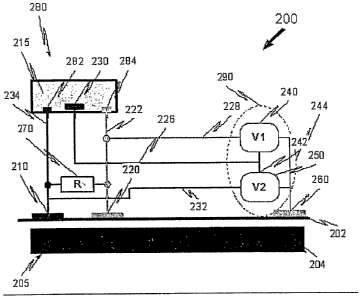
Reference is now made to Fig. 2C, which is a simplified schematic illustration
of
a sensing apparatus 200, in accordance with another embodiment of the present
invention.
The sensing apparatus 200 is used to sense at least one parameter of an
entity.
Apparatus 200 comprises two surface electrodes, 210, 220 each having a contact
surface
adapted to be placed on a surface 202 of the entity at corresponding at least
two separate
locations and further adapted to conduct electrical signals over a period of
time from the
two separate locations. The two surface electrodes are adapted to sense at
least one
characteristic of a current source of processes occurring under the surface of
the entity.
Apparatus 200 includes an electrolytic cell 280. The two surface electrodes
are
coupled to the electrolytic cell 280, which is isolated from the surface. The
cell 280
comprises an electrolyte 215, at least three cell electrodes 282, 284, 230 in
the
electrolyte, two of the cell electrodes 282, 284 in electrical communication
with two
surface electrodes 210, 220 of the at least two surface electrodes. The
electrolyte and
cell electrodes are housed within a housing, 285. At least one of the cell
electrodes is a
reference electrode 230, not directly connected to surface 202.
The electrolytic cell electrodes 282 and 284 are adapted to be polarized
responsive to the electrical signals so as to generate an electrolytic
reaction. The
CA 02644620 2008-09-02
WO 2007/099522 PCT/IL2006/000284
-19-
reaction induces polarization of the electrodes 282, 284 so as to provide at
least one
electrical output corresponding to the electrical signals.
Apparatus 200 further comprises a measuring unit 290, connected to at least
two
of the cell electrodes 282, 284, 230, adapted to measure the at least one
electrical output
from at least one of the two electrodes so as to sense the at least one
parameter.
In some embodiments, surface 202 is part of a biological entity 205,
comprising
surface 202 and sub-surface layers 204.
In some embodiments, the non-invasive apparatus 200 fiirther comprises a
shunting unit 270 adapted to provide a shunting resistance, wherein the
shunting unit is
connected to two of the at least two surface electrodes, 210, 220 and is
electrically in
parallel to the surface 202. In some embodiments, the shunting unit comprises
at least
one resistor or similar device. In some fiuther embodiments, the shunting
resistance is at
least 2 KOlun (KS2).
In some embodiments, the shunting resistance is preferably similar or equal to
the surface resistance. The shunting resistance is employed to reduce or
eliminate
system noise. In some cases, the system noise is static electricity,
piezoelectricity and
tribo-electicity of the skin. All body sources cause voltage and currents
perturbations
between working electrodes, yet at the same time all surrounding electro-
magnetic noise
and static electricity causes high voltage between the ground surface
electrode 260 and
surface electrodes 210, 220. For the neutralization of these noise effects in
this
invention, appropriate shunting and/or filtering units may be employed, such
as
unit 270.
Electrodes 210, 220 are at two separate locations, which are at least 5 mm
apart.
In some cases, the two separate locations are at least 8 rmn apart. In farther
cases, the
two separate locations are at least 10 mm apart. A minimal distance is
required to
prevent interference and electrical interactions between the electrodes.
In some embodiments, the contact surface of electrodes 210 and 220 is at least
0.5 cm2 each. In some cases, it is at least 1 cm2, in otlzer cases is at least
2 cm2. In some
embodiments, the exterior surface is at least 20 cm2. The actual impedance
between the
body interior resistance and the surface electrodes 210, 220 is minimal due to
relatively
wide electrode area of at least 0.1 cm2. hi sharp contrast, the size of the
acupuncture
points is typically less than 0.03cm2.
CA 02644620 2008-09-02
WO 2007/099522 PCT/IL2006/000284
-20-
In some applications of the present invention, electrodes have a surface area
of
0.25cm2 and are used for sensing signals in rats. Electrodes having a contact
surface of
around 1-4cm2 are used for sensing signals in humans. The materials of the
cell
electrodes in Figs. 2A and 2C are similar or identical.
In other embodiments at least one of the at least two surface electrodes is a
ground electrode 260.
In some cases, the reference electrode 230 provides a standard potential of
electrolyte 215 to measuring unit 290.
The apparatus 200 is often used to sense an activity in a mammal. Typically,
the
unit measures activities occurring under the skin of the mammal. Apparatus 200
of this
invention is typically used to measure a current under the skin of the mammal
and/or a
change in current under the skin of the mammal.
In some embodiments, the entity is selected from a biological entity, a
structural
entity, a geological entity, a chemical entity and a material entity.
In some embodiments, measuring unit 290 comprises at least one of a voltmeter,
an A/D converter, oscilloscope and a data acquisition card connected to a
computer or
processor.
The measuring unit is used to sense at least one electrical output. The output
may be selected from a voltage, a current and a resistance or a combination
thereof. In
some cases, the current is at least one of a direct current and alternating
current. The
alternating current typically has a frequency range of 0-100 MHz (megahertz).
Measuring unit 290 of apparatus 200 is adapted to measure the at least one
electrical output, which may be selected from:
a differential signal between at least one of the cell electrodes 282, 284
and the counter electrode 230; and
a differential signal between two of the cell electrodes 282, 284;
a differential signal between at least one of the cell electrodes 282, 284,
230 and at least one of the surface electrodes 210, 220, 260.
See Figs. 8-10, 16A-16C, and Example 2 hereinbelow for furtlier details.
Measuring unit 290 coniprises, in some cases, two measuring devices 240, 250
for measuring signals associated with each cell electrode 284 and 282
respectively.
CA 02644620 2008-09-02
WO 2007/099522 PCT/IL2006/000284
-21-
The units and system described herein may be applied for monitoring the
current
that is accompanied with metabolite flow in electrically active and
electrically inactive
cells under the surface of an entity.
An additional important feature is that ratio of area of skin part electrode
and
electro-chemical cell part of the electrode should be at least one-two orders.
Small areas
of electrode parts which are inside electro-chemical cells provide a small
capacitance
that allows detection of the high frequency signal.
Impedance between body interior and slcin electrode is minimal due to
relatively
wide electrode area at least 0.1 cm2. The characteristic size of the
acupuncture points is
about 1-2mm in diameter, therefore their area is one order less then 0.1cm2.
Important
to mention that for the most applications, even larger electrodes may be used:
0.25cm2
for rat sensor, 1-4cm2 for human sensor.
Input impedance of at least three cell electrodes is typically about lkOhm,
which
is less then characteristic impedance of the skin which approximately 5-30
kOhm. This
arrangement allows for passing of currents through the electrolytic cell.
These currents
may be quantified by determining/measuring polarization occurring in the cell
at the
electrodes.
Comparison of the electrode potential of at least one cell electrode 282, 284
versus the reference electrode 230 allows estimation of redox potential of
metabolic
processes inside the body.
It is important to mention that there is natural resonance of the
hydrodynamic,
electro-kinetic and electro-capillary processes in the body. These are
exemplified, but
not limited to, biological processes occurring under the skin. These processes
may be in
blood vessels, interstitial fluid and inside the cells. Resonance is a natural
property of
any living system including bio-layers. Such resonance provides a decrease of
the
metabolic transport losses. It leads to peristaltic activity, brain waves and
similar
synchronized directional processes. As a result of such self organization and
synchronization processes, there is a concomitant increase of integrated
current
densities. These current sources are the focus of our measurements in the
present
invention, which are measured by apparatus 100, 200A, 200 and 300
(respectively
Figs. 1, 2 and 3) and in the methods of Figs. 8-10 and in Examples 1-3
hereinbelow.
It is known that metabolite transport takes place in all types of living
cells.
Consequently, all types of cells cause formation of concentration gradients of
CA 02644620 2008-09-02
WO 2007/099522 PCT/IL2006/000284
-22-
metabolites and related metabolic products. This, in turn, leads to related
electro-
chemical and electro-kinetic processes. These processes provide changes in
current and
potential and hence, these changes may be measured and characterized.
In blood, lymph and interstitial fluid transport systems, fluid dynamic
movement
induce changes in local concentrations and related electro-chemical and
electro-kinetic
processes. These processes provide changes in current and potential and hence,
these
changes may be measured and characterized.
However, in small vessels, such as capillaries, the mean distance between
capillaries is about 50 micron. Furthermore a typical cell size is 1-100
micron. Since the
size of the surface electrodes 210, 220 and 260 is orders of magnitude greater
than that
of the capillaries and cells, the surface electrodes therefore, measure
integrated or group
activities of cells and/or capillaries. Effectively, this measurement provides
a smoothed
out statistical mean activity, which is measured with the units and systems of
the present
invention as described herein.
Thus, the systems of the present invention may be used to observe and track
responses to stimuli, perturbations and other disturbances induced to the body
or tissue.
The body or tissue response can be monitored. The frequency, amplitude and
spectral
characteristics and wave dynamics of the response can be analyzed and can be
used to
provide information regarding the status of the body or tissue. For example,
see
Figs. 15, 17, 18 and 19 hereinbelow.
In this context, any living system is a thermodynamically open system, which
can be stationary only if it corresponds to minimum in its Gibb's free energy.
Any local
perturbations are distributed at all possible degrees of freedom. In other
words, it means
that any local concentration or potential gradient can be detected in the
surrounding
tissue or organs. Thus, the present invention is directed to measuring redox
potential
electro-chemical reactions occurring inside a part of the body under
observation.
Furthermore, the systems of this invention are directed to monitoring the rate
and
distribution of metabolic processes by measuring their electrical current that
is
accompanied witli metabolism of electrically active and electrically inactive
cells.
Reference is now made to Fig. 3, which is a siinplified schematic illustration
of
a non-invasive self-checking electrolytic sensing apparatus 300, in accordance
with an
embodiment of the present invention.
CA 02644620 2008-09-02
WO 2007/099522 PCT/IL2006/000284
-23-
Apparatus 300 comprises an electrolytic cell 325 substantially similar to
cel1280
of Fig. 2A. Apparatus 300 further comprises surface electrodes 310 and 320,
substantially similar to electrodes 210 and 220 of Fig. 2A. Shunting unit 340
is similar
to shunting uiut 270 of Fig. 2A. Apparatus 300 further comprises an
electrolyte-
checking module 375. The electrolyte-checlcing module comprises a first module
electrode 350 of a third material and a second module electrode 360 of a
fourth
material. The first and second module electrodes are in the electrolyte 315.
The third
and fourth materials are different. Apparatus 300 fiuther conlprises a module
measuring
unit 385 in electrical communication with the first and second module
electrodes 350,
360 and a resistance providing unit 370 connected to the first and second
module
electrodes 350, 360.
The module measuring unit 385 is adapted to measure at least one of:
a) a differential signal between the first and second module electrodes 350,
360; and
b) a differential signal between at least one of the first and second module
electrodes 350, 360 and the reference electrode 330.
The third material and the fourth material typically comprise a metallic alloy
or
metal. Typically there is a difference in composition of the third and fourth
material so
as to provide a small potential difference (see Exainple 3 hereinbelow).
Fig. 4 is a siinplified schematic illustration of a system 400.
System 400 comprises a wearable unit 420, an input device 410, a
microprocessor 430, an outputting device 440, a.public communication system,
such as
the internet 450 and a communication device such as a phone 460.
In some embodiments, wearable unit 420 consists of sensing apparatus 300 as
described in Fig. 3. In some embodiments, unit 420 may be combined witli other
types
of standard sensors, such as a thermal sensor 422, accelerometer 424, a
microphone (not
shown) or other sensors known in the art. In alternative embodiments, unit 420
is not
wearable.
Sensing elements 422, 424, a.nd unit 426 are typically connected to at least
one
apparatus 430 comprising at least one programmable microprocessor 432 and at
least
one ineinory 434. The apparatus may be close to or distant from the body,
having wired
or unwired connections therewith, as is known in the art, such as standard
existing
technology like Infra-red technology used for computers, ultrasound teclmology
used
CA 02644620 2008-09-02
WO 2007/099522 PCT/IL2006/000284
-24-
for home devices or any other known in the art. In addition, to input from the
sensing
system 420, the microprocessor can get additional input from one or more
inputting
devices 410, which are located near to or distant from wearable unit 420. The
inputting
device 410 can be used for inserting personal information like time, dosage
and kind of
medication, supplement or food intake; necessary results from laboratory or
ambulatory
examination; correction of output regimen and format, etc.
In some embodiments, the apparatus 426 comprises at least two electrodes, for
placing on a surface of a body. In some embodiments, the electrodes may be in
a
bracelet or watch arrangement, may be in pads or in a waistcoat, trousers or
any other
piece of clothing, footwear, headwear, jewelry, bedclothes, or the like. In
other
embodiments, the electrodes may be in a stand alone device.
Microprocessor 430 may be replaced by any other type of computer having a
processor 432 and at least one memory 434.
The output of the microprocessor 430 may be communicated to any outputting
device 440 located near to or distant from the sensors 440, or can be
transmitted to a
cellular phone 460 or to the internet 450, interactive TV (not shown) or to
any other
communication system known in the art.
The measuring/sensing units (with reference to the figures) described herein
may be employed to measure a large number of different parameters, such as,
but not
limited to, those described herein.
System 400 may be used for many different applications, such as monitoring
metabolism and body reactions or processes. Some examples include, but are not
limited to:
a) Glucose level monitoring (for further details see Figs. 16A-16C, 6,7).
For glucose monitoring, the wearable unit 420 comprises a sensing apparatus
200 or 300 and a sweat detector known in the art.
Note: here and below the apparatus 300 can, for some applications, be replaced
by simpler apparatus such as apparatus 100 and apparatus 200. In some
embodiments,
apparatus 300 is preferred to the simpler apparatus as it is fully self-
contained. In some
cases, apparatus 300 can be replaced by its multi-array modification 500.
CA 02644620 2008-09-02
WO 2007/099522 PCT/IL2006/000284
- 25 -
b) Limb metabolism or limb blood sLip-ply monitoring(exemplified in more
detail in Fig. 17):
For monitoring limb metabolism, wearable unit 420 comprises a sensing
apparatus 200, 200A or 300, as well as a thermo sensor- main and optionally a
pulse
wave sensor (acoustic sensor - for each measured limb).
c) Wireless ECG
For wireless ECG monitoring, five sensing apparatus 200, 200A or 300- one
near heart and four for all limbs are required. It may be possible to decrease
this number
to 1 or 2 in the future.
In addition, it is possible to have a contact less sensor of any electrical or
magnetic field. In addition, it is possible to add another sensor of a totally
passive
chemical material (nano-technology powder) which will not have direct contact
with the
skin, but will provide high impedance and will reduce the danger of having a
stroke due
to adsorption of the increased electro-magnetic energy. Additionally, ECG
monitoring
device could be combined with a bio-feedback "relaxometer" (described
hereinbelow)
for monitoring a nervous system state in parallel to cardiovascular state.
d) Blood pressure monitoring
For monitoring of blood pressure, the monitoring unit comprises at least one
sensing apparatus 300 combined with pulse wave sensor, and optionally a
thermosensor
or acoustic sensor.
e) Blood viscosity monitoring
For blood viscosity monitoring, the monitoring unit comprises, at least one
sensing apparatus 300 and at least two pulse wave sensors.
f) Peri-pheral nervous system (PNS) monitoring (including measuring
sympathetic/parasyMpathetic index) monitoring
For PNS monitoring, the monitoring unit comprises, for example at least one
sensing apparatus 300.
CA 02644620 2008-09-02
WO 2007/099522 PCT/IL2006/000284
-26-
g) Central nervous system (CNS) monitoring
For CNS monitoring, the monitoring unit comprises for example at least several
sensing units 300 and at least one acoustical sensor for placing on the scalp.
It is
preferable to use combined nervous system monitoring employing f) and g)
together.
h) Local metabolism monitoring, organ/tissue fiuictional monitoring
(exemplified in more detail in Figs. 17, 18 and 19).
For local metabolism monitoring, organ/tissue fiuictional monitoring apparatus
comprises at least one sensing apparatus 300 or multi-array 500.
Inflammation can be observed in addition to other metabolic processes as it is
accompanied with metabolism change. In order to make a monitor, at least one
sensing
Apparatus 300 is employed, though multi-arrays 500 are also envisaged.
The sensing apparatus 300, 500 can be combined with thermosensors, pulse
sensors, acoustic sensors or any other physiological sensors known in the art.
i) Cancer diagnostic monitoring (CDM) (exemplified in more detail in
Fig. 18).
For cancer diagnostic monitoring, similar to local metabolism monitoring, the
monitoring unit comprises at least one sensing apparatus 300 or multi-array
500, which
can be combined with thermosensors, pulse sensors and acoustic sensors.
CDM may include cancer/tumor size estimation; characterization of a tumor or
cancer is metastatic or not, polymorphic or monoclonal; estimation of its
growth
dynamics and other similar applications of the art.
j) Drug and active material metabolism monitoring (exemplified in more detail
in Fig. 19):
For drug and active material metabolism monitoring, the wearable unit 420
comprises one or more sensing apparatus 300 or nlulti-arrays 500 placed
according to
where and how wide the stimuli work. Unit 420 can be combined witli CNS & PNS
monitoring, local metabolism monitoring and cardio-vascular monitoring. Unit
420 can
also be combined with therinosensors, pulse sensors and acoustic sensors.
Combiuiation
of sensing apparatus 300, 500 together with CNS monitoring wearing unit
described
above allows the tracking the blood brain barrier penetration.
CA 02644620 2008-09-02
WO 2007/099522 PCT/IL2006/000284
-27-
k. Psychological detector, lie detector (exemplified in more detail in Fig.
15).
The apparatus may be applied to check psychological status, lie detection,
checking self-confidence with respect to certain decisions or thoughts and
psycho-
immune status. The apparatus can also be used to check "search activity" to
improve
treatment or surgery. It can further be used for self training. The apparatus
can further
be applied to check psycho-status of people having high responsibility work
(pilots,
nuclear station workers etc) and can be used during their training. The
apparatus can be
used for potential terrorist detection. These kinds of applications are termed
herein
"psychological monitoring"..
For "psychological monitoring" the wearable unit 420 typically comprises at
least one sensing apparatus 300 probably combined with multi-array 500. The
apparatus is placed on the body of a person in accordance with the type of
response to
be detected, in response to one or more stimuli under observation. Sensing
Apparatus
300 ca.n be combined with CNS & PNS monitoring, local metabolism monitoring
and
cardio-vascular monitoring. Additionally, the apparatus can be combined with
tliermosensors, pulse sensors, acoustic sensors, optotrack, or any other
sensors known in
the art.
1) Chakra, acupuncture, meridian dia ng ostics
For chakra, acupuncture and meridian diagnostic monitoring, the inodule
420 may comprise a multi-array measuring apparatus 500, which can be combined
for example with acoustic sensors, thermosensors and pulse sensors.
It should be noted that all of the above medical or physiological applications
can
be closed as a bio-feedback devices for self use, medical diagnostic devices
or life guard
with alarm for the different physiological systems.
m) Material quality check and corrosion detection. Applications for geology
and
earthquake early detection
For material properties, corrosion detection or applications in geology and
earth
quake at least on apparatus 300 may be used. For these non-biological
applications
the materials and electrolyte solution may be adapted to the measured
substances.
CA 02644620 2008-09-02
WO 2007/099522 PCT/IL2006/000284
- 28 -
The sensing apparatus can be used in geology including earthquake early
detection, material quality check, estimating life span for old buildings.
This takes into
account that inside the entity there are reversible and/or irreversible
processes taking
place that are accompanied by electrolytes, solid mass, liquid and/or gaseous
flows
which induce electrical perturbations, detectable by the apparatus of the
present
invention.
For researching of the geochemical processes that take place in liydro-thermal
solutions or in the mineralization zones, electro-chemical cells, such as
those depicted
in Fig. 2 and Fig. 3 can be used. In some cases, the electrolytic cell
comprises copper
electrodes in a sulfate solution, in combination with different types of metal
electrodes
for insertion into earth or rock, accelerometers and antenna devices. Such
combinations
allow the measurement of galvanic currents parameters and variability thereof.
In some cases, these geochemical processes are accompanied with processes of
stalactites and stalagmites growths, mine formation, and also precursor
processes of
earthquakes and eruptions.
Reference is now made to Fig. 5A, which is a simplified schematic illustration
of a vertical cross-section of a non-invasive electrolytic cell array 500 in
accordance
with an embodiment of the present invention. Array 500 comprises an
electrolytic cell
502 having an electrolyte 504, a reference electrode 550 and a plurality of
cell
electrodes 510. The plurality of cell electrodes 510 are all immersed in the
same cell.
This arrangement enables both the quenching of noise and multidimensional
measurement. Similarly to electrolytic cells of Figs. 2 and 3), the cell
electrodes 510
may act as measuring and/or counter electrodes and have an outer surface made
from
the same material, which is not shown in this figure and electrolyte cell part
(560, 510,
550).
Advantageous properties of arrays include, for example, but are not limited
to:
a) mutual inter-polarization of each pair of electrodes 510 and of all of the
electrodes together;
b) applying several relatively wide skin electrodes 510 to a surface decreases
the
total system resistance, and therefore improves signal to noise ratio; and
c) simultaneous measurement of each of several electrodes versus the same
reference electrode 550 enables one to obtain more detailed physiological
parameters
inonitoring in time and in space with a higher accuracy.
CA 02644620 2008-09-02
WO 2007/099522 PCT/IL2006/000284
-29-
Fig. 5B is a simplified schematic illustration of a horizontal cross-section
of a
non-invasive electrolytic cell 500 in accordance with an embodiment of the
present
invention. It can be seen that the array of cell electrodes 510 is organized
around the
central reference electrode 550.
Fig. 6 shows schematic depictions of a glucose monitoring device, viewed from
the top, in cross-section and from the bottom, respectively, according to an
embodiment
of the present invention;
Referring to Fig. 6, there is shown a first embodiment of the preseiit
invention,
adapted for glucose deterniination/monitoring, illustrated by a wrist watch or
wristlet
comprising three types of sensors: pulse-wave sensors 6a and 6b based on piezo-
electrical sensors (Samsung or Motorola), biocompatible electrodes,
biocompatible
electrodes 7 made from pure silver 99.99%, and additional biocompatible
electrodes 8a
and 8b and estimating the acidity thereof, made from pure silver and silver-
platinum
alloys 90% and 10% respectively.
The device comprises the following electronics: a keyboard 1, a body 2 with a
display 3 and an electronic block 4. The keyboard 1 is supplied with a
connector 5 to
allow connection of a programmed cartridge, for example a home computer,
cellular
phone, palm-sized electronic notebook, etc (not shown). The body 2
incorporates the
pulse-wave sensors 6a and 6b, biocompatible electrodes 7, and additional
biocompatible electrodes 8a and 8b.
Electronic block 4 is supplied with an antenna 9 and a connector 10 for
transferring data and/or an alarm signal through an external transmission-
corulection
unit (not shown), (e.g. telephone line, fax, the Internet) for sending such
data to a
physician.
The device also includes two thermometers 11a and llb for measuring the
patient's skin and the surrounding temperature, respectively, and a 3-
diemnsional
accelerometer 12 for measuring motion intensity or physical activity of the
hand (not
seen).
Fig. 7 is a simplified bloclc-diagram showing the operating logic of the
glucose
monitoring device of Fig. 6 and showing the operative connections between
coiuponents of the device.
The following components are shown and labeled as indicated:
CA 02644620 2008-09-02
WO 2007/099522 PCT/IL2006/000284
-30-
= The two pulse-wave sensors 6a and 6b (PWSl and PWS2), which are connected to
a microprocessor (MP 6).
= three electrodes 7(El l, El 2 and El_3), where electrodes El 1, El 2 are
electrochemically connected to electrode El 3, which is a reference electrode
(not
seen in Figs. 1-6 as it is inside the electronic block 4). The three
electrodes 7(El 1,
El 2 and El 3) are connected to three voltmeters V2, V3 and V4, respectively.
In
order to measure DC and AC voltages it is necessary to use the two separate
voltmeters. Tllerefore the signal from the El_1 goes to V 1 to measure
acidity, to V2
to measure DC and to V3 to measure AC.
= The two perspiration measuring electrodes 8a and 8b (AdEI_1 and AdEI 2),
which
are each connected with a voltmeter (V 1, V2), respectively;
= The 3-dimensional accelerometer 12 (Acc).
= Two thermometers lla and llb (T-1 and T-2) for measuring slcin and
surrounding
temperature, respectively.
= Four microprocessors (MP1, MP2, MP3, MP4); and the programmed
microprocessor MP6 connected to the keyboard 1; and a processor, MP5, with
memory M connected thereto; and having a charge-connector unit and alarm
system.
Note, the voltmeters and microprocessors referred to herein are not seen in
Fig. 6 and so are not given reference numerals (merely labels as seen in Fig.
7),
however, they are located within the electronic block 4.
The microprocessor MP1 is connected with PWS1 and it analyzes pulse-wave
spectral characteristics using a standard mathematical software program
package (e.g.
Matlab or other software). The microprocessor MP2 is connected to PWS1, PWS2
and
a timer/clock, and it measures a pulse wave propagation velocity and heart
rate. The
microprocessor MP4 is connected to PWS2 and it analyzes a pulse wave spectrum,
for
example using Matlab. Examples of results of such analysis are shown in
Figures 16A-
16C. Generally, the whole process data acquisition, processing and outputting
is
described in more details by Figures 4, 8, 9, 10.
The above microprocessors MP1, MP2 and MP4 are connected with a
programmed microprocessor MP5 having a display. The potential difference
between
electrodes 8a and 8b (AdE1-1 and AdEI-2) is proportional to the perspiration's
acidity.
CA 02644620 2008-09-02
WO 2007/099522 PCT/IL2006/000284
-31 -
Fig. 8 is a simplified flowchart 800 of a method for sensing and determining
at
least one parameter of an entity according to an embodiment of the present
invention.
In a first step, 805, a unit such as Apparatus 300 is placed on a surface so
as to
complete a circuit. The unit is typically part as a system such as system 400
of Fig. 4.
The completion of the circuit induces an electrolytic reaction in an
electrolytic cell, such
as ce11280 or cell 325.
Thereafter, in a measuring step 810, a change in at least one measurable
electrical parameter is measured by measuring unit 290, 375.
The measurements from step 810 are then stored in at least one memory in
storing step 815. The memory for example, is memory 434.
In parallel to step 815, the data is transferred in a transferring step 850
for
further analysis and to trend analysis step 855 (see Fig. 10 for further
details).
In a first checking step 820, it is determined whether the time elapsed is
greater
than a predetermined short capture time Ctshort. If negative, the system
continues to
measure the parameters in measuring step 810. If affirmative, the system
proceeds onto
extracting step 825. In extracting step 825, the values of that parameter for
time=
Ctshort are extracted. This checking step can be applied to a large nunlber of
parameters and to different predetermined capture times.
In a longer loop, it is determined whetlier the time elapsed is greater than a
predetermined long capture time the time Ctlong. If affirmative, the system
proceeds to
step 845 and the capture timing is started again.
Thereafter in a processing step 830, the values of that parameter for the
predetermined period of time, whether long or short are processed. Further
details of
this step are shown in Figs. 9-10.
The outputs of the processed data of step 830 are then stored in storing step
835
in at least one memory, such as memory 434.
In an outputting step 840, the results from step 830 are outputted to at least
one
of device 440, phone 460 and device 410. Additionally or alternatively, the
output may
be stored or relayed to a remote location.
In a second checlcing step 860, the output results from step 840 are checked
to
see if they fall within a predetermined range. If affimlative, the results are
displayed in
display step 880. If negative, an alaim is activated in an activating alarm
step 865.
CA 02644620 2008-09-02
WO 2007/099522 PCT/IL2006/000284
-32-
Thereafter in a displaying step 870, the out of range results are displayed on
one
or more displays 440 (Fig. 4).
Reference is now made to Fig. 9, which is a simplified flowchart 935 showing
further details of step 830 of Fig. 8, of a method for sensing and determining
at least one
paraineter of an entity, according to an embodiment of the present invention.
In a signal processing step 905, a number of measurements taken over a period
time for a certain parameter are processed. The time period is determined for
each
parameter and type of application independently according to the specific time
constants
for that parameter and application. The time period may be very short, such as
a number
of seconds up to a continuous measurement over a long period of time.
The output of step 905 is fed into one or more models in a second processing
step 910. This step is a model choosing step in which the output of step 905
is
compared to one or more models to find a best model.
In a calculating step 920, the best model is applied to the output of step 905
so
as to provide a second output.
In an integrating step 930, the second output is fed into a second model or
algorithm and a third output is produced.
In a checking step 940, the fit of the third output is compared to a set
range. If
the fit is sufficiently good, then the model is accepted. If not, then the
model is
corrected in step 950 and further data is introduced to the model in step 905.
Flowchart 935 may comprise one or more self-learning neural networlc
algorithins known in the art.
Fig. 10 is a simplified flowchart 1000 showing further details of step 855,
for
trend analysis according to an embodiment of the present invention.
In a first extracting step 1010, data (long capture time reference, (LCR))
accumulated over a long capture time Ctlong is extracted from the system
memory.
In a processing step 1020, the data of long capture parameter (LCP) from
memory accumulated over Ctlong is processed to analyze at least one trend over
time
period Ctlong or over a longer time period than Ctlong.
In a comparing step 1030, LCP is compared with LCR and a conlparison result
(CR) is outputted.
In a storage step 1040, CR is stored in one or more system memories.
CA 02644620 2008-09-02
WO 2007/099522 PCT/IL2006/000284
- 33 -
In a checlcing step 1050, the CR is checked to see if it fits within a desired
range
or limits. If the result for CR is out of range, then the system proceeds to a
waiting
step 1060, in which the system waits for a long capture time Ctlong until fi.u-
ther data is
accumulated.
If the CR fits the model then, then the system proceeds to step data
accuinulation
step 1070. In this step the data is accumulated in a trend model and/or trend
database
store.
In a model correction step 1090, the accumulated data from step 1070 is
applied
to one or more models so as to impact on the existing model or models.
In parallel, in an alarm step 1080, an alarm is set off if the accumulated
data
shows a significant anomaly.
Fig. 11 is a simplified diagrain illustrating the measurement principles of a
pulse
wave and its propagation rate used in the present invention;
With reference to Fig. 11, the principles of pulse wave measurements use the
following principles:
1. The rate of movement of the blood can be estimated by the rate of pulse
wave-
propagation between sensors 6a and 6b.
2. The blood flow is proportional to the cross-section of arteries and the
velocity of
the blood.
3. Blood viscosity affects the shape of the pulse waves, the rate of their
propagation
and the pulse wave spectrum.
The following data are supplied to the programmed microprocessors from the
various sensors:
1. Pulse wave area from PWS1,
2. Pulse wave spectrutn from PWS1,
3. Pulse wave area from PWS2,
4. Pulse wave spectrutn from PWS2,
5. Pulse wave propagation velocity,
6. Heart rate,
7. Indication of existence of perspiration, and
8. Acidity of perspiration.
CA 02644620 2008-09-02
WO 2007/099522 PCT/IL2006/000284
-34-
For calibration purposes, the first data are compared in the prograinmed
microprocessor MP5 with parameters (i.e. glucose level, blood pressure, heart
rate, etc.)
that were recorded in the processor's memory M during an oral glucose
tolerance test
(OGTT) and/or during an electrocardiogram (ECG) stress test. The results of
such a
calibration are input into an individual "mathematical model" resulting from
an
individual calibration witli neural network software. Similar neural network
software is
used to estimate the following important parameters:
1. Blood glucose level,
2. Heart rate,
3. Blood flow,
4. Blood pressure,
5. Blood viscosity (which may be affected by dehydration).
The programmed microprocessor MP5 displays selected parameters on the
display 3. It is connected with a processor P that can produce an alarm if
selected
parameters are beyond predetermined limits, which depend on the rate of change
of the
parameters.
The alarm (and parameters) may be transmitted through a cellular telephone or
otlier means of communication. All of the parameters are periodically recorded
in the
memory M in case any deviations, for example, they may be transmitted daily
into the
computer of a physician, medical center, clinic, etc, through a separate
charge-
connection unit.
Fig. 12 is a graph showing the theoretical rate of glucose, absorption as
function
of blood glucose and insulin levels according to theoretical model estimation,
according
to an embodiment of the present invention.
In Figure 12, there is shown the change of the rate of cellular glucose
absorption
as a function of the blood glucose level at a range of insulin levels
(picomoles/ml). As it
can be seen, the rate of glucose absorption depends on glucose and insulin
blood level.
Additionally, one should mention that the maximal rate of glucose absorption
is
typically in a BGL range of 65 to 115 mg/dL, which corresponds to the maximal
stability of the glucose level and more particularly to the maxinlal motion
force and rate
of return to equilibrium (as seen in Figure 13).
CA 02644620 2008-09-02
WO 2007/099522 PCT/IL2006/000284
-35-
Fig. 13 is a theoretical derivative rate of glucose absorption which reflects
restoration rate of the metabolic equilibrium, or bio-stability, according to
an
embodiment of the present invention.
Preliminary examination of the other components of the device consisted of
checking pulse-wave and bio-electricity diagnostics. The above- described
theoretical
basis of such diagnostics is explained with reference to Figs. 12-14. Data for
Figs. 12
and 13 were generated from the Michaelis-Menten equation and the data for Fig.
14
were generated from the Lipman equation and electro-capillary curves.
The change of the rate of cellular glucose absorption as a function of the
blood
glucose level at a range of insulin levels (picomoles/ml), is shown in Fig.
12. The rate of
glucose absorption depends on glucose and insulin blood level. The dominant
parameter
of any living system is metabolism, which includes in particular the
equilibrium
between carboliydrate metabolism and oxygen/carbon dioxide use and production.
Fig. 14 shows the results of a theoretical model depicting the Gibb's free
energy
of healthy and cancer cells, according to an embodiment of the present
invention;
The function of Gibb's energy of healthy cells is indicated by diamond symbols
while Gibb's energy for cancer cells is indicated by square symbols. The
relative Gibbs
energy is relative to the average Gibbs energy of the cells; and the relative
intensity of
metabolism is relative to the 50% level of the normal basic inetabolism value.
Metabolism measurements, which are measurable using apparatus 300, 500 of the
present invention, can provide estimation of cellular Gibb's energy and thus
can provide
important information in.the treatment of cancer.
The Gibb's energy is dependent on the relative intensity of the metabolism. It
shows that ih the condition of both a metabolism that is too low or too high,
the Gibbs
energy of cancer cells is lower than that of healthy cells. Under this
condition the rate of
cancer cell division may be much higher than in healthy cells.
Furthermore, the separation between the curves in Fig. 14 shows that there is
a
Gibb's energy difference between cancer and healthy cells which allows the
estimation
of polymorphism of the cancer cells. The tendency for polymoiphism is
proportional to
the difference in the Gibb's energy between the cancer cells and the healthy
cells.
Cancer polymorphism itself is a very important property of the cancer cells
which
directly affects treatment protocol decisions and the potential effectiveness
of cancer
treatment.
CA 02644620 2008-09-02
WO 2007/099522 PCT/IL2006/000284
-36-
Fig. 15 is a graph showing experimental data generated by a sensing apparatus
100 Fig. 1 of the present invention adapted to function as a "psychological
monitoring",
according to an embodiment of the present invention.
This figure shows the results of a further experiment measured by sensing unit
described in Fig. 1. This experiment based on theoretical model of brain body
analog
circuit described in details by Fig. 20.
This experiment involved two female volunteers (volunteer AM, aged 63 and
volunteer LG, aged 56). The each volunteer was connected to the sensing
apparatus
described in details in Fig. 1 and arranged as a bracelet device on the right
hand, in the
supine position to avoid uncontrolled movement. During the measurements the
volunteer was asked to recall different situations from life, including: (a)
thinking about
first pregnancy, (b) thinking about another person, (c) meditation and (d)
playing with
grandchildren.
The time at which these thoughts were suggested are shown by vertical arrows
on the graphs of Figure 15A-B. It can be seen that typically after a brief
delay of a few
seconds, there is a clear change in the voltage characteristics such as
amplitude or
spectral characteristics. Such change shows that such measurements (including
DC and
low frequency AC together with high frequency AC) are capable of indicating a
response to various psycho-emotional stimuli. Such measurements therefore have
potential applications in lie detector machines and to psycho-immune
measurements or
self-confidence monitoring.
A. Imagination task in volunteer AM asked to imagine a) first pregnancy; b) to
think
about person A; c) imaging playing with smaller grandchild; d) recall
successful
meditation; e) think about person B.
B. Imagination task in volunteer LG asked to thinlc about a) person A; b)
person B.
Important to mention, that we performed similar "imagination experiments" with
electrode pairs described in Fig. 1 applied to different body parts, for
example, chest,
abdomen area, under the liver, thyroid, on head, etc. These experiinents
sliowed that
different body parts have different magnitude and character of reaction to
different
lcinds of mental activity. This multi-electrode body mapping device can be a
real basis
for the psycho-immune status detector, lie detector, self-confidence detector
or multi-
level real time diagnostic device for organ functioning as a result of any
kind of
CA 02644620 2008-09-02
WO 2007/099522 PCT/IL2006/000284
-37-
physical or mental activity. This research can put light of body mind
interconnection
and inter-influence.
Additionally to organ functional diagnostics, the same measuring system
applied
on classically defined charkas places can serve as a functional charka
diagnostics as
itself and as related to different lcinds of activities. Defined in Indian,
Tibetian or
Chinese traditional medicine charkas and marmas places are anatomical places
characterized by high density of bio-fluids flows and/or correspondently high
density of
energy transform and concentration gradients. Coniparative anatomical analysis
shows
that most of anatomical elements forming these flows like blood vessels,
lyinph vessels,
nerves, etc are forming spirals, because it corresponds to minimization of
losses and
also feat the requirement of maximally equal nutrient and gases supply.
Fig. 16A-16D are graphs showing experimental data generated by a sensing
apparatus 200 of Fig. 2 for detecting glucose levels in different patients,
according to an
embodiment of the present invention.
In Fig. 16A, examples of raw data are shown and corresponding spectral
analysis different blood glucose levels in humans. The first column shows
voltage of
first electrode and second electrode, where two electrodes were placed along
the hand
vein flow. Blood glucose level (BGL) was estimated by standard AccuCheckTM
First row: Data taken from normal person with BGL = 75 mg/dL
Second row: Data taken from the same person after dinner with BGL = 144
mg/dL
Third row: Data taken from diabetic patient with BGL = 111 mg/dL
Forth row: Data taken from the same diabetic patient with BGL = 173 mg/dL
In this figure, changes of voltage and voltage spectral characteristics of
changes
in the blood glucose level are displayed.
In Fig. 16B, there are shown examples of raw data and spectral analysis from
an
anestlletized male rat (weight 450 g.) for different blood glucose levels. The
first
colunm shows voltage of a first electrode and of a second electrode, where two
electrodes were placed along the tail vein flow. Blood glucose level (BGL) was
estimated by standard AccuCheck (Roche, Mannheim, Geirnany). For change in BGL
the rat was injected IP with glucose/insulin.
First row: Data talcen from anesthetized rat with BGL = 146 mg/dL
Second row: Data taken from the same anesthetized rat with BGL = 19 mg/dL
CA 02644620 2008-09-02
WO 2007/099522 PCT/IL2006/000284
-38-
Similar to human data in rats one can also observe clear changes of voltage
and
its spectral characteristics with changes in the blood glucose level.
Fig. 16C shows the results of the following experiment: GlucoSat sensors were
connected to an anesthetized rat and the signal was record for two hours
detecting a
blood glucose level of from 116 mg/dL to 318 mg/dL.
In this figure, as an example, four calculated GlucoSat parameters were
plotted
as a function of blood glucose level measured by AccuCheck (Roche, Mannheim,
Gennany). For each graph, correlation coefficients were calculated, as well as
p-value.
Most correlations had a fit of close to 0.9, and all of them were significant
at
least at level 0.0000 1 (highly significant).
This model takes in account more then these four parameters, thus enabling to
increase the accuracy and reliability even further.
Fig. 17 shows graphs displaying experimental data generated by a sensing unit
100 of Fig. 1 of the present invention wherein the device is used to
investigate limb
metabolism.
Fig. 17 shows the results of different voltage measurements, produced by the
electrodes 108, 112 of the sensing unit 100 of Fig. 1. One wearable unit 420
of Fig. 4
comprising sensing apparatus 100, worn on each of all four limbs and
corresponding
DC and low and high frequency AC voltage changes were measured during contact
of a
ha.nd to the left leg by an assistant (at about 65 seconds into the
experiment); and later
(at about 180 seconds into the experiment) witli the volunteer heating his own
hands
using thought/imagination.
The mean voltage value measured as a result of limb metabolism itself carries
important information about general blood supply and mean limb metabolism
value. It
can be used as a diagnostic of stagnation and swelling, peripheral arterial or
vein
disorders, or otliers metabolic activities, disorders or dysfunctions.
The dynamic changes of the measured signal pattern as a result of a reaction
to
any applied stimuli to an entity may be used as a functional diagnostic,
reflecting not
only static properties, as a mentioned hereinabove, but also dynalliic
properties, such as
ability to react, to return to homeostasis or steady state values, hysteretic
characteristics
and otlzer dynamic phenomena.
CA 02644620 2008-09-02
WO 2007/099522 PCT/IL2006/000284
-39-
The perturbations seen in the figures are as a result of different applied
stimuli,
which can be used to demonstrate metabolic activities, disorders and
dysfunctions,
related to metabolism and blood flow change in the limbs.
The apparatus can be used for bio-feedback and for diagnostics. Furthermore,
this figure shows new results that indicate that metabolism and reaction to
the stimuli
applied to one limb significantly affects all the other limbs. Furthermore,
these
experimental results support a recently developed theory that there is a
coordinated
interconnection between the limbs. This, in itself, has an enormous importance
for the
functional diagnostics and treatment of limbs in case of gangrene and
amputation
prevention, elimination of swelling, rehabilitation after injuries, functional
training after
amputation of one f the limbs and others.
Fig. 18 shows graphs exhibiting experimental data generated by a sensing
apparatus 100 of Fig. 1 the present invention for local metabolism disorder
diagnostics
(in this case - melanoma).
Here unit 420 comprising sensing apparatus 100 was worn on a portion of a 53
year old male patient having diseased skin with an affected metabolism. The
graph
shows dynamic voltage change during a bio-resonance electro-magnetic
treatment.
For the first three minutes of the measurements, the patient was working by
himself, i.e. using the device as a biofeedback system. At three minutes into
the
experiment, the patient fell asleep and an electro-magnetic resona.nce
treatinent began
wherein different resonance signals were used.
The change in voltage response seen in the curve of Fig. 18, at three minutes
into the experiment when the resonance treatment began, validates the
sensitivity of the
electrode measurements to a change in local metabolism caused by the
treatment. The
device further monitored the patient's metabolism parameters during
continuation of the
treatment, which was suspended temporarily between 28-31 minutes and after 39
minutes. Again, the electrodes measure changes in the patient's local
metabolism as
seen in the response change shown in Fig. 18 at those times.
Fig. 19 shows outputs prior to and after providing an entity with a nutrient
supplement, using a sensing apparatus 100 of Fig. 1 for determining some
aspects of
nutrient/supplement or drug metabolism, according to an embodiment of the
present
invention. Fig. 19 graplucally shows experimental data generated by the
present
invention as a nutrient/supplement or drug metabolism tracking system. During
this
CA 02644620 2008-09-02
WO 2007/099522 PCT/IL2006/000284
-40-
experiment, a 64 year-old male volunteer, took a nutrient supplement while the
surface
electrodes of apparatus 100 of the device were placed on his body at locations
at which
this supplement was expected to act.
There was a clear affect in the dynamic of mean voltage, in particular a 50mV
decrease, as a result of the supplement intake.
This indicates that the device can be used to track physiological changes in
the
body as a result of drug/supplement/food intake and thus it has application in
pharmaco-
dynamics, drug/supplement development, improvement of treatment protocols,
diet
programs and others.
Fig. 20 is a simplified flowchart 2000 showing postulated interactions between
the brain and body in a mammal in response to a stimulus, according to an
embodiment
of the present invention.
In a stimulus providing step 2010, an entity, such as a mammal is provided
with
one or more stimuli. The stimuli may be, for example, a physical, a chemical,
a
psychological or another stimulus. In some experiments, the stimulus is a
drug, a food
or other stimulus.
In a sensing step 2020, the mammal senses the stimulus. The sensing may
include use of one or more of the known six senses and sensing iilformation is
outputted
to the brain and to the body.
In a body processing step 2030, some cell, organelle, organ or body processes
ensue. For example, a muscle may contract, hair follicles may be erected, and
heart rate
and breathing rate may change.
In a body outputting step 2040, at least one output is affected. This output
may
be voluntary or involuntary. Examples of voluntary outputs include, but are
not limited
to, movement and speech. Involuntary outputs include reflexes, sweating,
blinking and
the like.
In a cognitive processing step 2050, in parallel to step 2030, the brain
processors
the sensing information from step 2020.
In a cognitive outputting step 2060, at least one cognitive output is
produced.
The output may include conscious and/or unconscious outputs. Conscious outputs
include tliouglits and emotions. Unconscious outputs include dreams and
phobias.
CA 02644620 2008-09-02
WO 2007/099522 PCT/IL2006/000284
-41-
As is shown in Fig. 20, there may be numerous interactions between cognitive
processing step 2050, body processing steps 2030, cognitive output step 2060
and body
output step 2040.
Fig. 21 is a simplified illustration of the outer surface layers including
(skin) of a
mammal. In Fig. 21, there is shown cross section of the normal skin that
contains
hypodermis, dermis and epidermis. Epidermis is relatively thin layer about 0.1-
0.2 mm
which content dead cells with skin fat and opened sweat gland and sebaceous
ducts.
The skin contains also hairs that lay under skin surface. Keratin, elastin and
hairs
have a semi-conductive properties and create voltage under applied deformation
or
mechanical stresses. Potential. formation also takes place between particles
of
epidemical layers.
Hair follicles and sebaceous glands such as sweat glands are dislocated inside
dermis and connected with blood vessels capillary network. These glands and
their
ducts act as arrector pilli form lines of increased conductivity between skin
surface and
internal tissue. Skin surface secretes about at least 500 ml/day of sweat that
contains
about 1% of mainly electrolyte and other substances.
Hypodermis includes fat tissue which improves skin thermo isolation
properties.
It is very important that dermis and hypodermis contains living cells
surrounded
by interstitial fluid. Therefore surface skin electrodes having relatively
wide area first of
all interact with interstitial liquid inside the body using lines of natural
increased
conductivity.
Moreover, skin surface can be also seen as a semi-penneable membrane through
wliich our body produces gas exchange with the surroundings.
Fig. 22 is a siinplified illustration of the action of a sensing apparatus 200
or 300
(Fig. 2 or 3) or in system 400 of Fig. 4 in measuring under-skin currents of a
mammal;
according to an embodiment of the present invention.
In any part of our body take place metabolic processes and corresponding
metabolite transport which includes, as it is shown in Fig. 21, blood and
lymph vessels
and also diffusion and convection transport in interstitial fluids and inside
cells.
There is always exists a concentration gradient inside tissue and between
tissues
and blood or lymph capillary vessels which needed for transport optimization.
According to Nernst equation, any concentration change always is accompanied
with
voltage change; in addition, any electrolyte motion can be seen as a current.
Therefore
CA 02644620 2008-09-02
WO 2007/099522 PCT/IL2006/000284
-42-
metabolite transport naturally cause bio-electricity part of which has to flow
through
applied to the skin our novel measuring systein.
In Fig. 22, it is schematically illustrated, some of the possible ways of
using a
sensing apparatus, such as, but not limited to 200, 200A, 300, or 500 applied
to the wrist
of person. Two surface electrodes, such as, but not limited to, electrodes
210, 220 are
applied on the skin surface in a bracelet manner (in this picture shown the
hand cross
section). The numbers in this figure correspond to the reference numerals of
Fig. 2,
wherein there is an electrolytic cell 280 filled with electrolyte 215 have two
working
electrodes 282, 284 and a reference electrode 230. Three electrolytic cell
electrodes 282,
284, 230 are connected further to measuring unit including device of voltage
measurement between worlcing electrode and reference electrode 240, 250.
Figs. 23A-23B are graphs of outputs relating to spontaneous muscle activity
recorded by apparatus 200, according to an embodiment of the present
invention.
Fig. 23 is an output relating to typical spontaneous muscle activity recorded
by
apparatus 200 from a person's right hand during the relaxation session.
In this experiment, a female volunteer (TM age 66) was lying on the mat
motionless while she was lead through a deep relaxation session by
professional yoga
teacher.
The lower line indicates the measured potential from first surface electrode,
while the upper line indicates measured potential from the second electrode.
The
measured signals were smoothed using standard Gaussian filter using Matlab
functions.
Fig. 23A shows measured activity during about 250 sec of the relaxation
experiment.
In Fig. 23B the typical spontaneous muscle activity is plotted in more
detailed
view at the scale of about 40 seconds.
Such a spontaneous muscle activity is an important measures feature by itself.
This activity is further related to psycho-emotional state, nervous system
state,
cardiovascular supply and to a blood glucose level.
Apparatus 200, used for this experiment had tlie following features:
Surface electrodes 210, 220 were made from pure silver (99.99%), the same the
ground surface electrode 260.
The area of each working electrode was 0.8x2.3=1.84 cm2
The distance D between working electrodes was 1.2 cm
CA 02644620 2008-09-02
WO 2007/099522 PCT/IL2006/000284
- 43 -
The reference electrode was standard AgCI reference electrode (World Precision
Instruments Ltd, EP2) and as electrolyte cell solution was use saturated KCI
(Sigma)
solution.
The measuring unit 290 comprises in this example two voltage measuring
channels 240, 250 in NI multi-channel data acquisition card DAQPad-6016.
Some embodiments of the present invention relate to a device and method for
measuring, recording and analyzing the electrical, magnetic, bio-mechanical,
acoustic,
metabolic activity of a biological being or parts thereof. The present device
and method
can be used to measure physiological parameters including blood glucose level,
insulin
sensitivity, nervous system state, cardiovascular function (including heart
rate, blood
viscosity, blood pressure, pulse wave area and pulse spectrum), other organ
function
(including the brain), tissue function, metabolic condition (including cancer
diagnostics), and so on.
The term "biological being" is used herein and in the claims in its broadest
sense and can include people, animals or plants - healthy or non-healthy.
These beings
need not be voluntary "patients", for example in the case of terrorists,
criminals, etc as
will be discussed below. As the more common applications relate to people, and
more
particularly "patients", the terms may be used interchangeably herein,
witliout implying
limitation of the scope of the present invention.
By one aspect thereof, the present invention provides a device for measuring
physiological parameters of a biological being comprising: at least two spaced
apart
electrodes at least one of which is in contact with the biological being for
providing a
bio-potential measurement including a low frequency AC voltage and/or a DC
voltage
in which one of the at least two electrodes is a reference electrode providing
a reference
for the DC voltage, wherein the low frequency AC voltage and/or DC voltage of
the
bio-potential measurement is used to determine the pliysiological parameters.
By one aspect thereof, the present invention provides a method for measuring
physiological parameters of a biological being comprising: (a) providing a
device
according to any of the embodiments herein; (b) contacting the device with a
biological
being, (c) measuring at least a DC voltage and/or a low frequency AC voltage
of the
biological being.
The combination of electrodes constituting the basic building bloclc (BB) of
the
device is constituted by: two spaced apart electrodes at least one of which is
in contact
CA 02644620 2008-09-02
WO 2007/099522 PCT/IL2006/000284
-44-
with the biological being for providing a bio-potential measurement including
a low
frequency AC voltage and/or a DC voltage in which one of the two electrodes is
a
reference electrode providing a reference for the DC voltage.
Additional sensors may be added to the basic building block or BB whereby the
device may be used to either measure additional physiological parameters or
allow the
device to be used in more complicated settings. For example, the device may
include a
motion sensor whereby the biological being may be physically active while
using the
device and such activity may be talcen into account during analysis of the
measurements.
The term "low.frequency AC voltage" refers herein to AC voltages generally
below about 0.7 Hz (whereas present ECG, EMG and EEG devices use high
frequency
AC voltage - i.e. typically above 0.7 Hz).
The device can be adapted to be a comfortable, non-invasive, and inexpensive
measuring, analysis and monitoring device, which may comprise or be used with
a
wireless multi-electrode system, and which can continuously detect
physiological
parameters and provide rapid output.
The biological beings may be described as a multi-dimensional space of entropy
and interdependent parameters. In a first approximation it can be modeled as
multi-
parametric relaxation oscillator. Such an approach has enabled development of
the
present invention, which is a multi-parametric measurement system that allows
multi-
diagnostics with a number of specific applications.
Such an approach has enabled development of the present invention, which,
according to particular embodiments is a dynamic, multi-parametric measurement
device that allows simultaneous multi-diagnostics with a nuinber of specific
applications.
The device uses a combination of electrical sensors to obtain a DC voltage
measurement and low-frequency AC measurements in addition to standard "high
frequency" measurements (above 0.7 Hz) of the bio-potential as commonly
measured
by ECGs, EMGs and EEGs together with passive sensors (i.e. they do not input
energy
into the biological being).
By particular embodiments, the device fiirther provides, singularly or in
combination, a wireless ECG, EMG, EEG and brain hemisphere electrical activity
sensor.
CA 02644620 2008-09-02
WO 2007/099522 PCT/IL2006/000284
- 45 -
Different combinations of the developed sensors facilitate real time diagnosis
of
different illnesses including cancers, because illness and cancer are
essentially a
deviation in the local metabolism, alid real time observation and measurement
of
pharmaco-kinetics and pharmaco-dynamics. It may be further used in
pharmacological
industry for medication development and individual adjustment existing
treatment
protocols. It may be used also for sport training, refining diet program, lie
detector
machines, chakra diagnostics, pregnancy and other types of tracking of
pliysiology state
diagnostics.
In addition to using combination of electrical sensors to obtain a DC voltage
measurement and/or low-frequency AC measurement, the invention may fiuther
comprise standard "high frequency" measurements of the bio-potential as
commonly
measured by ECGs, EMGs and EEGs, together with passive physical sensors
including
accelerometer(s), mechanical sensors and acoustic and temperature sensors that
measure and allow recording or electrical and acoustic activity, motion and
shape and
rate of pulse wave propagation.
According to particular einbodiments, the device and metliod are used on a
developed organism using thermodynamic theory which allows estimation of the
blood
glucose level, insulin sensitivity, nervous system and cardiovascular state
including
blood pressure and blood viscosity, local basic metabolism of inner organs and
limbs
and other parameters of a biological body's physiological state. Different
combinations
of the sensors facilitate real time diagnosis of different illness including
cancers,
because any illness and cancers are essentially is a deviation in the local
metabolism.
The invention also allows real time observation and measurement of
pharmacolcinetics
and pharmaco-dynamics.
It can be used as a blood glucose level monitor, limb metabolism monitor,
wireless ECG device, pharmaco-dynamics traclculg system, nervous activity
sympathetic/parasympathetic index estimator, lie detector, local metabolism
disorder
diagnostic device and so on.
It is important to note that at least cei-tain embodiments of the device may
be
used as a biofeedback systems in order to help a physician (or the patient
himself), in
real time, to choose or correct a health protocol or treatment and for
medication
development and treatment protocols including biofeedback for detennining
medication
CA 02644620 2008-09-02
WO 2007/099522 PCT/IL2006/000284
-46-
efficacy. It may be used also for sport training, refining diet program, lie
detector
machines, pregnancy and other types of tracking of physiology state
diagnostics.
In particular embodiments, the electrodes provide a measurement of DC and AC
voltages and time propagation of the electrical wave between any two
electrodes. A
reference electrode for providing a reference for the DC voltage measurement
may be,
for example, a saturated AgCl electrode.
These electrodes may be positioned along a limb (e.g. at a wrist or ankle) at
a
cross-section of the limb, or along the direction of blood flow, allowing an
estimation of
the hand/foot metabolic state at different blood glucose levels. The device
could
alternatively/further comprise an array of electrodes (e.g., a multi-electrode
pad
network), wliich can be placed on any part of the biological being and provide
measurement of AC and DC voltages and time propagation of the electrical wave
along
of any direction of such electrode network.
The above-mentioned accelerometer can provide a measurement of body
movement and detect tremors, for example that may take place- under
hypoglycemic
conditions. This accelerometer may be connected to a microprocessor that
allows an
estimation of the complete motion accuracy and coordination and metabolic
state of a
patient under different psycho-immune conditions and at different blood
glucose levels.
Note: acoustic and accelerometer sensors may have different spectral
characteristics and so should typically be used with different contact and
placement at
the body parts. For example, a microphone may be placed on the body using air
or
another gas as a worlcing conductive medium. This helps prevent high frequency
oscillations that take place in solid and liquid media. On the other hand,
accelerometers
preferably use a liquid or semi-liquid contact with body surface. In this case
all high
frequency oscillations up to about 300 kHz may be measured and recorded by a
transducer that allows observation of longitudinal and cross sectional waves,
in the
bones or other matter, which enables diagnosis and observation of joint and
bone
function, damage, wear, etc.
According to further einbodiments of the present invention, the device/method
may include a thermal regulation and disease condition and comprises at least
two
biocompatible temperature sensors, for example thenno-couples or therino-
resistors,
providing a measurement of slcin and surrounding temperatures. The resultant
temperature measurements allow an estimation of the thermo-regulation status
under
CA 02644620 2008-09-02
WO 2007/099522 PCT/IL2006/000284
-47-
different external or internal conditions (e.g. disease) that affects blood
flow,
metabolism and glucose and insulin consumption.
The present invention may fiirther include a programmable micro-processor,
which allows personal calibration, for example, of the device as use as a
glucose
monitor. The programmable microprocessor allows necessary parameters to be
input
during periodic clinical examination of a diabetic patient. Such clinical
exa.inination
may include an oral glucose tolerance test (OGTT). Measurement of the
postprandial
increase of blood glucose level may be used also for calibration. Calibration
generally
includes routine laboratory analyses of blood glucose levels and their
correlation with
physiological parameters.
In particular embodiments, the device may comprise a perspiration indicator
and
perspiration acidity combined sensor having at least two biocompatible
electrodes made
from different conductive materials, the perspiration constituting a
conductive
electrolyte so as to form a galvanic electricity source. The voltage and
current depends
on existence and acidity of the perspiration. Such an element does not need an
external
source of electricity thus increasing the life and reliability of the system.
The device can be actualized in different forms, for example:
1. A wrist-watch or anklet comprising a pair of pulse wave sensors, which
provide data
to produce a shape and time of propagation of the pulse wave between the
sensors
for use in determining liinb metabolism, cardiovascular condition, nervous
system
measurement device; or a glucose monitoring device.
2. Belts or pads having sensors attached to the body for measuring local
metabolism,
brain activity, pharmacokinetics or phannaco-dynamics; or for use in a lie
detector
machine or cancer diagnostics.
3. A wireless clothing article where all signals continuously in real time
transmit
signals (e.g. infra-red, ultra-sound, etc.) to a central receptor station
(processor)
allowing a person free movement for participating in sports or other daily
activity.
4. A grip, rod, housing, surface, for instance to be touched, grasped and so
on.
5. Ai.i invasive type device.
6. A combination of the above-mentioned forms.
CA 02644620 2008-09-02
WO 2007/099522 PCT/IL2006/000284
-48-
The following theoretical thermodynamic analysis is the basis for all of the
embodiments of the present device and method for measuring the abovementioned
physiological parameters. It is important to mention that although mainly
diagnostic
embodiments are discussed, the device may be used as a biofeedback system, for
example, to help a physician, or the patient himself, in real time, to choose
or correct a
health protocol or treatment.
1) 02 & CO2 transport rate from capillaries into interstitial fluid is
diffusion
controlled (concentration gradient controlled, i.e. by the difference between
the
partial pressure of the gases in the interstitial fluid and arterial/venous
capillaries)
2) Energy consumption and CO2 production is essentially constant in a
biological
being's rest condition and it corresponds to the "basic metabolism".
3) Increased metabolic activity may be caused by physical activity, the
environment
including thermal control by the body or by disease. It leads to increased
formation of CO2 and probably lactic acid. The increased CO2 concentration
affects the equilibrium reaction CO2 + H20 = HCO3-1 + H+ thereby affecting the
electrolyte concentration (e.g. NaHCO3, KHCO3, CaCO3).
4) Thus, an increase in metabolic intensity (e.g. due to disease) affects
electrolyte
concentration in the cells and interstitial fluid and so the liquid acidity
(lower or
higlier pH), resulting in a change in redox potential. The metabolic intensity
caused by disease, metabolic problems, etc, can be isolated from other causes
by
the application of appropriate algorithms.
5) For each 0.1 pH change there is a DC voltage change of approximately 61nVDC
for (i.e. a 0.1 pH increase results in a 6mVDC increase).
6) Thus, gas and metabolite transport is accompanied by a DC potential
difference.
7) Diseased cells are accompanied by increased metabolic activity and thus
increased
CO2 concentration, and, as understood from the above, an increased DC voltage.
Thus, a DC voltage can be used to indicate an unhealthy situation. However,
that
increased activity may merely be physical activity so that one must first
correlate
the DC change with physical activity to get a baseline.
The theory takes into account the principally different dynamic
characteristics of
glucose transport, and other metabolite transport, fiom blood vessel capillary
walls
CA 02644620 2008-09-02
WO 2007/099522 PCT/IL2006/000284
-49-
to/from interstitial fluid. Note, diffusion has a linear rate dependence on
concentration
gradient and area of capillary walls to/from interstitial fluid and transport
rate through
cellular membranes depends on insulin concentration, receptor state, and
carrier
concentration and may be energy dependent, or non-dependent. The interstitial
fluid
partially compensates for local and/or temporal rate differences of the linear
and non-
linear parts of the metabolic transport and analysis of this dynamics allows
estimation of
the above listed and other important physiological parameters.
When a body's physiological parameters are in the nonnal range, the quality of
physiological control is maximal and rate return to homeostasis is maximal
also. When
one or more of physiological parameters are out of the normal tolerance range,
the
quality of the body control is decreased and oscillations that are typical of
such a non-
tolerance range condition are observed.
Such a decrease in the quality of a body's control is understandable, because
metabolite transport is a combination of linear and non-linear processes. For
example,
an athlete may use aerobic and anaerobic respiration despite the fact that
anaerobic
respiration is much less efficient. In this case muscles and other tissues
accumulate
products of fermentation like lactic acid and other acids in interstitial
fluid. Similar
processes take place under intolerance of glucose or a disease condition.
Most metabolite transport through cellular membranes may be described by the
well known Michaelis-Menten equation. It relates to non-linear processes that
act in
series with, in the present case, linear transport through blood and lymph
capillaries. It
is known that the restoration rate back to equilibrium is faster when the
physiological
parameters are within the tolerance range.
Deviation outside of normal physiological tolerance ranges causes a decrease
in
the quality of body control processes and is accompanied by over-regulation
(oscillations). Provided by the present invention is dynamic on-line tracking
of
physiological changes allowing discrimination of different types of parameters
deviations. Using the device and method with personal calibration, allows an
individual
mathematical model to be built for the determination of the blood glucose
level, nervous
system and cardiovascular state, pharmaco-kinetics and pharmaco-dynainics,
etc.
An interesting example of such an approach results from a comparison of
healtliy cells and cancer cells. The more primitive metabolism of the cancer
cells leads
to increase in the Gibbs energy of these cells relative to the health cells,
which are close
CA 02644620 2008-09-02
WO 2007/099522 PCT/IL2006/000284
-50-
to a normal homeostasis condition (i.e. not in a range of particularly low or
particularly
high metabolism). The polymorphic characteristics of cancer cells may be
estimated as
a differential change in the Gibbs energy divided by the Plank constant.
Regardless, the Gibbs energy is lower in cancer cells under the both too low
or
too high metabolic conditions. It is one reason why people reaching the end of
the
reproductive life-period have a higher probability of breast, prostate and
uterus cancers.
It is very important to note also that the stability of cancer cells is more
limited
by an increase in entropy than healthy cells. Therefore particularly those
(cancer) cells
are more sensitive to hyperthermia, wliich is used today as an effective
cancer therapy.
However, hyperthermia cannot be effective under either too poor or too high
metabolic
conditions (this will be understood better with reference to Fig. 17,
described below).
This treatment can worlc if the patient is close to the normal homeostasis.
For example,
for women close to menopause it is important in addition to the liyperthermia
to give a
hormonal treatment which will normalize the blood circulation in the
reproductive
organs.
Another example supporting the tlleory used in the present invention is brain
function during coordinated movement. It is well know that symmetric movements
are
easier in performance then non-symmetric ones.
The quality of the movement coordination is very important parameter of the
nervous system. Strong emotional or physical stress decreases the quality of
nervous
control. Therefore the coordination itself in combination with other
measurable
physiological parameters may be used for the measurement of the psycho-immuno-
physiological state. Examples where this measurement may be used is in
checking
people working in positions of great responsibility like airplanes, nuclear-
power
stations, etc., or as part of a regular health screening or to detect possible
terrorists,
criminals etc. who likely tend to exhibit emotional or physical stress, which
may be
measurable by the device of the present invention.
It should be understood that tlie sensing apparatus of Figs. 1-3 can be used
in
arrays. These arrays may comprise ma.ny stand-alone units. Alternatively, the
arrays of
uilits of Figs. 2-3 may be in a conmion electrolyte in one or more common
electrolytic
cells.
CA 02644620 2008-09-02
WO 2007/099522 PCT/IL2006/000284
-51-
For clarity, a summary of the particular electrodes/sensors/meters required
for
different embodiments of the device of the present invention is shown in the
Table 1
below.
Table 1 Required Sensors for Particular Embodiments of the Device
Sensors Basic Pulse Acoustic Thermo- Accelero- Antenna
Building wave Sensors sensor meter
Block Y* sensors
must
Device Optional
Glucose monitor 1 No * No * 1 1 No
Nervous system At least 1 No * No * No * No * No
monitor
Wireless At least 1 No * No * No * No * No
ECG
Local metabolism At least 1 2 No * At least 2 No * No
monitor
Limb metabolism At least 1 8 4 4 4 No
monitor
Psychological At least 1 8 4 4 No * No
detector,
Lie detector
Pharmacokinetic; At least 1 8 At least 4 At least 4 At least 4 No
pharmacodynamic
Geophysical At least 1 At least 2 At least 2 At least 1 At least 2
processes detection
No * = not required in the most simplistic embodiments of the device, however
could be required in more complex enibodiments.
** = BB = sensing apparatus 100, 200, 200A and 300
** Note: For all the listed applications appearing in the table, it is
important to
mention that at least one apparatus 200, 200A or 300 described in Figs. 2 and
3,
respectively, are essential for sensing the signals, while other listed
sensors are optional
and can be added or used according to specific algorithm for each sensor or
device.
It should be noted that the implementation of the device being a BB as an ECG
provides a conipact, user friendly wireless ECG device. The fact that
measurements are
accomplished by an electrode with reference to a reference electrode allows
voltage
measurement without connecting an electrical loop througli the biological
being itself.
CA 02644620 2008-09-02
WO 2007/099522 PCT/IL2006/000284
-52-
Thus present device and method allows monitoring of a patient's physiological
(health/illness) condition by measurement, recording and analysis of the
patient's
functional physiological profile.
It is important to note that some of the above-mentioned parameters can be
measured using merely DC voltage and/or low frequency AC voltage and do not
necessarily need both.
EXAMPLES
Exam-Ole 1
The non-invasive sensing unit (Fig. 1) was built comprising two surface
electrodes (108, 112) each having a surface contact area of 4 cm2. The
electrodes were
made from aluminum foil, resistance was 9.4 kOhm (Tal-Mir electronics Ltd).
The
distance between the electrodes was 4 cm. For the better electrical contact,
wet filter
paper (not shown) with physiological solution (NaC1 solution) was placed
between the
surface (skin) and the electrodes. An external resistor (116) was added to the
system
having a resistance of 9.4kOhm, which was close to internal impedance of
sensing
system 100 (12kOhm), which provided a maximal power signal in measurement
system
102, corresponding to activities occurring under the slcin, which provided a
corresponding current.
It was calculated that the impedance between each electrode and the internal
tissue under the surface was about 6 kOhm. This took into account that the
initial
impedance of the skin of this surface area was 25 kOhm/ cm2. Employing two
electrodes, the total sensing system impedance between the electrodes and the
body was
about 12 kOhm.
The voltage measurement (102) was performed using National Instruments (NI)
data acquisition card DAQPad-6016 connected to IBM laptop R5 1.
This unit 100 was employed to sense and measure activities occurring under
skin, such as those described hereinabove for Figs. 15, 17, 18 and 19.
CA 02644620 2008-09-02
WO 2007/099522 PCT/IL2006/000284
-53-
Example 2
The non-invasive sensing unit was built comprising two surface electrodes
(210,
220) each having a surface contact area of 1. cm for rats. Reference electrode
(230) was
a 6 cm2 for use with humans and 0.25 cm2 for use with rats. These electrodes
were made
from pure silver (99.99% "Silver generator Ltd, USA"). The dista.iice between
electrodes was 1 cm for humans and 1.4 standard AgCl reference electrode
(World
Precision Instruments, Inc., EP2) immersed in saturated KCl solution (Sigma).
Electrolyte cell part of working electrodes (282, 284) were also made from
pure
silver (99.99% Chen Shmuel Cheinicals Ltd.) with diameter 0.8mm. It is
important to
mention that the ratio of surface of electrodes 210, 230 to the area of cell
electrodes
282, 284 was at cpcm2, then the surface area of corresponding electrode 282
was less
than 0.006 cm2.
Inside electrolytic cell 280, the iinpedance between two cell electrodes was
about lkOhm. The shunting unit 270 in this case was a standard resistor of
9.4kOhm.
Ground electrode (260) has the same area as surface electrodes 210, 220, that
is
1.6 cm2 for humans and 0.25 cm2 for rats respectively. Electrode 260 was
likewise
made of pure silver.
The measuring unit 290 comprised, in this example, two voltage measurement
channels (240, 250) in a National Instruments (NI) data acquisition card
DAQPad-6016
connected to IBM laptop R5 1.
Apparatus 200 was used for measuring and sensing as described hereinabove
relating to the signal examples in Figs. 16A, 16B and 16C.
Example 3
Fig. 3 contains description of the same non-invasive sensing and measuring
unit
as figure 2 witlz additional reference electrode checking unit composed of
immersed in
the same saturated KC1 electrolyte solution electrode CE1 (350) made from pure
silver
99.99 and CE1 (360) made alloy 90% silver 10% gold.
Rl (340) is the same 9.4kOhm, wliile R2 (370) lkOhni.
All voltage measurements (313,323,380,390) can be done using National
Instruments (NI) data acquisition card DAQPad-6016 connected to IBM laptop R51
or
any other voltage measuring system.
CA 02644620 2008-09-02
WO 2007/099522 PCT/IL2006/000284
-54-
Difference in material composition of electrodes CEl (350) and CE2 (360)
causes voltage between the electrodes due to formation of galvanic pair. In
the case of
electrolyte evaporation, leakage or drying there is increase in internal
impedance of the
galvanic cell, therefore voltage measured on the impedance R2 (370) decreases
from
normal equal to stationary electrode potential.