Note: Descriptions are shown in the official language in which they were submitted.
CA 02644714 2013-03-11
= .
1
STIRRUP INSERT FOR A STIRRUP
The invention relates to a stirrup insert for a stirrup, said stirrup insert
having a
bearing surface which has a surface for placing a boot and a holding area
which
can be detachably connected to the stirrup.
Such type stirrup inserts are known and belong to the state of the art; the
reader
is referred to U.S. Patent No. 6,766,632 B2 by way of example.
Stirrup inserts are intended to have a high enough friction coefficient with
respect to the boot sole of a rider in order for it not to slide easily with
respect to
the boot and if possible not to slide out of place. Further, they are intended
to
exhibit certain elasticity and thus have a dampening function, for example in
leaps.
The disadvantage of the previously known stirrup inserts is that they are made
from the same material. As a result, only certain needs of a rider are met.
One
and the same material cannot be soft and hard at the same time, have a high
coefficient of friction or not, and so on. This is where the invention comes
in. It is
directed at developing the stirrup insert so as to provide for greater freedom
of
the respective properties.
Accordingly, it is the object of the invention to develop the stirrup insert
of the
type mentioned herein above in such a manner that it is capable of
simultaneously meeting several requirements, such as a hard and at the same
time soft implementation.
In view of the stirrup insert of the type mentioned herein above, this object
is
achieved with a stirrup insert for a stirrup, the stirrup insert having a
bearing surface
and a holding area, said bearing surface is a surface extending in a z
direction for
placing a sole of a boot and has an external part, said external part forms a
CA 02644714 2013-03-11
. ,
2
surrounding grip around an internal part, at least in the z direction, said
external part
is made in one piece out of rubber or elastomer and comprises said holding
area,
said holding area can be detachably connected to said stirrup, wherein said
internal
part is also a part of the bearing surface and wherein said internal part is
configured
to be softer compared to said external part.
The internal part and the external part of this stirrup insert can be formed
differently, with the internal part being for example configured to be softer
than
the external part. The internal part can however also slightly project upward
with
respect to the external part. It is possible to connect together the internal
part
and the external part so that there is provided a one-piece stirrup insert as
it is
known in prior art. It can however also be formed from two pieces with the
internal part not being connected to the external part and comprising holding
means of its own in order to retain the internal part either on the external
part or
directly on the stirrup.
In a preferred development, the hardness of the internal part is 20 to 50
Shore
and the hardness of the external part is 50 to 90 Shore. The internal part is
responsible for contact and good friction, the external part, for precise
contact
with the stirrup. Preferably, the external part is at least 10 Shore harder,
preferably at least 20 Shore harder than the internal part.
The internal part and the external part can be formed differently in various
ways.
The internal part can for example be built from two layers, an upper, closed
and
thinner layer being resilient and a lower layer being extremely soft, in any
case
softer than the upper layer, and made from foam rubber, an air chamber, a
material with cell structure or the like. The hardness of the external part
preferably corresponds to the hardness of the stirrup inserts as they are
offered
by the applicant for the stirrup according to EP 1 003 688 B1. By contrast,
the
internal part is softer.
Usually, the surface of the stirrup insert is studded or has another form of
profile; in any case does it have projections. The difference between the
internal
part and the external part can now be achieved by a finer structure of the
CA 02644714 2013-03-11
2a
internal part as compared to the external part. On the internal part, the
studs
can also project farther so as to become generally softer.
It is also possible to make the internal part from a softer material than the
external part; softer set elastomers can for example come into consideration
for
the internal part and slightly harder set elastomers for the external part.
According to another aspect, the invention also concerns a stirrup insert for
a
stirrup, comprising a bearing surface and a holding area, said bearing surface
is a
surface for placing a sole of a boot, said holding area being detachably
connected
to said stirrup, wherein said bearing surface comprises an internal part and
an
external part, said external part surrounding said internal part at least in a
longitudinal direction of said stirrup insert, said external part being made
in one
piece out of rubber or elastomer and comprising said holding area, said
internal
piece being made in one piece out of rubber or elastomer, and wherein said
internal
part is at least 20 degrees of Shore hardness softer than said external part.
In accordance to still another aspect, the invention concerns a stirrup insert
for a
stirrup, comprising a bearing surface and a holding area, said bearing surface
is a
surface for placing a sole of a boot, said holding area being detachably
connected
to said stirrup, wherein said bearing surface comprises an internal part and
an
external part, said external part surrounding said internal part at least in a
longitudinal direction of said stirrup insert, said external part being made
in one
piece out of rubber or elastomer and comprising said holding area, said
internal part
being made in one piece out of rubber or elastomer, said external piece and
said
internal piece constituting said stirrup insert, and wherein said internal
part and said
external part have a studded structure.
Still according to a further aspect, the invention concerns a stirrup insert
for a
stirrup, comprising a bearing surface and a holding area, said bearing surface
is a
surface for placing a boot, said holding area being detachably connected to
said
CA 02644714 2013-03-11
. .
2b
stirrup, wherein said bearing surface comprises an internal part and an
external
part, said external part surrounding said internal part at least in a
longitudinal
direction of said stirrup insert, said internal part being made in one piece
out of
rubber or elastomer and comprising said holding area, and wherein said
internal
part is configured to be softer compared to said external part.
Other features and advantages will become more apparent upon reviewing the
appended claims and the following non restrictive description of four
CA 02644714 2008-09-04
WO 2007/107440 3
PCT/EP2007/052016
embodiments of the invention, given by way of example only with reference to
the drawing. In said drawing:
FIG. 1: is a top view of a stirrup with inserted stirrup insert of the
invention,
FIG. 2: is a front view of the stirrup with stirrup insert according to
Fig. 1,
FIG. 3: is a top view of a frame-shaped external part of the stirrup
insert as
it is inserted in the FIGS. 1 and 2,
FIG. 4: is a sectional view taken along section line IV-IV in Fig. 3,
FIG. 5: is an end view of the illustration shown in Fig. 3,
FIG. 6: is a top view of an internal part of the stirrup insert as it is
inserted
in the FIGS. 1 and 2,
FIG. 7: is a sectional view taken along section line VII-VII in FIG. 6,
FIG. 8: is a sectional view like FIG. 7, but in another implementation,
FIG. 9: is a sectional view according to FIG. 7, but now in a curved
implementation and
FIG. 10: is a sectional view like FIG. 7, but now with a two layer
configuration.
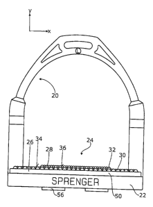
A complete stirrup can be seen from the FIGS. 1 and 2; the FIGS. 3 through 7
illustrate different component parts of the stirrup. It has a U-shaped piece
20, a
step plate 22 connected to said piece 20 and a stirrup insert 24 of the
invention
detachably connected to said step plate 22. The concrete implementations of
piece 20 and step plate 22 are discussed in the patent application under the
title
"Stirrup with Step Plate" of the same application date. The disclosure of said
patent is fully incorporated herein by reference. The S-shape of the piece 20
is
CA 02644714 2008-09-04
W02007/107440 4
PCT/EP2007/052016
visible, a left stirrup being shown. On the right stirrup, it extends in a Z
shape as
obtained in the mirror image of Fig. 1.
The stirrup system 24 has a frame-shaped external part 26 and an internal part
28 enclosed therein. The internal part 28 has an oval shape. In the
implementation as shown in the Figs. 1 through 7, which constitutes the first
exemplary embodiment, external part 26 and internal part 28 are permanently
joined together. They are made separately but form a unit in the finished,
assembled condition.
As can be seen from the Figs., the external part 26 has, inside the arms of
the
piece 20, a dimension that corresponds approximately to 1.2 times the
corresponding dimension of the internal part 28. The corresponding dimension
ratio can range between 1.1 and 3. Transverse thereto, meaning in the z
direction, the width dimension of the external part 26 is about 1.5 times the
corresponding width dimension of the internal part 28. Here, the ratio can
range
between 1.2 and 3.
The internal part 28 is configured to be softer than the external part, this
being
achieved by appropriate measures. The difference between the Shore hardness
of the softer internal part and the harder external part is at least ten
degrees of
Shore hardness, preferably more, for example 20 or 30. In the first exemplary
embodiment, the internal part is softer because the material from which it is
made is softer. Different rubber materials or elastomers are used for the two
parts 26, 28.
Both the surface 34 of the external part 26 and the surface 36 of the internal
part 28 are formed by dome-shaped studs 30, 32. The studs 30 of the external
part 26 are not as high as the studs 32 of the internal part 28; the
difference is
at least 1 mm. In the concrete exemplary embodiment, the height of the studs
30 of the external part 26 is only 55 A3 of the height of the studs 32 of the
internal part 28. The different height of the studs also makes the internal
part 28
softer than the external part 26. The difference in height can range between 1
and 7 mm.
CA 02644714 2008-09-04
WO 2007/107440 5
PCT/EP2007/052016
The surfaces of the external part 26 and the surface of the internal part 28
are
level, they extend parallel to the x-z plane. Together, they form the surface
of
the stirrup insert 24. In the exemplary embodiment, the surface 34 of the
external part 26 is located approximately 2 mm underneath the surface 36 of
the
internal part 28.
It is preferred that the external part 26 be configured in the form of a frame
with
a window that completely surrounds the internal part 28. The stirrup insert 24
has upper edges 38 which extend parallel to the x direction. It is
particularly
preferred that the external part 26 forms these bounding edges 38. The
internal
part 28 is intended to be spaced a distance of at least 5 mm apart from these
edges 38 on either side in the z direction. As a result, the harder outer part
26
forms the area about the edges 38, so that the rider has a firmer and tighter
feeling. As a result, the internal part 28 is substantially responsible for
adherence
whereas the external part 26 also serves for guiding. It is possible that the
internal part 28 extends as far as the arms of the piece 20, and possibly even
beyond, so that the internal part 28 can extend over the entire length of the
stirrup insert 24 in the x direction.
Preferably, the stirrup insert 24 is implemented such that, if the sole of a
boot is
loaded normally, the internal part 28 is pressed farther inward than the
external
part 26. In the used condition, both surfaces 34, 36 then substantially lie in
one
plane that is parallel to the x-z plane.
The stirrup insert has a bearing surface 50. It is located above the step
plate 22.
In the first exemplary embodiment, it is formed by the internal part 28 and by
a
portion of the external part 26. The stirrup insert 24 further has a holding
area
52. It is connected integral with the external part 26 and formed in
accordance
with prior art. It has an intermediate piece 54 that locates in at least one
recess
of the step plate 22 and holding arms 56 that project from underneath the step
plate 22 and engage laterally underneath said step plate. Corresponding
constructions are known in prior art and need not be discussed in closer
detail
herein.
CA 02644714 2008-09-04
WO 2007/107440 6
PCT/EP2007/052016
In the first exemplary embodiment, the holding area 52 is formed by the
external part 26 only. It is possible to also assign holding functions to the
internal part 28, meaning to form part of the holding area there. It is
preferred
that at least one portion of the holding area 52 be provided on the external
part
26, preferably integral therewith.
Fig. 8 shows an implementation wherein a shoulder 58 is added to a lower
surface of the internal part 28 shown. This shoulder has functions like the
holding area 52. In the concrete exemplary embodiment however, it does not
directly abut the step plate 22 but corresponding walls of the external part
26,
concretely an inner wall of the external part 26. The internal part 28
according to
the implementation shown in Fig. 8 is not solidly connected to the associated
external part 26. The external part 26 shown in the Figs. 3 through 5 can be
used. It is possible to make different implementations of the internal part 28
shown in Fig. 8, for example with differing stud formation, different
surfaces,
different material hardness, and so on, this also applying for the following
exemplary embodiments. The discrete internal parts 28 can then be exchanged.
The external part 26 must not be removed from the stirrup; it can remain on
the
step plate 22.
The third exemplary embodiment shown in Fig. 9 shows another alternative of an
exchangeable internal part 28. Here, in addition thereto, the surface 36 is
smooth. It is curved. It can be seen that the highest raised portion is
located in
the geometrical center of the surface 36 of the internal part 28. The highest
raised portion is located above the center of the step plate 22.
The internal part 28 is preferably placed in the center of the external part
.26;
this is shown in all the exemplary embodiments.
In the implementation shown in Fig. 9, there is an air chamber 60 or a free
space
underneath the layer 62 forming the surface 36. Here, the internal part 28 is
spaced from the surface of the step plate 22. When loaded, this air chamber 60
is reduced or at need used completely. In the implementation shown in Fig. 9,
the internal part 28 is made from two layers; it has the upper, more resilient
thinner layer 62 and a lower layer that is formed by the air chamber 60.
CA 02644714 2008-09-04
WO 2007/107440 7
PCT/EP2007/052016
In the implementation of the internal part 28 shown in Fig. 10, the surface 36
is
again level. It is formed by studs 32. Underneath the layer 62 there is now a
layer 64 made from a very soft material such as foam rubber. It has the same
function as the air chamber 60 in the exemplary embodiment shown in Fig. 9.