Note: Descriptions are shown in the official language in which they were submitted.
CA 02644866 2008-09-03
WO 2008/020895 PCT/US2007/005467
1
APPARATUS FOR DEACTIVATING
INSTRUMENTS AND DEVICES
Field of the Invention
[0001] The present invention relates to disinfection or deactivation of
medical,
dental, pharmaceutical, veterinary or mortuary instruments and devices, and
more
particularly, to a method and apparatus for deactivating items and for
maintaining such
items in a deactivated state.
Background of the Invention
[0002] Medical, dental, pharmaceutical, veterinary or mortuary instruments
and devices are routinely exposed to blood or other body fluids during medical
procedures. Following such procedures, a thorough cleaning and anti-microbial
deactivation of the instruments is required before subsequent use. Liquid
microbial
deactivation systems are now widely used to clean and deactivate instruments
and
devices that cannot withstand the high temperature of a steam deactivation
system.
Liquid microbial deactivation systems typically operate by exposing the
medical
devices and/or instruments to a liquid disinfectant or a deactivation
composition, such
as peracetic acid or some other strong oxidant. In such systems, the
instruments or
devices to be cleaned are typically placed within a deactivation chamber
within the
deactivation system, or in a container that is placed within the deactivation
chamber.
During a deactivation cycle, a liquid disinfectant is then circulated through
the
deactivation chamber (and the container therein).
[0003] The present invention provides a method and apparatus for microbially
deactivating medical instruments and devices.
Summary of the Invention
[0004] In accordance with the present invention, there is provided an
apparatus
for deactivating medical instruments and devices, comprised of a
decontamination
chamber. A circulation system is fluidly connected to the decontamination
chamber
and to a source for a microbial deactivation fluid. The circulation system has
a first
circulation flow path and second circulation flow path. A high-flow, low-
pressure
pump is disposed in the first circulation flow path. The high-flow, low-
pressure pump
is operable to pump fluid at a flow rate greater than about 7 gallons per
minute at a
fluid pressure of less than about 14 psig. A filter membrane is disposed in
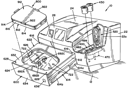
the second
CA 02644866 2008-09-03
WO 2008/020895 PCT/US2007/005467
2
circulation flow path. A low-flow, high-pressure pump is disposed in the
second
circulation flow path. The low-flow, high-pressure pump is operable to pump
fluid at
a flow rate less than about 6 gallons per minute at a pressure greater than
about 20 psig
of fluid pressure.
100051 In accordance with another aspect of the present invention, there is
provided an apparatus for deactivating medical instruments and devices
comprised of
a decontamination chamber. A circulation system fluidly connects to the
decontamination chamber and to a source for a microbial deactivation fluid.
The
circulation system is comprised of a first circulation flow path communicating
with
the decontamination chamber wherein between about 65% and about 80% of the
fluid
in the circulation system flows in the first circulation flow path. A second
circulation
flow path is connect to the first circulation flow path, wherein between about
20% and
about 35% of the fluid in the circulation system flows in the second
circulation flow
path. A first pump conveys fluid in the first circulation flow path. A second
pump
conveys fluid in the second circulation flow path. A filter element is
disposed in the
second circulation flow path.
[0006] In accordance with yet another aspect of the present invention, there
is
provided an apparatus for deactivating medical instruments and devices,
comprised of
a decontamination chamber dimensioned to receive medical instruments and
devices
to be microbially deactivated. A chemistry delivery assembly is provided to
generate
a deactivation fluid from dry chemistry and water. A water inlet line
introduces water
into the apparatus. The water inlet line is connected to the chemistry
delivery system.
A circulation system circulates a deactivating fluid through the deactivation
chamber.
The circulation system has a first fluid path and a second fluid path. A
filter is
disposed within the second fluid path for filtering fluid within the
apparatus. A first
pump is disposed in the first fluid path to deliver fluid directly along the
first fluid
path to the deactivation chamber. The first pump is operable to pump fluid at
a flow
rate greater than about 7 gallons per minute at a fluid pressure of less than
about 14
psig. A second pump is disposed in the second fluid path to deliver fluid
through the
filter. The second pump is operable to pump fluid at a flow rate of less than
about 6
gallons per minute at a fluid pressure of greater than about 20 psig.
CA 02644866 2008-09-03
WO 2008/020895 PCT/US2007/005467
3
[0007] In accordance with still another aspect of the present invention, there
is
provided an apparatus for deactivating medical instruments and devices,
comprised of
a decontamination chamber dimensioned to receive medical instruments and
devices
to be microbially deactivated. A circulation system is provided to circulate a
deactivating fluid through the deactivation chamber. The circulation system
has a first
fluid path that is connected to the decontamination chamber and a second fluid
path
that is connected to the first fluid path. A water inlet line introduces water
into the
apparatus. The water inlet line is connected to the second fluid path. A
filter is
disposed within the second fluid path to filter fluid within the apparatus. A
first pump
is disposed in the first fluid path to circulate fluid in the first fluid
path. A second
pump is disposed in the second fluid path to circulate fluid in the second
fluid path.
[0008] One advantage of the present invention is an apparatus for deactivating
medical instruments and items.
[0009] Another advantage of the present invention is a container for holding
medical instruments and items during a microbial deactivation process, which
container maintains the instruments in a deactivated environment therein for a
prolonged period of time after removal of the container from the apparatus.
[0010] A still further advantage of the present invention is a container as
described above that may be used as a storage device for storing the
microbially
deactivated instruments.
[0011] Another advantage of the present invention is a compact, front-loading
apparatus for deactivating medical instruments and items.
100121 A still further advantage of the present invention is an apparatus as
described above having a drawer system that opens at a downward angle to a
user.
[0013] Another advantage of the present invention is an apparatus for
deactivating medical instruments and items having a circulation system that
allows for
separate rinsing of a chemistry container that is used to generate a microbial
deactivation fluid.
[0014] A still further advantage of the present invention is an apparatus for
deactivating medical instruments and items having a chemistry container that
can be
easily modified to accommodate different chemistries.
CA 02644866 2008-09-03
WO 2008/020895 PCT/US2007/005467
4
100151 A still further advantage of the present invention is an apparatus for
deactivating medical instruments and items that utilizes an instrument
container that
can be configured to include different instruments and devices.
[0016] Another advantage of the present invention is an apparatus for
deactivating medical instruments and items that circulates a deactivation
fluid through
sterile water filters to prevent the growth of microorganisms on filter
membrane.
[0017] Another advantage of the present invention is an apparatus for
deactivating medical instruments and items that utilizes a two-part dry
chemistry.
[0018] A still further advantage of the present invention is an apparatus for
deactivating medical instruments and items that utilizes a chemistry container
that has
a connector-less design.
100191 A still further advantage of the present invention is an apparatus for
deactivating medical instruments and items having a high-pressure zone and a
low-
pressure zone to induce constant flow of deactivation fluid through the
apparatus.
[0020] These and other advantages will become apparent from the following
description of a preferred embodiment taken together with the accompanying
drawings and the appended claims.
Brief Description of the Drawings
[0021] The invention may take physical form in certain parts and arrangement
of parts, a preferred embodiment of which will be described in detail in the
specification and illustrated in the accompanying drawings which form a part
hereof,
and wherein:
[0022] FIG. 1 is a perspective view of an automated reprocessor for
microbially deactivating medical instruments, according to the present
invention;
[0023] FIG. 2 is a perspective view of the reprocessor of FIG. 1, showing a
movable drawer in an opened position and an instrument container removed
therefrom, and also showing an access panel to a chemistry delivery system in
an
opened position and a chemistry container remover therefrom;
[0024] FIG. 3 is a side, elevational view of the reprocessor of FIG. 1,
showing
the reprocessor on a counter top relative to a user;
[0025] FIG. 4 is a schematic diagram of the reprocessor shown in FIG. 1;
CA 02644866 2008-09-03
WO 2008/020895 PCT/US2007/005467
[0026] FIG. 5 is a schematic diagram of the reprocessor, illustrating the path
of
fluids through the reprocessor during a reprocessor fill phase;
[0027] FIG. 6 is a schematic diagram of the reprocessor, illustrating the path
of
fluids through the reprocessor during a system circulate phase;
[0028] FIG. 7 is a schematic diagram of the reprocessor, illustrating the path
of
fluids through the reprocessor during a chemistry generation phase;
[0029] FIG. 8 is a schematic diagram of the reprocessor, illustrating the path
of
fluids through the reprocessor during an instrument exposure phase;
100301 FIG. 9A is a schematic diagram of the reprocessor, illustrating the
path
of fluids through the reprocessor during a first part of a drain phase;
[0031] FIG. 9B is a schematic diagram of the reprocessor, illustrating the
path
of fluids through the reprocessor during a second part of the drain phase;
[0032] FIG. 10 is a sectional view of a filter element from the reprocessor
shown in FIG. 1;
[0033] FIG. 11 is a sealed package containing a chemistry-holding device that
is used in the reprocessor shown in FIG. 1;
[0034] FIG. 12 is a sectional view taken along lines 12-12 of FIG. 11;
100351 FIG. 13 is a sectional view of a chemistry-delivery system used in the
reprocessor shown in FIG. 1, showing the chemistry-delivery system in an open
position;
[0036] FIG. 14 is a sectional view taken along lines 14-14 of FIG. 13;
[0037] FIG. 15 is a sectional view taken along lines 15-15 of FIG. 13;
[0038] FIG. 16 is a partially sectioned, side-elevational view of the
chemistry-
delivery system, showing a chemistry-holding device disposed therein;
[0039] FIG. 17 is a sectional view of the chemistry-delivery system in
operation;
[0040] FIG. 18 is a cross-sectional view of a drawer assembly from the
apparatus show in FIG. 1;
[0041] FIG. 19 is an enlarged view, showing a connector assembly for the
drawer assembly show in FIG. 18;
[0042] FIG. 20 is a sectional view taken along lines 20-20 of FIG. 19;
CA 02644866 2008-09-03
WO 2008/020895 PCT/US2007/005467
6
[0043] FIG. 21 is a sectional view taken along lines 21-21 of FIG. 19;
[0044] FIG. 22 is a sectional view taken along lines 22-22 of FIG. 19;
[0045] FIG. 23 is a partially sectioned view of the connector assembly shown
in FIG. 19;
[0046] FIG. 24 is a top plan view of an instrument storage container used in
the apparatus shown in FIG. 1;
[0047] FIG. 25 is a sectional view taken along lines 25-25 of FIG. 24, showing
a valve assembly in an opened position;
[0048] FIG. 26 is a sectional view of the valve assembly shown in FIG. 25,
showing the valve assembly in a closed position;
[0049] FIG. 27 is a sectional view taken along lines 27-27 of FIG. 24, showing
a seal arrangement on the instrument storage container;
[0050] FIG. 28 is a perspective view of a storage cabinet for storing
decontaminated instrument containers, illustrating another aspect of the
present
invention;
[0051] FIG. 29A is a sectional view of an alternate embodiment of a valve
assembly, showing the valve assembly in a first position;
[0052] FIG. 29B is a partially sectioned view of the valve assembly of FIG.
29A, showing the valve assembly in a second position;
[0053] FIG. 29C is partially section view taken along lines 29C-29C of FIG.
29B, showing a filter element; and
[0054] FIG. 29D is a perspective view of the filter element.
Detailed Description of Preferred Embodiment
[0055] Referring now to the drawings wherein the showings are for the
purpose of illustrating a preferred embodiment of the invention only, and not
for the
purpose of limiting same, FIG. 1 shows an apparatus 10 for microbially
deactivating
medical instruments and other devices, illustrating a preferred embodiment of
the
present invention. Apparatus 10 is designed to rest upon a table or countertop
12, as
illustrated in FIG. 1. Countertop 12 in and of itself forms no part of the
present
invention. Apparatus 10 includes a housing structure 22 containing the
operative
components of apparatus 10. Housing structure 22 has an upper surface 24 that
slopes
CA 02644866 2008-09-03
WO 2008/020895 PCT/US2007/005467
7
generally downward toward a front face 26. Front face 26 has an upper section
26a
and a lower section 26b. Upper section 26a includes a display panel 28.
Display
pane128 is connected to a controller system (not shown) that controls the
operation of
apparatus 10.
[0056] A drawer assembly 600 has a front face panel 634 that is coplanar with
lower section 26b of front face 26 when drawer assembly 600 is in a closed
position,
as illustrated in FIG. 1. A drawer actuation button 636 is provided on front
panel 634
of drawer assembly 600. Drawer assembly 600 is movable from a closed position,
as
shown in FIG. 1, to an opened position, as illustrated in FIG. 2. Drawer
assembly 600
includes a drawer tray 622 having a flat upper surface 632. A recess or cavity
624 is
formed in tray 622, as illustrated in FIG. 2. Surface 632 extends around the
periphery
of recess or cavity 624. Cavity 624 is dimensioned to receive an instrument
container
.800. Container 800 is provided to receive the instruments or devices to be
deactivated. Container 800 is dimensioned to be received within cavity 624, as
illustrated in FIG. 2.
[0057] A small, rectangular access panel 22a is formed in housing structure
22.
In the embodiment shown, access panel 22a is formed to the right side of
display panel
28 in a recess formed in housing structure 22. Access pane122a is movable
between a
closed position, shown in FIG. 1, and an opened position, shown in FIG. 2. In
its
opened position, access panel 22a allows access to a chemistry-delivery system
400
that shall be described in greater detail below. Chemistry-delivery system 400
is
dimensioned to receive a chemistry-holding device 430 that contains dry
chemicals
that, when combined with water, form a microbial deactivation fluid used in
apparatus
10. As best illustrated in FIG. 3, drawer assembly 600 opens in a generally
downward
direction. In other words, drawer assembly 600 slides into and out of housing
structure 22 in a plane that is sloping downwardly relative to the housing
structure 22.
[0058] Referring now to FIG. 4, a simplified, schematic piping diagram of
apparatus 10 is shown. As schematically illustrated in FIG. 3, drawer assembly
600
includes a drive assembly 650, including a rack 658 and a pinion gear 656.
Rack 658
is connected to drawer assembly 600 and is movable by pinion gear 656 that is
driven
by a motor 652. In FIG. 4, instrument container 800 is shown disposed within
cavity
CA 02644866 2008-09-03
WO 2008/020895 PCT/US2007/005467
8
624 defined by drawer tray 622. When drawer assembly 600 is in the closed
position,
as shown in FIG. 4, drawer tray 622 is disposed beneath a plate 642. A static
seal
element 644 is disposed on the bottom side of plate 642 for contact with the
planar
portion of drawer tray 622. In this respect, static seal 644 is generally
continuous
about the periphery of cavity 624 in drawer tray 622. An air-inflatable
bladder 646 is
provided on the top side of plate 642 to force plate 642 and static seal 644
into sealing
engagement with the planar portion of drawer tray 622. Inflatable bladder 646
is
disposed between the upper surface of plate 642 and housing structure 22 to
force
plate 642 into sealing engagement with drawer tray 622. A plurality of springs
647
(best shown in FIG. 18) are connected at one end to the upper side of plate
642 and at
the other end to housing structure 22. Springs 647 are tension springs that
bias plate
642 and static sea1644 away from the planar portion of drawer tray 622.
[0059] As schematically illustrated in FIG. 4, when instrument container 800
is disposed within the recess 624 in drawer tray 622, instrument container 800
is
connected to fluid inlet lines and a drain line of a fluid circulation system
100.
Instrument container 800 is also in communication with an air conduit 826 for
inflating a seal 824 disposed between a tray 812 and a lid 912 of instrument
container
800, as shall be described in greater detail below. When drawer assembly 600
is in a
closed position and inflatable bladder 646 is activated to force static seal
644 into
contact with the planar portion of drawer tray 622, a decontamination chamber
is
formed within apparatus 10, as schematically illustrated in FIG. 4. Fluid
circulation
system 100 provides microbial deactivation fluid to the deactivation chamber
and is
further operable to circulate the microbial deactivation fluid through the
decontamination chamber, through instrument container 800 and through
instruments
contained within instrument container 800.
[0060] To enable drawer assembly 600 and drawer tray 622 to move into and
out of housing structure 22 of apparatus 10, the input lines and the drain
lines from
fluid circulation system 100 are attachable and detachable from drawer tray
622 by
means of a connector assembly 660 that shall be described in greater detail
below.
[0061] Fluid circulation system 100 includes a water inlet line 102 that is
connected to a source of heated water (not shown). A valve 104 is disposed
within
CA 02644866 2008-09-03
WO 2008/020895 PCT/US2007/005467
9
water inlet line 102 to control the flow of water into apparatus 10. A pair of
macro
filters 106, 108 are provided in water inlet line 102 downstream from valve
104 to
filter large contaminants that may exist in the incoming water. A flow
restrictor 112 is
disposed in water inlet line 102 to regulate the flow of water therethrough.
An
ultraviolet (UV) treatment device 114 for deactivating organisms within the
water
source is preferably provided in water inlet line 102. A water valve 116
controls the
flow of water from water inlet line 102 to a system feeder line 122. System
feeder line
122 includes a filter element 300 to filter microscopic organisms from the
incoming
water source to provide sterile water to fluid circulation system 100.
[0062] System feeder line 122 splits into a first branch feeder line 124 and a
second branch feeder line 126 downstream of filter element 300. First branch
feeder
line 124 extends from system feeder line 122, as schematically illustrated in
FIG. 4. A
heater element 132 is disposed within first branch feeder line 124. A first
temperature
sensor 134 is disposed within first branch feeder line 124 upstream of heater
element
132. First temperature sensor 134 is operable to provide signals to the system
controller indicative of the temperature of the water upstream of heater
element 132.
A second temperature sensor 136 is attached to first branch feeder line 124
downstream of heater element 132 to provide temperature measurements of water
downstream of heater element 132. Second temperature sensor 136 is operable to
provide signals to the system controller indicative of the temperature of the
water
downstream of heater element 132. A sterilant sensor 142 is disposed within
first
branch feeder line 124. Sterilant sensor 142 is operable to provide signals to
the
system controller indicative of the concentration of a sterilant flowing
within first
branch feeder line 124. A conductivity probe 144 is attached to first branch
feeder
line 124 downstream of sterilant sensor 142. Conductivity probe 144 is
operable to
provide signals to the system controller indicative of the conductivity of the
water in
first branch feeder line 124. First branch feeder line 124 includes a branch
section
124a that extends through the plate in the drawer assembly to communicate with
the
recess or cavity defined by the drawer tray. A drain line 146 is also
connected to first
branch feeder line 124 upstream of sterilant sensor 142. A valve 147 is
disposed
within drain line 146 to control the flow of fluid through drain line 146.
CA 02644866 2008-09-03
WO 2008/020895 PCT/US2007/005467
[0063] Second branch feeder line 126 also connects to the connector assembly
660. A pressure sensor 148 is disposed within second branch feeder line 126.
Pressure sensor 148 is capable of measuring the pressure of the fluid in
second branch
feeder line 126 and providing a signal that is proportional to the measured
pressure to
the system controller. An air line 152 is connected to second branch feeder
line 126,
as illustrated in FIG. 4. Air line 152 is connected to a source (not shown) of
dry air.
A filter 154 is disposed within air line 152. A directional valve 156 is
disposed within
air line 152. Directional valve 156 is arranged to allow air to be forced into
second
branch feeder line 126, but to prevent water or fluids within second branch
feeder line
126 from flowing toward the source of air. A valve 158 is disposed within
second
branch feeder line 126, between pressure sensor 148 and where air line 152
connects
to second branch feeder line 126.
[0064] A return line 162 is connected at one end to the connector assembly
660. The other end of return line 162 has a first branch 162a that connects to
the inlet
side of a pump 172. Pump 172 is preferably a high pressure, low volume pump,
as
shall be described in greater detail below. Pump 172 preferably is a positive
displacement pump that is capable of pumping between about 2 gallons per
minute
and about 6 gallons per minute. In one embodiment, pump 172 is capable of
pumping
between about 4 gallons per minute and about 5 gallons per minute. In another
embodiment pump 172 is capable of pumping about 3.5 gallons per minute. Pump
172 is capable of pumping between about 20 psig and about 60 psig of fluid
pressure.
In one embodiment, pump 172 is capable of pumping between about 30 psig and
about
50 psig of fluid pressure. In another embodiment, pump 172 is capable of
pumping
about 40 psig of fluid pressure. The outlet side of pump 172 defines the
beginning of
system feeder line 122. A valve 164 is disposed within system feeder line 122
between pump 172 and the location where water inlet line 102 joins to system
feeder
line 122. A drain line 166 is connected to return line 162. A valve 168 is
disposed
within drain line 166 to control the flow of fluid therethrough.
[0065] Return line 162 includes a second branch 162b that connects to the
inlet
side of a pump 182. Pump 182 is a high volume pump. Pump 182 preferably is a
centrifugal pump that is capable of pumping between about 7 gallons per minute
and
CA 02644866 2008-09-03
WO 2008/020895 PCT/US2007/005467
11
about 15 gallons per minute at between about 5 psig and about 14 psig of fluid
pressure. In one embodiment, pump 182 pumps between about 8 gallons per minute
and about 12 gallons per minute at between about 7 psig and about 12 psig of
fluid
pressure. In another embodiment, pump 182 pumps about 10 gallons per minute at
about 9 psig of fluid pressure.
[00661 Pump 172 pumps between about 10% and about 46% of the total fluid
flow in the system and pump 182 pumps between about 54% and about 90% of the
total fluid flow in the system. In one embodiment, pump 172 pumps between
about
20% and about 35% of the total fluid flow in the system and pump 182 pumps
between about 65% and about 80% of the total fluid flow in the system. In
another
embodiment, pump 172 pumps about 25% of the total fluid flow in the system and
pump 182 pumps about 75% of the total fluid flow in the system. The outlet
side of
pump 182 is connected to an auxiliary system feeder line 184 that is connected
to first
branch feeder line 124. A pressure sensor 186 is disposed within auxiliary
system
feeder line 184 at a location preceding the juncture where auxiliary system
feeder line
184 connects with first branch feeder line 124. Pressure sensor 186 is capable
of
measuring the pressure of the fluid in auxiliary system feeder line 184 and
providing a
signal that is proportional to the measured pressure to the system controller.
A valve
125 is disposed in first branch feeder line 124 to control fluid flow in
branch feeder
line 124. Valve 125 is disposed at a location upstream of the juncture where
auxiliary
system feeder line 184 connects with first branch feeder line 125. When valve
125 is
in a first position, between about 75% and about 100% of the flow in branch
feeder
line 124 is cable of flowing into auxiliary feeder line 184. In one
embodiment,
between about 90% to about 100% of the flow in branch feeder line 124 is cable
of
flowing into auxiliary feeder line 184. In another embodiment, about 100% of
the
flow in branch feeder line 124 is cable of flowing into auxiliary feeder line
184. When
valve 125 is in a second position between about 5% to about 25% of the flow in
branch feeder line 124 is cable of flowing into auxiliary feeder line 184. In
one
embodiment, between about 5% and about 10 % of the flow in branch feeder line
124
is cable of flowing into auxiliary feeder line 184. In another embodiment,
about 5% of
the flow in branch feeder line 124 is cable of flowing into auxiliary feeder
line 184.
CA 02644866 2008-09-03
WO 2008/020895 PCT/US2007/005467
12
[0067] A filter bypass line 192 communicates with system feeder line 122 on
opposite sides of filter element 300. Specifically, one end of bypass line 192
is
connected to system feeder line 122 between pump 172 and valve 164. The other
end
of bypass line 192 communicates with system feeder line 122 downstream of
filter
element 300, but before the juncture where system feeder line 122 splits into
first
branch feeder line 124 and second branch feeder line 126. As shown in FIG. 4,
a
valve 194 is disposed between filter element 300 and downstream of the
connection of
bypass line 192 to system feeder line 122. A drain line 196 is connected to
system
feeder line 122 between valve 194 and filter element 300. A valve 198 is
disposed
within drain line 196 to regulate flow therethrough. A drain line 328 is also
connected
to filter element 300. A valve 327 is disposed within drain line 328 to
control the flow
of fluid therethrough. A temperature sensor 332 is connected to filter element
300.
Temperature sensor 332 is capable of measuring the temperature of the fluid in
filter
element 300 and providing a signal that is proportional to the measured
temperature to
the system controller. A pressure sensor 334 is also connected to filter
element 300.
Pressure sensor 334 is capable of measuring the pressure of the fluid in
filter element
300 and providing a signal that is proportional to the measured pressure to
the system
controller.
[0068] A test line 212 is connected to filter element 300 to conduct integrity
tests of filter element 300. As illustrated in FIG. 4, one end of test line
212 is
connected to filter element 300 and the other end is connected to a drain. Two
spaced-
apart valves 214, 216 are disposed in test line 212. Between valves 214 and
216, a
first test line section 212a is defined. Between valve 216 and filter element
300, a
second test line section 212b is defined. An air line 222 from a source of
pressurized,
filtered, clean air is connected to test line 212. Air line 222 is connected
to test line
section 212a between valves 214, 216. A check valve 224 is disposed in air
line 222.
Check valve 224 is arranged to allow one-way flow of air to test line section
212a. A
pressure sensor 226 is disposed in test line section 212a between valves 214,
216 to
measure the air pressure in test line section 212a and provide a signal that
is
proportional to the measured air pressure in test line to the system
controller. First test
line section 212a includes a T-fitting 232 for connecting first test line
section 212a to
CA 02644866 2008-09-03
WO 2008/020895 PCT/US2007/005467
13
one side of a differential pressure sensor 234. A valve 236 is disposed in T-
fitting 232
to control connection of first test line section 212a to differential pressure
sensor 234.
A second T-fitting 242 is disposed in second test line section 212b and is
connected to
a second side of differential pressure sensor 234. Differential pressure
sensor 234 is
cable of the measuring the difference in the pressure of the fluid on one side
of
differential pressure sensor 234 and pressure on the second side of
differential
pressure sensor 234. Differential pressure sensor is then capable of providing
a signal
that is proportional to the measured difference in pressure to the system
controller. A
valve 246 is disposed in second T-fitting 242 to control connection of second
test line
section 212b to differential pressure sensor 234.
[0069] A chemistry inlet line 252 is fluidly connected to first branch feeder
line 124. A valve 254 is disposed in chemistry feed line 252 to control flow
of fluid
therethrough. A pressure sensor 256 is disposed within chemistry inlet line
252 for
providing signals to the system controller indicative of the pressure of
fluids therein.
Chemistry inlet line 252 splits into two sections 252a, 252b that both connect
to a
chemistry-delivery system 400. Chemistry-delivery system 400, that will be
described
in greater detail below, is comprised of a chemistry housing 470 and a movable
lid
520 that attaches to chemistry housing 470. Chemistry housing 470 of chemistry-
delivery system 400 includes two separate compartments or receptacles 482,
484.
Compartment 482 is dimensioned to receive a container containing a chemical
reagent. Compartment 484 is dimensioned to receive a container that contains
builder
material to react with the chemical reagent in the first container to create a
microbial
deactivation fluid. As shall be described in greater detail below, lid 520 is
designed to
isolate the respective compartments when in a closed position.
[0070] Section 252b of chemistry inlet line 252 communicates with the
container containing the builder material. Section 252a of chemistry inlet
line 252
connects to the container holding the chemical reagent. A valve 258 is
disposed
within section 252a of chemistry inlet line 252 to control the flow of fluid
therethrough. ,
[0071] Each compartment of chemistry housing 470 of chemistry-delivery
system 400 is designed to have an outlet port formed at the upper edge
thereof. A
CA 02644866 2008-09-03
WO 2008/020895 PCT/US2007/005467
14
chemistry outlet line 262 connects chemistry-delivery system 400 to return
line 162.
Chemistry outlet line 262 has a first overflow line 262a and a second overflow
line
262b. First overflow line 262a connects the upper portion of the first
compartment of
the housing to outlet line 262. Second overflow line 262b connects the upper
portion
of the second compartment of the housing to outlet line 262. A chemistry
housing
drain line 264 connects the bottom of chemistry housing 470 to chemistry
outlet line
262. Chemistry housing drain line 264 has a first section 264a connected to
the lowest
part of the first compartment in chemistry housing 470, and a second section
264b is
connected to the lowest part of the second compartment in chemistry housing
470. A
valve 266 disposed within chemistry housing drain line 264 controls the flow
of fluid
from chemistry-delivery system 400. A drain line 272 connects to chemistry
outlet
line 262. A valve 274 is disposed in drain line 272 to control the flow of
fluid
therethrough. Downstream of drain line 272, a valve 276 is disposed in
chemistry
outlet line 262.
[0072] As shown in FIG. 4, a portion 252a of chemistry inlet line 252 is
connected to chemistry outlet line 262. In this respect, portion 252a of
chemistry inlet
line 252 is disposed relative to two valves 254, 276 such that chemistry inlet
line 252
is always in communication with chemistry outlet line 262 and ultimately, in
connection with return line 162. In other words, a direct path is established
between
first branch feeder line 124 and chemistry outlet line 262. A connecting line
282
connects water inlet line 102 to chemistry inlet line 252. Two spaced-apart
valves
284, 286 are disposed in connecting line 282. An air line 288 is connected to
connecting line 282 between valves 284, 286. A direction check valve 289 is
disposed
in air line 288 to permit air flow only into connecting line 282.
[0073] Referring now to the drawer assembly shown in FIG. 4, an overflow
line 292 is connected to plate 642 so as to communicate with the
decontamination
chamber. The other end of overflow line 292 is connected to a drain source. A
check
valve 293 is disposed within overflow line 292 to allow the flow of fluid out
of the
decontamination chamber, but to restrict the flow of any fluid into the
decontamination chamber through overflow line 292. A sensor 294 is disposed
within
overflow line 292 downstream from directional check valve 293 to indicate when
fluid
CA 02644866 2008-09-03
WO 2008/020895 PCT/US2007/005467
is flowing therethrough. A make-up air line 296 is also connected to the
decontamination chamber, as schematically illustrated in FIG. 3. A filter
element 297
is disposed within make-up air line 296 to filter any air flowing into the
decontamination chamber. In this respect, a directional check valve 298 is
disposed
within make-up air line 296 between filter element 297 and the decontamination
chamber. Directional check valve 298 allows the flow of air into the
decontamination
chamber, but restricts the flow of air or fluid out of the decontamination
chamber.
[0074] FILTER ASSEMBLY 300
[0075] Referring now to FIG. 10, the filter assembly 300 is best seen. Filter
assembly 300 is comprised of a support member 310 having a filter cartridge
340
attached thereto. Support member 310 has a central bore 312 formed therein. An
annular slot 314 is formed in support member 310 around bore 316. Annular slot
314
is concentric to central bore 312 and defines an annular wall 316 within
support
member 310. A first passage 322 communicates with slot 314. A second passage
324
communicates with bore 312. Support member 310 is designed to be inserted into
system feeder line 122 by conventional fasteners, such that first passage 322
defines
an inlet port and second passage 324 defines an outlet port. A drain opening
326
extends from the bottom of support member 310 to annular slot 314. A drain
conduit
328 is attached to drain opening 326.
[0076] Filter cartridge 340 includes a housing 342 and a base 344 that are
dimensioned to contain an inner filter element 370. Base 344 is comprised of a
mounting plate 346 having two annular walls 352, 354 that extend downward from
the
bottom of plate 346. The inner annular wall 352 is dimensioned to be received
within
bore 312, formed in support member 310. Outer annular wall 354 is dimensioned
to
engage the outer-most inner surface of annular slot 314. 0-rings 356 are
provided on
outer surfaces of inner and outer walls 352, 354 to form a seal with surfaces
of central
bore 312 and annular slot 314, as illustrated in FIG. 10. An upper annular
wall 362
extends from the upper surface of plate 346. The free end of wall 362 includes
an
outward-extending flange 364 that defines a planar upper surface 366. A
central bore
368 extends through base 344, as illustrated in FIG. 10. Housing 342 is
preferably
attached to base 344 by means of ultrasonic welding.
CA 02644866 2008-09-03
WO 2008/020895 PCT/US2007/005467
16
[00771 A filter element 370 is mounted onto surface 366 of filter base 344. In
the embodiment shown, filter element 370 has three layers 372a, 372b, 372c of
filter
media. As will be appreciated by those skilled in the art, each layer 372a,
372b, 372c
filters a different size particle, with inner layer 372a having the highest
filtering
capability. A cap 374 is provided at the upper end of filter element 370. An
outer
annular chamber 376 is formed between the outer housing 342 and outer layer
372c of
the filter media. A central cavity 378 is formed within filter element 370.
Cavity 378
communicates with bore 312 in support member 310, which in turn communicates
with feeder feed line 122. Filter cartridge 340 may be attached to support
member 310
in a number of different ways. In the embodiment shown, a bayonet-type lock
arrangement is shown.
100781 Test line 212b is attached to housing 342, and it communicates with the
annular chamber 376 formed therein. Openings 348 are formed through plate 346
of
base 344 to permit the flow of fluid therethrough. Openings 348 are positioned
to
allow annular chamber 376 to communicate with slot 314, as shown in FIG. 10.
As
illustrated by arrows in FIG. 10, water or a decontamination fluid from system
feed
line 122 flows into first passage 322 (the inlet port) of support member 310
and
upwards through opening 348 in plate 346 into annular chamber 376. The water
or
decontamination fluid then flows through filter element 370, where the water
or fluid
is filtered as it passes through layers 372a, 372b, 372c of filter media. The
water or
fluid then flows down through cavity 378 and central bore 312 in support
member 310
and, ultimately, to second passage 324 (the outlet port) into fluid feed line
122.
[0079] CHEMISTRY-DELIVERY SYSTEM 400
[0080] Referring now to FIGS. 11-17, the chemistry-delivery system 400 is
best seen. Chemistry-delivery system 400 is designed to use a chemistry-
holding
device 430. FIG. 11 shows a chemistry-storage package 412 containing a
chemistry-
holding device 430. Chemistry-storage package 412 is comprised of a molded
base
414 having a peel-away lid or cover 416. Base 414 is generally comprised of an
integrally molded polymer material. Cover 416 is preferably a polymer film
that is
attached to base 414, so as to be easily peeled away. A tab 418 extends from,
and is
integrally formed as part of cover 416 to facilitate removal of cover 416 from
base
CA 02644866 2008-09-03
WO 2008/020895 PCT/US2007/005467
17
414. Chemistry-storage package 412 is dimensioned to loosely contain chemistry-
holding device 430.
[0081] Referring now to FIG. 12, chemistry-holding device 430 is best seen.
Chemistry-holding device 430 is basically comprised of two side-by-side
containers
432, 434 that are connected along their upper surfaces by a bridge portion
436. Both
containers 432, 434 are slightly conical in shape and include a tubular body
438 that is
defined by an annular wa11442. The lower end of each wa11442 includes an
inwardly
turned edge 444 that defines an opening 446 at the bottom of each container
432, 434.
The upper end of each container 432, 434 defines an opening 448. The upper end
of
container 432, 434 includes an outward extending, stepped flange 452. Stepped
flange
452 defines an annular, upward-facing surface 452a.
[0082] A filter element 456 is disposed at the bottom of each container 432,
434. Filter element 456 is essentially a flat disk that is dimensioned to have
an outer
peripheral shape, matching the inner profile of each container 432, 434. In
this
respect, each filter element 456 is dimensioned to be snugly received in the
bottom of
container 432, 434, with the outer edge of filter element 456 resting on
upward-facing
surface defined by inwardly extending edge 444.
[0083] A second filter element 458 is provided in container 432 to close the
opened upper end thereof. Like filter element 456, filter element 458 is a
flat disk that
is dimensioned to have an outer peripheral shape, matching the inner profile
of
stepped flange 452 of wall 442. In this respect, in the embodiment shown,
filter
element 458 is circular in shape and is dimensioned to be snugly received
within
stepped-flange 452 of container 432, with filter element 458 resting on
annular surface
452a defined by stepped flange 452.
100841 A thin polymer layer 462 is provided to close the opened upper end of
container 434. Polymer layer 462 is dimensioned to rest upon annular surface
452a
defined by stepped flange 452 of container 434. Filter elements 456, 458 and
polymer
layer 462 are preferably ultrasonically welded to containers 432, 434.
[0085] Filter elements 456, 458 are formed of a filter material that is
impermeable to the dry reagents to be contained within containers 432, 434,
but is
permeable to water and to dissolved reagents. Filter element 456 is preferably
CA 02644866 2008-09-03
WO 2008/020895 PCT/US2007/005467
18
dimensioned to filter particles larger than 50 microns ( m) and, more
preferably, to
filter particles of about 10 microns ( m). Suitable filter materials include
polypropylene, polyethylene, nylon, rayon, rigid porous media (such as
POREXTM),
expanded plastic or other porous plastic, fabric, felt, mesh, and analogous
materials.
The filtering capabilities of the selected filtering material are related to
the dry reagent
contained within respective container 432, 434. In a preferred embodiment,
filter
element 456 is preferably formed of an ethylene-based polymer, such as
polypropylene or polyethylene. Container 432 is dimensioned to contain a
predetermined amount of acetylsalicylic acid, i.e., aspirin.
[0086] Container 434 is dimensioned to receive builder components that
contain a pre-salt, preferably sodium perborate. The builder components are
supplied
at sufficient amounts to react with the acetylsalicylic acid to generate
peracetic acid at
a concentration of 1,500 ppm or better with the volume of water to be used in
the
system in which chemistry-delivery system 400 is to be used. The sodium
perborate
generates hydrogen peroxide, which, in combination with acetylsalicylic acid
as an
acetyl donor, forms peracetic acid.
[0087] The use of powdered reagents that react in a common solvent to
generate chlorine gas, hydrogen peroxide, hypochlorous acid, hypochlorides, or
other
strong oxidants which have biocidal effects is also contemplated.
[0088] Container 434 also preferably includes various chemistries, such as
buffers, inhibitors and wetting agents. Preferred copper and brass corrosion
inhibitors
include azoles, benzoates, and other five-member ring compounds,
benzotriazoles,
tolytriazoles, mercaptobenzothiazole, and the like. Other anti-corrosion
buffering
compounds include phosphates, molybdates, chromates, dichromates, tungstates,
vanadates, and other borates, and combinations thereof. These compounds are
effective for inhibiting steel and aluminum corrosion. For hard water in which
calcium and magnesium salts may tend to precipitate, a sequestering reagent,
such as
sodium hexametaphosphate, is also included.
[0089] As illustrated in FIG. 12, chemistry-storage package 412 is
dimensioned to receive the chemistry-holding device 430, so as to allow
storage and
shipping of the chemistry-holding device 430 in a sealed package.
CA 02644866 2008-09-03
WO 2008/020895 PCT/US2007/005467
19
[0090] Referring now to FIGS. 13-17, chemistry-delivery system 400 is best
seen. Chemistry-delivery system 400 is comprised of an elongated, oblong
housing
470 having a lid 520 that is pivotally attached thereto. An outward extending
collar
472 extends around the periphery of housing 470. As best seen in FIGS. 13, and
14,
an obround recess 474 is formed in the upper surface of housing 470. Housing
470
includes two spaced-apart, side-by-side compartments or receptacles 482, 484
that are
dimensioned to receive, respectively, containers 432, 434 of chemistry-holding
device
430. Compartments 482, 484 extend from recess 474 into housing 470.
Compartments 482, 484 are generally cylindrical in shape and slightly larger
than
containers 432, 434 to define a space 488 around the sides and bottoms of
containers
432, 434, as best illustrated in FIG. 17.
[0091] Stepped regions 486, 488 are formed at the upper ends of
compartments 482, 484. Stepped regions 486, 488 are dimensioned to receive
stepped
flanges 452 on containers 432, 434 and are formed below the surface of recess
474, as
best seen in FIG. 13. A slot 489 is formed in recess 474 between compartments
482,
484. Slot 489 is dimensioned to receive bridge portion 436 of chemistry-
holding
device 430.
[0092] A first inlet passage 492 is formed in collar 472 of housing 470. Inlet
passage 492 extends from one end of housing 470 to an elongated opening 494
defined on the upper surface of recess 474 of housing 470. A second inlet
passage 496
is formed into housing 470 and communicates with a second oblong opening 498
on
the surface of recess 474 of housing 470. First inlet passage 492 is connected
to
branch 252a of chemistry-inlet line 252 of fluid-circulation system 100.
Second inlet
passage 496 is connected to branch 252b of chemistry-inlet line 252. Overflow
ports
502, 504 are provided, respectively, at the upper portions of compartments
482, 484.
Overflow port 502 in compartment 482 is connected to overflow line 262a of
fluid-
circulation system 100. Overflow port 504 in compartment 484 is connected to
overflow line 262b of fluid-circulation system 100. Drain openings 506, 508
are
provided at the bottom of compartments 482, 484, respectively. Opening 506 in
the
bottom of compartment 482 is connected to section 264a of chemistry-housing
drain
CA 02644866 2008-09-03
WO 2008/020895 PCT/US2007/005467
line 264. Opening 508 in the bottom of compartment 484 is connected to section
264b
of chemistry-housing drain line 264.
[0093] Lid 520 is basically an elongated plate having an outer peripheral
shape
corresponding to the shape of collar 472 of housing 470. One end of lid 520
includes
two spaced-apart arms 522 that are dimensioned to straddle a support bracket
476 on
the housing 470. A pin 524, extending through spaced-apart arms 522 and
support
bracket 476, pivotally mounts lid 520 to housing 470. Lid 520 includes an
obround
recess in the lower surface thereof. Recess 532 has the same dimensions as
recess 474
in housing 470. A seal element 542 is disposed in recess 532 in lid 520. A
flat
metallic plate 544 is molded within seal element 542, as best seen in FIGS. 13
and 17.
Two spaced-apart, circular cavities 552, 554 are formed in seal element 542 to
one
side of plate 544. Cavities 552, 554 are formed between plate 544 and lid 520.
A
channel 556 extends from circular cavity 552 and communicates with an opening
558
that extends through seal element 542. Opening 558 is disposed to be in
registry with
opening 494 in housing 470 when lid 520 is in a closed position, as shall be
described
in greater detail below. Similarly, a channel 562 extends from circular cavity
554 and
communicates with an opening 564 that extends through seal element 520.
Opening
564 is disposed to be in registry with opening 498 in housing 470 when lid 520
is in a
closed position. Seal element 542 is preferably integrally formed of a
resilient
material. Circular openings 572, 574, in the underside of seal element 542
expose
plate 544. Openings 572, 574 are in registry with circular cavities 552, 554
on the
opposite side of plate 544. A circular pattern of slot-shaped apertures 576
are formed
through plate 544, such that cavity 552 communicates with opening 572. A
circular
pattern of circular apertures 578 are formed through plate 544, such that
cavity 554
communicates with opening 574. Apertures 576, 578 are dimensioned to define
spray
orifices for spraying fluid into compartments 482, 484 when lid 520 is
attached to
housing 470. In this respect, openings 572, 574 are disposed on lid 520 to
align with
compartments 482, 484, respectively, when lid 520 is in a closed position as
shown in
FIG. 17. Apertures 576 are dimensioned such that the total cross sectional
area of
apertures 576 are between about 1% and about 10% of the total cross sectional
area of
apertures 578. In one embodiment, the total cross sectional areas of apertures
576 are
CA 02644866 2008-09-03
WO 2008/020895 PCT/US2007/005467
21
between about 3% and about 7% of the total cross sectional area of apertures
578. In
another embodiment, the total cross sectional are of apertures 576 are about
5% of the
total cross sectional area of apertures 578.
[0094] A blade element 582 is attached to plate 544 within opening 574.
Blade element 582 is disposed to be in registry with compartment 484 in
housing 470.
A tab 588 extends to one side of housing 470. Lid 520 includes a latch
assembly 590,
including a latch handle 592 and a latch ring 594 dimensioned to capture tab
588 and
pull lid 520 into sealing engagement with housing 470. In this respect, lid
520 is
movable between a first open position, as illustrated in FIG. 13, and a second
closed
position, as illustrated in FIG. 17. As shown in FIG. 17, blade element 582 is
dimensioned to penetrate plastic cover layer 462 on the second container 434.
[0095] DRAWER ASSEMBLY 600
[0096] Referring now to FIGS. 18-23, drawer assembly 600 is best seen.
Drawer assembly 600 includes two spaced-apart side panels 612. Each side panel
612
has a drawer slide 614 associated therewith. Drawer slide 614 has a first
section 614a
attached to housing structure 22 and a second section 614b attached to a side
panel
612. Each side panel 612 has an inwardly extending flange 616 at the upper end
thereof. Drawer tray 622 is dimensioned to rest upon inward-extending flanges
616.
Drawer tray 622 is generally comprised of a flat panel having a recessed
cavity 624
formed therein. Cavity 624 has a pre-determined contour dimensioned to receive
instrument container 800. As illustrated in FIG. 18, a ledge 626 is formed
about the
peripheral edge of cavity 624 to receive instrument container 800. Drawer tray
622 is
positioned on inwardly extending flanges 616 of side panels 612 by cylindrical
posts
628. Drawer tray 622 has a generally planar surface 632, best seen in FIG. 2,
that
surrounds cavity 624. A front door panel 634, best seen 'in FIGS. 1 and 2, is
attached
to side panels 612. A control button 636, for controlling movement of drawer
assembly 600, is mounted to front pane1634.
[0097] A drawer sealing assembly 640 is disposed above drawer tray 622.
Drawer sealing assembly 640 includes a plate 642 that is disposed above drawer
tray
622. The dimensions of plate 642 generally correspond to the dimensions of
drawer
tray 622. A static seal 644 is disposed on the lower surface of plate 642.
Static seal
CA 02644866 2008-09-03
WO 2008/020895 PCT/US2007/005467
22
644 is disposed about the periphery of cavity 624 in drawer tray 622, so as to
engage
flat upper surface 632 of drawer tray 622. It is contemplated that the bottom
surface
of plate 642 can be generally hemispherical in shape within the boundary
defined by
static seal 644. In this respect, the highest point of the hemispherical
portion of the
bottom side of plate 642 is higher than any point at which static sea1644
contacts plate
642. An inflatable bladder 646 is disposed between plate 642 and housing
structure
22, as illustrated in FIG. 18. An air line 648 is connected to bladder 646 to
inflate and
deflate the same. When inflated, air bladder 646 is operable to force plate
642
downward toward drawer tray 622, wherein static seal 644 engages upper surface
632
of drawer tray 622 to form a seal about cavity 624 formed therein. When plate
642 is
sealed against surface 632 of drawer tray 622, cavity 624 within drawer tray
622
defines a sealed decontamination chamber. A plurality of springs 647 are
connected at
one end to the upper side of plate 642 and at the other end to housing
structure 22.
Springs 647 are tension springs that bias plate 642 and static seal 644 away
from the
planar portion of drawer tray 622.
100981 Overflow line 292 and make-up air line 296 are attached to plate 642
and extend therethrough. In an alternative embodiment of seal plate 642 as
described
above, where the bottom side of seal plate 642 is hemispherical in shape,
overflow line
292 is located at the highest point of the hemispherical portion of the bottom
side of
seal plate 642. In this respect, when plate 642 is in a sealing position
against drawer
tray 622, overflow line 292 and make-up air line 296 are in communication with
the
decontamination chamber defined between plate 642 and drawer tray 622. Section
124a of first branch feeder line 124 is also attached to plate 642, as
illustrated in FIG.
18. Section 124a of first branch feeder line 124 connects to a spray nozzle
652
disposed on the bottom side of plate 642.
[0099] A drawer drive assembly 650 is provided to move drawer tray 622
between a closed position shown in FIG. 1 and an open position shown in FIG.
2.
Drive assembly 650 is comprised of a drive motor 652 connected to housing
structure
22. In a preferred embodiment, drive motor 652 is an electric motor. A pinion
gear
656 is attached to output shaft 654 of drive motor 652. Pinion gear 656
engages a rack
658 on side panel 612 of drawer assembly 600. As best seen in FIGS. 2 and 3,
drawer
CA 02644866 2008-09-03
WO 2008/020895 PCT/US2007/005467
23
slides 614 and rack 658 on side panel 612 of drawer assembly 600 are disposed
so as
to move drawer tray 622 at an angle relative to horizontal. In the embodiment
shown,
drawer tray 622 moves within a plane that is approximately 20 down from
horizontal.
[00100] Connector assembly 660 is provided to allow the lines from fluid
circulation system 100 to be connected to, and disconnected from, drawer
assembly
600, so as to allow the opening and closing of drawer tray 622. Connector
assembly
660 is comprised of a manifold section 670, that is mountable to drawer tray
622 and
is movable therewith, and a platen section 730, that is movable into and out
of
engagement with manifold section 670. Manifold section 670 is attached to the
bottom of drawer tray 622 and has a plurality of male connectors 672A, 672B,
672C
extending to one side thereof. The platen section 730 includes a plurality of
female
connectors 732A, 732B, 732C extending therefrom. Female connectors 732A, 732B,
732C are dimensioned to mate with male connectors 672A, 672B, 672C. Platen
section 730 is operable to connect with and to disconnect from manifold
section 670
when drawer assembly 600 is in a closed position, so as to connect drawer tray
622 to
fluid circulation system 100.
[00101] Referring now to FIGS. 19, 20, and 23, manifold section 670 is best
seen. Manifold section 670 is comprised of a block 674 having a flat surface
674a
dimensioned to engage the under side of drawer tray 622. Three bored openings
extend into block 674 from flat surface 674a. Bored openings define
cylindrical
cavities 682A, 682B, 682C as best seen in FIG. 23 that shows cavity 682A. An
annular groove 684 is formed in the inner surface of each cylindrical cavity
682A,
682B, 682C near the lower end thereof. A cylindrical aperture 686 axially
aligned
with each cylindrical cavity 682A, 682B, 682C and extends through the bottom
of
block 674. Aperture 686 has a smaller diameter than cylindrical cavity 682A,
as
illustrated in FIG. 23.
[00102] Each cylindrical cavity 682A, 682B, 682C is dimensioned to receive an
insert 692A, 692B, 692C, respectively. In the embodiment shown, insert 692A,
best
seen in FIG. 23, is a drain insert and is disposed within cylindrical cavity
682A.
Inserts 692B, 692C, best seen in FIG. 20, are connector inserts and are
disposed in
cylindrical cavities 682B, 682C, respectively. Each insert 692A, 692B, 692C is
a
CA 02644866 2008-09-03
WO 2008/020895 PCT/US2007/005467
24
tubular structure having a closed lower end and an opened upper end. An
annular
flange 694 extends outwardly from the upper end each insert 692A, 692B, 692C,
as
illustrated in FIG. 20. A threaded rod 696 extends from the bottom of each
insert
692A, 692B, 692C. Rod 696 is dimensioned to extend through aperture 686 in the
bottom of manifold block 674. A plurality of openings 698 is formed in the
sidewall
of the inserts 692A, 692B, 692C.
[00103] As shown in FIG. 23, each insert 692A, 692B, 692C is dimensioned to
be disposed within its respective cylindrical cavity 682A, 682B, 682C in
manifold
block 674 with flange 694 disposed on the upper, inner surface of drawer tray
622.
Conventional fastener nuts 702 on threaded rods 696 are tightened to draw
inserts
692A, 692B, 692C down into manifold block 674 and force upper, planar surface
of
manifold block 674 into engagement with the lower, outer surface of drawer
tray 622,
thereby capturing drawer tray 622 between flanges 694 and block 674. A
plurality of
o-rings 704 is disposed between inserts 692A, 692B, 692C and drawer tray 622
and
manifold block 674 to form a fluid-tight seal between the inserts 692A, 692B,
692C
and drawer tray 622 and manifold block 674. As illustrated in FIG. 23,
apertures 698
in inserts 692A, 692B, 692C are disposed to be in communication with annular
grooves 684 formed within surface of cylindrical cavities 682A, 682B, 682C in
manifold block 674.
[00104] In FIG. 23, drain insert 692A is shown. Connector inserts 692B, 692C,
shown in FIG. 20, are similar in all respects with the exception that
connector inserts
692B, 692C include an upwardly extending annular collar 706 that defines
female
inlet fittings, as shall be described in greater detail below.
[00105] As mentioned above, male connectors 672A, 672B, 672C extend to one
side of block 674. Each connector 672A, 672B, 672C is essentially identical
and,
therefore, only one shall be described in detail. Male connector 672A, best
seen in
FIG. 23, is comprised of a cylindrical body 712 having an inner passage 714
extending
therethrough. Body 712 is oriented such that passage 714 is aligned and
communicates with annular groove 684 in cylindrical cavity 682A. Similarly,
passage
714 in body 712 of male connector 672B communicates with annular groove 684 in
cylindrical cavity 682B, and passage 714 in body 712 of male connector 672C
CA 02644866 2008-09-03
WO 2008/020895 PCT/US2007/005467
communicates with annular groove 684 in cylindrical cavity 682C. An annular
channel 716 is formed in outer surface of each body 712 to receive o-ring 718,
as best
illustrated in FIG. 23.
[00106] Manifold section 670 and inserts 692A, 692B, 692C may be formed of
a metal or polymer material. In a preferred embodiment, manifold section 670
is
formed of a high-strength polymer material. Inserts 692A, 692B, 692C are
formed of
a metal such as, by way of example and not limitation, stainless steel.
[00107] As best seen in FIG. 20, a plurality of distribution lines 124b are
connected to manifold block 674 and communicate with annular groove 684
associated with cylindrical cavity 682C. Distribution lines 124b are connected
to a
plurality of spray nozzles 722 disposed on the upper, inner surface of drawer
tray 622,
as best seen in FIG. 18.
[00108] As indicated above, cavity 624 in drawer tray 622 has a pre-determined
configuration. Because drawer tray 622 is oriented at an angle, manifold block
674 is
oriented such that drain insert 692A is disposed at the lowest-most portion of
drawer
tray 622, as schematically illustrated in FIG. 4.
[00109] Manifold block 674 includes spaced-apart locating openings 724, best
seen in FIG. 20. Locating openings 724 have counter-sunk leading edges 724a,
best
illustrated in FIG. 19.
[00110] Referring now to FIGS. 19, 21, and 22, platen section 730 of connector
assembly 660 is best seen. Platen section 730 includes an actuator 734
connected to
housing structure 22 for reciprocally moving female connectors 732A, 732B,
732C
into and out of engagement with male connectors 672A, 672B, 672C,
respectively, on
manifold section 670. In the embodiment shown, actuator 734 is a pneumatic
cylinder
having a rod 736 extending therefrom. The free end of rod 736 is threaded to
receive
a support bar 738. In the embodiment shown, support bar 738 is generally
rectangular
in shape and has a flat mounting surface 738a on one side thereof. A larger
rectangular plate 742 is mounted to support bar 738. In the embodiment shown,
spaced-apart, elongated fasteners 744 extend through apertures 746 in plate
742 into
support bar 738 to mount plate 742 to support bar 738. As best seen in FIGS.
21 and
22, plate 742 is significantly larger than support bar 738. Plate 742 is
mounted to
CA 02644866 2008-09-03
WO 2008/020895 PCT/US2007/005467
26
support bar 738, along one side of plate 742. As best seen in FIG. 22,
apertures 746
within plate 742 are significantly larger than the diameter of fasteners 744.
In the
embodiment shown, fasteners 744 are elongated cap screws. A washer 748 is
disposed over enlarged apertures 746. A biasing spring 749 is disposed between
the
head of each cap screw fasteners 744 and washer 748.
[00111] Recesses 752 are formed at the corners of support bar 738 and define
cavities between support bar 738 and mounting plate 742, as best seen in FIG.
23.
Within each recess 752, a pin 754 is mounted to support bar 738. Each pin 754
on
support bar 738 has an associated pin 756 mounted on plate 742, as best seen
in FIG.
22. Tension springs 758 are attached to the associated pins 754, 756. In this
respect,
plate 742 is movable relative to support bar 738 in all three directions.
Specifically,
plate 742 may slide across surface 738a of support bar 738 within the limits
allowed
by the dimensions of aperture 748 in plate 742 that surrounds fasteners 744.
Tension
springs 758 mounted to pins 754, 756 on support bar 738 and plate 742 act as a
means
for centering plate 742 relative to support bar 738. Similarly, because plate
742 is
mounted to support bar 738 along one side of plate 742, plate 742 may rotate
slightly
relative to support bar 738 if sufficient force is applied to the end of plate
742. As
illustrated in FIGS. 21 and 22, support bar 738 and plate 742 are disposed at
an angle
to accommodate the orientation of drawer tray 622.
[00112] Female connectors 732A, 732B, 732C are mounted to the free end of
plate 742. Each connector 732A, 732B, 732C has a base portion 762 having a
threaded nipple 762a that extends through a hole in plate 742. A threaded
collar 764
attaches to nipple 762a to secure base section 762 of each connector 732A,
732B,
732C to plate 742. Female connectors 732A, 732B, 732C are spaced apart to be
in
registry with male connectors 672A, 672B, 672C, respectively, on manifold
section
670. In this respect, actuator 734 is disposed relative to housing structure
22 and
relative to manifold block 674, such that reciprocal movement of actuator rod
736
engages or disengages female connectors 732A, 732B, 732C on platen section 730
to
male connectors 672A, 672B, 672C on manifold section 670. Base sections 762 of
female connectors 732A, 732B, 732C are preferably attached to flexible tubing
766 to
allow movement of platen section 730. Female connector 732A is attached to
return
CA 02644866 2008-09-03
WO 2008/020895 PCT/US2007/005467
27
line 162. Female connector 732B is connected to second branch feeder line 126
of
fluid circulation system 100. Female connector 732C is connected to first
branch
feeder line 124 of fluid circulation system 100.
[00113] To assist in aligning female connectors 732A, 732B, 732C on platen
section 730 with the male connectors 672A, 672B, 672C on manifold section 670,
aligning pins 772 extend from plate 742, as best seen in FIG. 19. Aligning
pins 772
are parallel to each other and include rounded leading ends 772a. Pins 772 are
disposed to be in alignment with locating openings 724 in manifold block 674.
As
illustrated in FIG. 19, the positioning of aligning pins 772 into locating
openings 724
in manifold block 674 ensures that female connectors 732A, 732B, 732C on
platen
section 730 align with the male connectors 672A, 672B, 672C on manifold
section
670.
[00114] The ability of plate 742 to float, i.e., move to a limited extent in
all
three directions on support bar 738, helps facilitate proper alignment and
engagement
between the female connectors 732A, 732B, 732C on movable platen section 730
and
male connectors 672A, 672B, 672C on manifold section 670 that is stationary
when
the drawer tray 622 is in the closed position
[00115] Container 800 has a shape wherein container 800 can be received in
cavity 624 in drawer tray 622 in one orientation, as illustrated in FIG.24.
[00116] INSTRUMENT CONTAINER 800
[00117] Referring now to FIGS. 24-27, instrument container 800 is best seen.
Instrument container 800 is generally comprised of tray 812 and lid 912 that
is
attachable to tray 812. Tray 812 is generally cup-shaped and has a bottom wall
814
and a continuous side wall 816 that extends about the periphery of bottom wall
814 to
one side thereof. Bottom wall 814 and side wall 816 define a cavity 818 in
which
medical instruments or other items to be deactivated are to be inserted.
[00118] The upper edge of side wall 816 is shaped to define a channel 822,
best
seen in FIG. 27. Channel 822 extends continuously about the upper edge of side
wall
816. Channel 822 is dimensioned to receive a continuous, flexible seal 824. In
the
embodiment shown, seal 824 is an inflatable seal. An air conduit 826,
schematically
CA 02644866 2008-09-03
WO 2008/020895 PCT/US2007/005467
28
illustrated in FIG. 4, communicates with seal 824 by means of a fitting (not
shown)
that is mounted to instrument container 800.
[00119] Bottom wall 814 is formed to have a contoured upper surface 832.
Bottom wa11814 includes a centrally located mounting pad 834 that is
surrounded by a
trough 836. Mounting pad 834 is generally rectangular in shape and includes a
number of upwardly extending, spaced-apart pins or posts 838. Pins or posts
838 are
provided to receive and support (shown in phantom in FIG. 24) medical
instruments
842 or items to be microbially decontaminated. Mounting pad 834 has a recess
or
relief 844 formed therein. Recess or relief 844 is formed along the edge of
mounting
pad 834 and has an upper surface that is disposed above -trough 836.
Connection
fittings 846 are disposed within recess or relief 844. Two directional spray
nozzles
852 are mounted onto mounting pad 834. Spray nozzles 852 are dimensioned to
generate fan-like spray patterns that are directed to the longitudinal ends of
tray 812.
Spray nozzles 852 are disposed in shallow fan-like recesses 854 formed in the
mounting pad 834.
[00120] A drain fluid assembly 862 is formed in bottom wall 814 of tray 812 to
allow a microbial deactivation fluid to flow out of instrument container 800.
Drain
fluid assembly 862 is disposed within trough portion 836 adjacent to side
wal1816 and
shall be dimensioned as described below.
[00121] In the embodiment shown, two inlet fluid assemblies 866, 868 are
formed in tray 812 to allow a microbial deactivation fluid to flow into
instrument
container 800. Fluid inlet assembly 866 facilitates flow of a microbial
deactivation
fluid into tray 812 through spray nozzles 852. Fluid inlet assembly 866
communicates
with a V-shaped, internal cavity 872, formed within bottom wall 814 of tray
812, as
illustrated by dashed lines in FIG. 24. Cavity 872 communicates with spray
nozzles
852. Fluid inlet assembly 868 facilitates fluid flow to connection fittings
846 within
relief or recess 844 in mounting pad 834. Connection fittings 846 are
connectable to
certain medical devices and instruments by flexible connectors 848 (depicted
by
phantom lines in FIG. 24) to direct a microbial deactivation fluid through
lumens or
passages within instruments 842. Fluid inlet assembly 868 communicates with a
CA 02644866 2008-09-03
WO 2008/020895 PCT/US2007/005467
29
generally triangular-shaped cavity 874 formed within bottom wall 814 of tray
812.
Cavity 874 communicates with connecting fitting 846.
[00122] Fluid inlet assemblies 866, 868 and drain fluid assembly 862 are
essentially identical and, therefore, only fluid inlet assembly 866 shall be
described in
detail. Another embodiment of fluid inlet assembly 866 is shown in FIG. 25.
Fluid
inlet assembly 866 is disposed within a cylindrical boss 882 that is formed on
the
underside of bottom wall 814 of tray 812. An opening 884 of varying diameter
extends into boss 882 and communicates with v-shaped cavity 872. A sleeve 886
having an outward-extending flange 886a is disposed within opening 884, such
that
sleeve 886 extends downward, out from boss 882. Sleeve 886 defines an inner
cylindrical passage 887. A retaining ring 888 within a slot in boss 882
secures sleeve
886 in boss 882. An o-ring 889 is disposed between flange 886a of sleeve 886
and
boss 882 to form a fluid-tight seal therebetween.
[00123] Opening 884 has a section 884a dimensioned to receive outward
extending flange 886a. In this respect, flange 886a of sleeve 886 is retained
within
opening 884 by a retaining ring 888. Section 884a of opening 884 and flange
886a of
sleeve 886 are dimensioned such that flange 886a is retained wherein sleeve
886 can
move, i.e. float, from side to side. The extent of lateral, or side to side
movement of
sleeve 886 is limited by contact between the edge of extending flange 886a and
surface 884a of opening 884.
[00124] Sleeve 886 has an outer diameter dimensioned to be received within
collar 706 of connector insert 692C on drawer tray 622. An o-ring 892 is
disposed in
the outer surface of sleeve 886 to form a fluid-tight connection therewith. It
can be
appreciated that the floating movement of sleeve 886 within opening 884
provides for
alignment of sleeve 886 with collar 706.
[00125] A valve element 894 is disposed within passage 887 in sleeve 886.
Valve element 894 is tubular in shape and has an opening 896 extending axially
therethrough. A barrier 898 is disposed within opening 896. Barrier 898 is
comprised
of a filter material that is gas and vapor permeable, i.e., is capable of
allowing
moisture and gas to pass therethrough but prevents liquid, bacteria, and/or
organisms
from passing therethrough. A first set of spaced-apart apertures 902 are
formed in the
CA 02644866 2008-09-03
WO 2008/020895 PCT/US2007/005467
side of valve element 894 to one side of barrier 898. A second set of spaced-
apart
apertures 904 are formed in the side of valve element 894 to the other side of
barrier
898. 0-rings 906 are provided on the external surface of valve element 894 to
form a
fluid-tight seal with the inner surface of sleeve 886.
[00126] Valve element 894 is movable between an open position, shown in
FIG. 25, and a closed position, shown in FIG. 26. In the open position, fluid
may flow
around barrier 898 into instrument container 800, as depicted by the arrows in
FIG. 25.
In the closed position, valve element 894 is moved up into sleeve 886, wherein
apertures 902 are within sleeve 886 and barrier 898 prevents liquids,
bacteria, and/or
organisms from passing into container 800.
[00127] Valve element 894 is in an open position during a decontamination
cycle. Following a decontamination cycle and before container 800 can be
removed
from drawer tray 622, an actuator 908, schematically illustrated as a pin in
FIGS. 25
and 26, moves valve element 894 from an open position to a closed position.
[00128] Referring now to FIGS. 29A through 29D, a fluid inlet assembly 1200
illustrating another embodiment of the present invention is shown. Fluid inlet
assembly 1200 is basically comprised of container connector assembly 1210 and
a
valve element 1240. Fluid inlet assembly 1200 is dimensioned to operatively
mate
with a tray post 1310. Container connector assembly 1210 is comprised of a
cylindrical boss 1212 and a sleeve 1214. In the embodiment shown, cylindrical
boss
1212 is formed on the underside of bottom wall 814 of tray 812. Cylindrical
boss
1212 has an inner surface 1216 of various diameters that define an opening
1218
extending through cylindrical boss 1212. Opening 1218 is in fluid
communication
with v-shaped cavity 872. Surface 1216 includes a downward-facing annular
surface
1216a. Surface 1216 defines annular slot 1223 adjacent, i.e. below, annular
surface
1216a.
[00129] Sleeve 1214 is cylindrical in shape and has an outward extending
flange 1224 formed at one end of sleeve 1214. A grove is formed in the upper
surface
of outward extending flange 1224. The grove is dimensioned to accept an o-ring
1234. 0-ring 1234 extends around the upper opening in sleeve 1214, as shown in
CA 02644866 2008-09-03
WO 2008/020895 PCT/US2007/005467
31
FIG. 29A. Sleeve 1214 defines an inner cylindrical passage 1228. Formed in the
inner wall of sleeve 1214 is a locking grove 1238.
1001301 As shown in FIG. 29A, sleeve 1214 is dimensioned to be disposed
within opening 1218 of cylindrical boss 1212. A retaining ring 1226 and
outward
extending flange 1224 are dimensioned to be located in annular slot 1223.
Retaining
ring 1226 and outward extending flange 1224 are dimensioned such that o-ring
1234
on outward extending flange 1224 creates a fluid-tight seal with downward-
facing
annular surface 1216a of cylindrical boss 1212. The outer diameter of outward
extending flange 1224 is smaller than the diameter of annular slot 1223 such
that
sleeve 1214 can move, i.e. float, from side to side. The later movement of
sleeve 1214
is limited by contact with annular slot 1223. Cylindrical passage 1228 of
sleeve 1214
provides fluid communication with opening 1218 of cylindrical boss 1212.
[00131] Valve element 1240 is composed of an upper housing 1242 and a lower
housing 1262. Upper housing 1242 and lower housing 1262 are dimensioned to be
joined together to define an inner cavity 1254. Upper housing 1242 has a
tubular
section 1242a and a flange section 1242b extending from the bottom of tubular
section
1242a. A locking tab 1248 is located on the outer surface of tubular section
1242a.
The outer surface of tubular section 1242a has an annular grove located above
locking
tab 1248. The grove is dimensioned to accept an o-ring 1246 that extends
around
tubular section 1242a as shown in FIG. 29B. A series of tabs 1252 are located
on the
bottom side of flange section 1242b. Tabs 1252 extend downward from flange
section
1242b and are located around the opening through upper housing 1242. An
annular
shoulder 1244 is defined along the bottom surface of flange section 1242b.
Shoulder
1244 extends around the outer perimeter of flange section 1242b.
[00132] Lower housing 1262 is tubular in shape with a cylindrical upper
portion
1262a and a conical lower section 1262b that tapers down to a cylindrical
collar
portion 1262c. Lower housing 1262 defines a cavity. The cavity includes a
bored
opening 1266 formed in cylindrical upper portion 1262a. An annular seat 1266a
is
defined in the lower end of the bored opening 1266. An annular grove is formed
in
the bored opening 1266 above the annular seat 1266a. The grove is dimensioned
to
CA 02644866 2008-09-03
WO 2008/020895 PCT/US2007/005467
32
accept an o-ring 1274. The inner surface of conical lower section 1262b is
formed to
define a conical surface that leads into bored opening 1266.
[00133] Shoulder 1244 in upper housing 1242 is dimensioned to receive the
upper edge of cylindrical upper portion 1262a of lower housing 1262. Upper
housing
1242 and lower housing 1262 are preferable formed from a plastic material, and
permanently attached to each other using sonic welding, spin welding or an
adhesive.
Upper housing 1242 and lower housing 1262 define an inner cavity 1254. A
filter
element 1280 and a spring element 1302 are disposed in cavity 1254.
[00134] Referring now to FIGS. 29C and 29D, filter element 1280 is best seen.
Filter element 1280 is comprised of an upper filter support 1282, a lower
filter support
1284 and a filter membrane 1286. Upper filter support 1282 is comprised of a
plurality of equally spaced-apart, outwardly-extending rib sections 1282a that
are
connected at one end. Each rib section 1282a has a tab 1282b located on the
upper
surface of each rib section 1282a.
[00135] Lower filter support 1284 is comprised of a plurality of radially
extending rib sections 1284a that are joined together at one end and connected
to a
ring 1294 at another end. Rib sections 1282a in upper filter support 1282 are
dimensioned to overlay rib sections 1284a in lower filter support 1284 to
exposed a
filter membrane 1286, as best seen in FIG. 29C.
[00136] Filter membrane 1286 is comprised of a filter material that is
permeable
to gas and vapor, i.e., is capable of allowing moisture and gas to pass
therethrough but
impermeable to liquid, bacteria, and/or organisms from passing therethrough.
Suitable
filter medium material includes by way of example and not limitation, PVDF, or
PTFE
(polytetraflouroethylene). Filter membrane 1286 is generally circular in shape
and is
dimensioned to be located between upper filter support 1282 and lower filter
support
1284.
[00137] Upper filter support 1282, lower filter support 1284 and filter
membrane 1286 are attached to each other in a manner to capture filter
membrane
1286 between upper filter support 1282 and lower filter support 1284. Upper
filter
support 1282, lower filter support 1284 and filter membrane 1286 may be
attached
using sonic welding or adhesive to create a filter element 1280.
CA 02644866 2008-09-03
WO 2008/020895 PCT/US2007/005467
33
[00138] Filter element 1280 is dimensioned to be disposed within cavity 1254.
Filter element 1280 is further dimensioned to be accepted into bored opening
1266 and
rest on annular seat 1266a. Ring 1294 of filter element 1280 is dimensioned to
sealingly engage o-ring 1274 to form a fluid tight seal between filter element
1280 and
lower valve housing 1262, as shown in FIG. 29B.
[00139] Spring element 1302 is located above filter element 1280 to bias
filter
element 1280 to a first position as shown in FIG. 29B. The inner diameter of
spring
element 1302 is dimensioned to fit around tabs 1252 in upper housing 1242 and
tabs
1282b on filter element 1280.
[00140] As shown in FIG. 29B, valve element 1240 is dimensioned to be
received into sleeve 1214. In this respect, the outer diameter of tubular
section 1242a,
o-ring 1246 and inner diameter of sleeve 1214 are dimensioned to create a
fluid-tight
seal between sleeve 1214 and valve element 1240. Valve element 1240 may be
secured to sleeve 1214 in a twist-lock or threaded fashion to engage locking
tab 1248
of valve element 1240 into locking grove 1238 of sleeve 1214.
[00141] Tray post 1310 is generally tubular in shape with one closed end 1316
and a flange 1322 extending from the side wall of post 1310. The inner wall of
post
1310 defines an inner cavity 1324. Located below closed end 1316 is a series
of
apertures 1312 that allow fluid communication to inner cavity 1324. Located
below
apertures 1312 is a grove that is dimensioned to accept an o-ring 1314 that
extends
around the tubular portion of tray post 1310. The diameter of the portion of
post 1310
below flange 1322 is dimensioned to be accepted into drawer tray 622.
[00142] As shown in FIG. 29A, tray post 1310 is dimensioned to be accepted
into the cylindrical collar portion 1262c of valve element 1240 when container
800 is
placed into drawer tray 622. 0-ring 1314 creates a fluid tight first seal
between tray
post 1310 and valve element 1240 when tray post 1310 is received into
cylindrical
collar portion 1262c of valve element 1240. As container 800 is being placed
into
drawer tray 622, tray post 1310 engages valve element 1240. Engagement of tray
post
1310 with valve element 1240 causes tray post 1310 to contact lower filter
support
1284 to move filter element 1280 to a second position, best seen in FIG. 29A.
In this
second position, cavity 1324 in tray post 1310, cavity 1254 in valve element
1240 and
CA 02644866 2008-09-03
WO 2008/020895 PCT/US2007/005467
34
opening 1218 in cylindrical boss 1212 are all in fluid communication. When
filter
element 1280 is in the second position, fluid can flow around filter element
1280 as
shown by the arrows in FIG. 29A.
[00143] Filter element 1280 is in a second position, as shown in FIG. 29A,
during a decontamination cycle. Following a decontamination cycle container
800 is
removed from drawer tray 622. As container 800 is removed from tray 622, tray
post
1310 is also withdrawn from valve element 1240. As tray post 1310 is being
removed
from valve element 1240, spring element 1302 forces filter element 1280 down
into
bored opening 1266. Before tray post 1310 is completely withdrawn from valve
element 1240, filter element 1280 sealing engages o-ring 1274 to create a
fluid-tight
seal between filter element 1280 and lower valve housing 1262. Valve element
1240
is designed such that the seal between filter element 1280 and lower valve
housing
1262 is reestablished before the seal between tray post 1310 and valve element
1240 is
broken. As tray post 1310 continues to be withdrawn from valve element 1240,
the
seal between tray post 1310 and valve element 1240 is broken. In this respect,
valve
element 1240 is designed to create a microbial barrier between the medical
instruments and devices in container 800 and the environment before container
800 is
completely removed from drawer tray 622; thereby keeping the medical
instruments
and devices in container 800 in a microbially deactivated state.
[00144] Referring now to FIGS. 24 and 27, lid 912 is best seen. Lid 912 is
generally a flat, planar element that is shaped to cover and enclose the
opened, upper
end of tray 812. Lid 912 includes a downward-extending flange 914 that extends
about the periphery of lid 912 and is dimensioned to capture the upper edge of
side
wa11816, as shown in FIG. 27.
[00145] A locking device 922 is provided to secure lid 912 to tray 812. In the
embodiment shown, locking device 922 is an elongated, channel-like element
that is
pinned at one end to tray 812. The channel defined in the locking device 922
is
dimensioned to capture the upper edge of tray 812 and lid 912, as shown in
FIG. 27.
[00146] STORAGE CABINET 1000
[00147] Referring now to FIG. 28, a storage cabinet 1000 for storing
previously
sterilized instrument containers 800 is shown. Storage cabinet 1000 is
generally
CA 02644866 2008-09-03
WO 2008/020895 PCT/US2007/005467
rectangular in shape and includes an upper section 1012 having a plurality of
storage
compartments 1014 and a lower enclosed section 1016. Upper section 1012
includes a
plurality of horizontal shelves 1022 and a central vertical divider 1024 that
divides
shelves 1022 into side-by-side compartments 1014. Compartments 1014 are
dimensioned to receive instrument storage containers 800. Each shelf 1022
includes
three female connectors 1026A, 1026B, 1026C that are dimensioned to mate with
connectors (not shown) on the bottom of tray 812 of instrument container 800.
In this
respect, female connectors 1026A, 1026B, 1026C are generally similar to the
connectors in drawer tray 622 of drawer assembly 600. Drain opening 862 and
sleeves 886 of fluid inlet assemblies 866, 868 on the bottom of instrument
container
800 align and mate with female connectors 1026A, 1026B, 1026C on cabinet
shelves
1022. With respect to an alternative embodiment of the invention, valve
elements
1240 are located on the bottom of instrument container 800. In this
embodiment,
connectors 1026A, 1026B and 1026C are similar to tray posts 1310 and are
dimensioned to mate to valve elements 1240 (not shown) on the bottom of tray
812 of
instrument container 800.
[00148] A blower 1032 is provided in the enclosed lower section 1016 of
storage cabinet 1000. The outlet end of blower 1032 is connected to female
connectors 1026B, 1026C on shelves 1022 of storage cabinet 1000 by internal
ducts
and conduits (not shown). A filter 1034 is disposed downstream of blower 1032
to
filter the air being blown to the ducts to female connectors 1026B, 1026C. A
heater
1036 is provided downstream of filter 1034 to heat the air blown to instrument
container 800. Female connectors 1026B, 1026C connect to the inlet ports of
container 800. Connector 1026A on shelves 1022 connects to the drain port of
instrument container 800. Storage cabinet 1000 is operable to blow filtered,
warm air
through instrument containers 800 and through the instruments contained
therein to
dry the medical instruments and the interior of container 800 following a
decontamination cycle.
[00149] Control means (not shown) can selectively direct the dry filtered air
to
specific containers 800 within storage cabinet 1000. Barrier elements 898 in
fluid
inlet assemblies 866, 868 and drain fluid assembly 862, as heretofore
described, in
CA 02644866 2008-09-03
WO 2008/020895 PCT/US2007/005467
36
instrument container 800 allow moisture and air to flow in and out of
containers 800
but prevent organisms and bacteria from entering container 800.
[00150] Storage cabinet 1000 thus provides a method of storing medical
instruments in a decontaminated state, awaiting further use.
[00151] OPERATION OF SYSTEM
[00152] Apparatus 10 shall now further be described with reference to the
operation thereof. One or more items to be deactivated, such as medical,
dental,
pharmaceutical, veterinary or mortuary instruments or the devices, are loaded
into the
instrument container 800. Instrument container 800 can accommodate numerous
types
of medical instruments and items. Certain medical instruments, such as
bronchoscopes and endoscopes, have lumens, i.e., passages, extending
therethrough.
Flexible connectors 848 (not shown in detail) are used to connect fluid
passages 874 in
tray 812 to the internal lumens of the medical instruments. More specifically,
flexible
connectors 848 are dimensioned to attach to connection fittings 846 within
tray 812
and to attach to the fittings on the medical instruments, so as to enable
microbial
deactivation fluid to be forced through the lumens of the medical instruments.
Once
flexible connectors 848 have been attached to tray 812 and the medical
instrument, lid
912 is placed over tray 812 and is locked into position, using latch element
922 on tray
812.
[00153] With the instruments or items to be microbially decontaminated
positioned within instrument container 800, an operator opens drawer assembly
600 of
apparatus 10 to allow instrument container 800 to be placed within drawer tray
622.
[00154] A decontamination cycle for apparatus 10 includes a number of specific
phases that shall now be described.
[00155] Preparation Phase
[00156] During a user-preparation phase, drawer assembly 600 of apparatus 10
is movable between a closed position shown in FIG. 1 and an open position
shown in
FIG. 2 by manual manipulation of control button 636 on front panel 634. A
valve
elemerit 894 is place into each connector inserts 692C, 692B, 692C, as shown
in FIG.
25, if the devices to be decontaminated will be stored at the end of the
decontamination cycle. Similarly, in an alternate embodiment, valve element
1240 is
CA 02644866 2008-09-03
WO 2008/020895 PCT/US2007/005467
37
secured to sleeve 1214 by engaging locking tab 1248 on valve element 1240 into
locking grove 1238 in sleeve 1214 for each container connector assembly 1210
on
container 800. In preparation for a decontamination cycle, instrument
container 800
with the instruments or items to be deactivated is placed within drawer tray
622 in
drawer assembly 600. As illustrated in the drawings, cavity 624 in tray 622
and the
shape of instrument container 800 are such that instrument container 800 may
be
placed within cavity 624 in only one orientation. This ensures that drain
fluid
assembly 862 and fluid inlet assemblies 866, 868 on instrument container 800
align
with the corresponding drain and connector inserts 692A, 692B, 692C within
drawer
tray 622.
[00157] With instrument container 800 placed within drawer tray 622, drawer
assembly 600 is moved to a closed position, using drawer control button 636.
[00158] During this user-preparation phase, a chemistry-holding device 430 is
inserted within the chemistry-delivery system 400. To this end, access panel
22a on
housing structure 22 is moved to an open position to expose lid 520 of
chemistry-
delivery system 400. Lid 520 is unlatched and opened to expose compartments
482,
484 in chemistry-delivery system 400. Chemistry-holding device 430 is removed
from package 412 by peeling away cover 416 of chemistry-storage package 412.
Chemistry-holding device 430 is inserted within housing 470 with polymer layer
462
over compartment 484 beneath blade 582 on lid 520. Lid 520 is closed and
latched, as
illustrated in FIG. 17. In this position, blade 582 on lid 520 punctures
polymer layer
462 covering compartment 484.
[00159] System-Sealinz Phase
[00160] With instrument container 800 within drawer tray 622 of drawer
assembly 600 and drawer assembly 600 in a closed position, a decontamination
cycle
may be initiated. A first phase of the decontamination cycle is a system-
sealing phase,
wherein air is applied to inflatable bladder 646 above plate 642. Inflating
bladder 646
forces static seal 644 on plate 642 down into engagement with the planar
surface of
drawer tray 622, thereby forming a complete seal around cavity 624 in drawer
tray
622, and forming a sealed, decontamination chamber containing instrument
container
800. Inflating bladder 646 is maintained throughout the decontamination cycle.
CA 02644866 2008-09-03
WO 2008/020895 PCT/US2007/005467
38
[00161] Fill Phase
[00162] With bladder 646 sealing instrument container 800 within the
decontamination chamber, a fill phase is initiated. Valves 147, 168, 198, 274
and 327
in drain lines 146, 166, 196, 272 and 328, respectively, are in a closed
position. Also
closed are valves 164, 236, 246, 284, 286 and valves 254, 276 to the chemistry-
delivery system 400. Valve 125 is in a first position as described above. The
remaining valves throughout apparatus 10 are opened to allow water from inlet
line
102 to enter system feed line 122 and flow throughout fluid circulation system
100.
Incoming water is first filtered by filter elements 106, 108 that remove macro
particles
above a certain size, such as 0.1 micron or above. Filter elements 106, 108
are sized
to successively filter out smaller-sized particles. Incoming water is then
treated by
UV treatment device 114 that applies ultra-violet (UV) radiation to the water
to reduce
levels of viruses therein. The incoming water then passes through valve 116
and
enters fluid-circulation system 100. Valves 214 and 216 in drain line 212 are
in an
open position to allow any air trapped in filter element 300 to flow out drain
line 212.
After a predetermined amount of time, valves 214 and 216 in drain line 212 are
then
changed from an open position to a closed position. The incoming water is then
filtered by filter element 300 within system feeder line 122. Upon exiting
filter
element 300, 75 to 100% of the flow passes along branch feeder line 124 and
flows
through heater 132 and valve 125 and then proceeds to fill fluid-circulation
system
100, the deactivation chamber, and instrument container 800. Initially valve
158 is an
open position to allow any air in the lumens of the medical instruments and
other
devices to exit into the instrument container 800. After a predetermined
amount of
time valve 158 is changed from an open position to a closed position.
[00163] The incoming water is under pressure from an external source and
forces water in fluid-circulation system 100, the deactivation chamber, and
instrument
container 800. As a result of water entering the apparatus 10, air within the
system
will migrate toward overflow line 292 that is preferably disposed at the
highest point
of apparatus 10. Directional check valve 293 allows air and water to exit the
decontamination chamber. The presence of water flowing through overflow line
292
is sensed by sensor 294. Water flowing through drain line 292 is indicative
that
CA 02644866 2008-09-03
WO 2008/020895 PCT/US2007/005467
39
apparatus 10 is filled. The system controller then causes valves 104 and 116
to close,
thereby stopping the flow of water into apparatus 10. The foregoing
description
basically describes the fill phase of a decontamination cycle.
[00164] Circulation Phase
[00165] Once apparatus 10 is filled with water, the system controller
initiates a
circulation phase to circulate water throughout fluid-circulation system 100.
During
the circulation phase, valves 254 and 276 to chemistry-delivery system 400
remain
closed and valve 125 remains open to allow heated fluid from branch feeder
line 124
to flow into fluid circulation system 100, the deactivation chamber, and
instrument
container 800. Pumps 172 and 182 are energized to circulate water throughout
fluid-
circulation system 100, including the deactivation chamber and instrument
container
800.
[00166] FIG. 6 schematically illustrates the flow of fluid throughout fluid-
circulation system 100 during the circulation phase. The purpose of the
circulation
phase is to achieve the proper fluid temperature to deactivate the medical
devices in
the instrument container. At periods throughout the fill phase and the
circulation
phase, heater 132 may be activated to increase the temperature of the water
flowing
through the heater to achieve a desired fluid temperature in the system. Once
the
desired fluid temperature is achieved, the circulation phase ends.
[00167] Chemistry-Generation Phase
[00168] Following the circulation phase, valves 254 and 276 to chemistry-
delivery system 400 are opened to allow the flow of water therethrough.
Initially,
valve 258 within section 252a of the chemistry-inlet line 252 is closed such
that water
initially flows into section 252b of chemistry-inlet line 252, wherein the
water is
directed into housing 470 of chemistry-delivery system 400 and, more
specifically,
into compartment 484 containing the builder components. More specifically,
water
flows into second inlet passage 496 within housing 470 and up through opening
564
and passage 562 in seal element 542 into cavity 554 defined in seal element
542. As
best illustrated in FIG. 17, water flows through apertures 578 in plate 544
into the
builders to dissolve the same. The builder components within container 434 of
chemistry-holding device 430 dissolve in the water and flow throughout the
fluid-
CA 02644866 2008-09-03
WO 2008/020895 PCT/US2007/005467
circulation system 100. Valve 266 in drain line 264 is closed, thereby
preventing the
deactivation fluid from draining through drain opening 508 through the bottom
of
compartment 484. Accordingly, fluid will fill compartment 484 and flow out of
compartment 484 through overflow passage 262b into section 264b of outlet line
262.
In this respect, compartment 484 will be filled with fluid up to outlet line
262b.
Chemistry-housing outlet line 262b connects to chemistry-outlet line 262 that,
in turn,
connects to return line 162, wherein the dissolved builders enter the re-
circulation
system to be pumped throughout fluid-circulation system 100. The dissolution
of
builder components creates an alkaline fluid having a predetermined pH level.
In one
embodiment, the pH level is between about 8.0 and about 9Ø In accordance
with one
embodiment of the present invention, by flowing water at a known flow rate
through
compartment 484 containing builder components, an alkaline fluid with a
predetermined pH level is created at a predetermined time. The predetermined
time is
programmed into the system controller. The predetermined time is sufficient to
generate an alkaline fluid having a predetermined pH level during each
decontamination cycle. It is also contemplated that a sensor may be used to
determine
when an alkaline fluid having a predetermined ph level has been produced.
[00169] Once an alkaline fluid having a predetermined pH level is produced,
valve 258 is opened to allow water to flow through container 432 in the
chemistry-
holding device 430. Because the apertures 576 are larger than apertures 578,
the flow
rate through apertures 576 will be 1 to 10% higher than the flow rate through
apertures
578. Preferably, the flow rate through aperture 576 will be 3 to 7% higher
than the
flow rate through apertures 578. Ideally, the flow rate through aperture 576
will be
5% higher than the flow rate through aperture 578. In this respect, the flow
rate
through compartment 484 containing builder components will be lower than the
flow
rate through compartment 482 containing a chemical reagent. The ratio of flow
rate
through compartment 482 to the flow rate through compartment 484 is chosen to
achieve optimal generation of a microbial deactivation fluid. In the
embodiment
heretofore described, container 432 preferably contains acetylsalicylic acid.
When the
dissolved builder components contact the acetylsalicylic acid, a microbial
deactivation
fluid is generated. As with container 434, water flowing through container 432
fills
CA 02644866 2008-09-03
WO 2008/020895 PCT/US2007/005467
41
compartment 482 in housing 470 and exits chemistry-delivery system 400 through
section 262a of chemistry-return line 262. In this respect, compartment 482
will be
filled with fluid up to outlet line 262a. FIG. 7 generally illustrates the
fluid flow
through fluid-circulation system 100 during the chemistry-generation phase. As
illustrated in FIG. 7, the microbial decontamination fluid will ultimately
flow through
sterilant sensor 142 that monitors the concentration thereof to ensure that a
proper
level of the decontaminating solution is within the fluid.
[00170] Exposure Phase
[00171] During the exposure phase, the microbial deactivation fluid formed in
the chemistry-generation phase is conveyed throughout fluid-circulation system
100 as
schematically illustrated in FIG. 8. The microbial deactivation fluid flowing
through
first- and second-branch feeder lines 124, 126 flow into the decontamination
chamber
and into instrument container 800 therein. The deactivation fluid flowing into
instrument container 800 is sprayed through spray nozzles 852 around the
exterior of
the medical instruments within container 800. Fluid flowing through branch
feeder
line 124 flows into cavity 874 within tray 812 and through connectors 848 into
the
lumens and passages within medical instruments 842. In this respect,
deactivation
fluid circulates through the decontamination chamber formed by drawer tray 622
and
plate 642 and flows out of the chamber to return line 162. Similarly, fluid
flows out of
instrument container 800 through a return conduit to return line 162. During
the
exposure period, pumps 172 and 182 continuously pump fluid throughout fluid-
circulation system 100. Pump 172 is the high-pressure pump that provides
sufficient
pressure to force deactivation fluid through filter element 300, heater 132,
second
branch feeder line 126, and through chemistry-delivery system 400. In a
preferred
embodiment, pump 172 is capable of pumping fluid at about 3.5 gallons per
minute at
about 40 psig. At these levels, there is sufficient force to flow through the
restrictive
filter element 300, lumen passages within medical instruments 842, heater 132
and
chemistry-delivery system 400. Pump 172 is capable of pumping about 25% of the
total fluid flow in the system. Pump 182, i.e., the high-volume pump, provides
a
larger amount of fluid at lower pressure to the decontamination chamber and
the
interior of instrument container 800. Pump 182 is capable of pumping about 75%
of
CA 02644866 2008-09-03
WO 2008/020895 PCT/US2007/005467
42
the total fluid flow in the system. Higher pressure fluid flowing through
second
branch feeder line 126 provides a lower volume but a higher pressure fluid and
is
connected to lumen passages within medical instruments 842 within instrument
container 800. During the exposure phase, deactivation fluid is circulated
throughout
fluid-circulation system 100 and through the deactivation chamber and
instrument
container 800 for a pre-determined period of time. It is sufficient to
decontaminate
items within the instrument container and to decontaminate the components and
fluid
conduits of fluid-circulation system 100.
[00172] Drain Phase
[00173] After a pre-determined exposure period, the system controller
initiates
a drain phase. The drain phase is comprised basically of two steps, best seen
in FIGS.
9A and 9B. During the drain phase, valves 254 and 276 to the chemical-delivery
system are closed to prevent flow thereto. Valves 147, 198, and 274 in drain
lines
146, 196, and 272, respectively, are opened. Pumps 172, 182 continue to
operate for a
pre-determined period of time, forcing the deactivation fluid in the
decontamination
chamber and instrument container 800 out through drain lines 146, 196, as
illustrated
in FIG. 9A. At the same time, valves 284, 286, are opened to connect chemistry-
inlet
line 252 to water-inlet line 102. Valve 104 is then opened to allow water to
enter the
system and flush chemistry-delivery system 400 as schematically illustrated in
FIG.
9A. Water entering chemistry-delivery system 400 is drained from chemistry-
delivery
system 400 through drain line 272. In this respect, during the drain phase,
fluid
entering chemistry-delivery system 400 is not allowed to enter any portion of
fluid
circulation system 100 that is downstream of valve 276 or upstream of valve
254.
After a pre-determined period of time sufficient to allow flushing of
chemistry-
delivery system 400 and after a period sufficient to allow draining of most of
the fluid
from fluid circulation system 100 through pumps 172, 182, pumps 172 and 182
are
deactivated. Valve 104 is closed to stop the flow of water to chemistry-
delivery
system 400. Valve 286 in connecting line 282 is then closed. Air line 288 is
connected to a source of filtered, dry, pressurized air that enters the
chemistry-delivery
system 400 through connecting line 282 and chemistry-inlet line 252. The air
essentially blows the remaining water within chemistry-delivery system 400 out
CA 02644866 2008-09-03
WO 2008/020895 PCT/US2007/005467
43
through drain line 272 and further dries the interior portions of chemistry-
delivery
system and the lines connecting thereto. In this respect, during the drain
phase, air
entering chemistry-delivery system 400 is not allowed to enter any portion of
fluid
circulation system 100 that is downstream of valve 276 or upstream of valve
254. As
illustrated in FIG. 9A, valve 266 in drain line 264 is opened to allow
compartments
482, 484 within housing 470 of chemistry-delivery system 400 to drain from the
bottom. Similarly, pressurized, dried air is applied to air line 152 and,
thus, is
conveyed through the lower portion of fluid-circulation system 100 to blow out
remaining fluid within the internal passages of the medical devices in the
device
container.
[00174] Once the drain phase has been completed, an indication is provided on
the display pane128 of housing structure 22. If a valve element 894 was
installed into
each connector inserts 692C, 692B, 692C, then actuator 908, schematically
illustrated
as a pin in FIGS. 25 and 26, moves valve element 894 from an open position to
a
closed position. At that time, the air pressure to bladder 646 is removed and
springs
647 bias plate 642 and static seal 644 away from the surface of drawer tray
622.
Drawer assembly 600 may then be moved to an open position by pressing drawer-
activation button 634. With drawer assembly 600 in an open position,
instrument
container 800 can be removed from drawer tray 622. If container 800 includes
valve
element 894, or in the alternative, a valve element 1240, barrier 898 or
filter element
1280, respectively, will prevent microbial decontamination of the interior of
instrument container 800.
[00175] Storaze of Instrument Container(s) 800
[00176] In accordance with one aspect of the present invention, the
deactivated
instruments may remain within instrument container 800 and may be stored for a
pre-
determined period of time, with the instruments in instrument container 800
remaining
in a microbially deactivated environment. In this respect, instrument
container 800
would be inserted into a compartment 1014 of storage cabinet 1000. Instrument
container 800 would be inserted into a compartment 1014, wherein connections
on the
bottom of instrument container 800 engage and mate with connector 1026A,
1026B,
1026C on shelf 1022 of storage cabinet 1000.
CA 02644866 2008-09-03
WO 2008/020895 PCT/US2007/005467
44
[00177] As illustrated in the drawings, a plurality of instrument containers
800
may be inserted into storage cabinet 1000, with each instrument container 800
being in
communication with the warm, air-circulation system.
[00178] The foregoing description is a specific embodiment of the present
invention. It should be appreciated that this embodiment is described for
purposes of
illustration only, and that numerous alterations and modifications may be
practiced by
those skilled in the art without departing from the spirit and scope of the
invention. It
is intended that all such modifications and alterations be included insofar as
they come
within the scope of the invention as claimed or the equivalents thereof.