Note: Descriptions are shown in the official language in which they were submitted.
CA 02644924 2008-09-04
WO 2007/029231 PCT/IL2006/000955
COMBINATION DOLLY-PALLET
FIELD AND BACKGROUND OF THE INVENTION
The present invention relates to dollies and pallets and, in par-ticular, it
concerns
a combination dolly-pallet.
The prior art is replete with wheeled dollies and pallets with retractable
wheels.
Vdheeled dollies, however, are generally not usable on roller conveyer
devices, and
pallets generally must be lifted off the ground in order to be moved.
One problem with some pallet designs utilizing retractable wheels is that the
wheels are fixed to the displacement mechanism rather than directly to the
pallet.
Therefore, the stresses of moving the loaded pallet are applied to the
displacement
mechanism rather than to the solid part of the pallet. Reliable devices
require heavy
displacement mechanisms. Further, the displacement path of the wheel elements
includes some degree of lateral displacement while the wheel elements are
supporting
the full weight of the pallet and its contents. Here again, the stresses of
the load are
applied to the displacement mechanism rather than to the solid part of the
pallet.
There is therefore a need for a combination dolly-pallet with wheels that are
fixedly attached and a retractable contact surface that supports the dolly-
pallet while in
a non-rolling state, wherein the retractable contact surface is displaced
along a
substantially vertical path. It would be beneficial if the retractable contact
surface were
configured as a retractable support skid.
SUMMARY OF THE INVENTION
The present invention is a combination dolly-pallet
According to the teachings of the present invention there is provided, a
combuiation dolly-pallet device comprising: a) a load bearing deck portion; b)
a
plurality of wheel elements attached in fixed relationship to the load bearing
deck
portion; c) at least one retractable contact surface mechanically linked to
the load
bearing deck portion; and d) at least one displacement inechanism associated
with the
retractabl~e contact surface, the displacement mechanism configured to
displace the
retractable contact surface along a substantially vertical path between a
support state in
1
CA 02644924 2008-09-04
WO 2007/029231 PCT/IL2006/000955
which at least of portion of the combination dolly-pallet device is supported
by the
retractable contact surface, and a retracted state in which at least a portion
of the
combination dolly-pallet device is supported by the plurality of wheel
elements.
According to a further teaching of the present invention, there is also
provided,
a fixed leg portion having an internal volume such that the at least one wheel
element
and the at least one displacement mechanism are at least partially deployed
within the
internal volume.
According to a fur-ther teaching of the present invention, the at least one
wheel
element is configured to swivel.
According to a further teaching of the present invention; the, displacement
mechanism is configured so as to displace the retractable contact surface to a
position
in which the at least one wheel element is free to swivel.
According to a further teaching of the present invention, the displacement
mechanism is configured such that after the retractable contact surface is
displaced
along the substantially vertical path, the retractable contact surface is
further displaced
along a substantially arcuate path.
Acc.ording to a further teaching of the present invention, the at least one
retractable contact surface is configured as at least a first pair of
retractable contact
surfaces and the at least one displacement mechanism is configured as at least
a first
pair of displacement mechanisms, and the first pair of displacement mechanisms
are
mechanically linked so as to be substantially simultaneously actuated by a
coininon
actuation linkage.
According to a further teaching of the present invention, the first pair of
retractable contact surfaces is interconnected so as to form a first
retractable contact
skid.
According to a further teaching of the present invention, there is also
provided,
at least a second pair of interconnected retractable contact surfaces and at
least a
second pair of displaceinent mechanisms so as to forin at least a second
retractable
contact skid.
There is also provided according to the teachings of the present invention, a
method for interchanging a dolly-pallet between a non-rolling pallet state and
a rolling
2
CA 02644924 2008-09-04
WO 2007/029231 PCT/IL2006/000955
dolly state, the method comprising: a) providing a load bearing deck portion;
b)
providing a plurality of wheel elements attached in fixed relationship to the
load
bearing deck portion; c) providing at least one retractable contact surface
nzechanically
linked to the load bearing deck portion; d) providing at least one
displacement
mechanism associated with the retractable contact surface, and e) displacing
the
retractable contact surface along a substantially vertical path between a
support state in
which at least of portion of the combination dolly-pallet device is supported
by the
retractable contact surface, and a retracted state in which at least a portion
- of the
combination dolly-pallet device is supported by the plurality of wheel
elements.
According to a further teaching of the present invention, there is also
provided,
providing a fixed leg portion having an internal volume such that the at least
one wheel
element and the at least one displacement mechanism are at least partially
deployed
within the internal volume.
According to a further teaching of the present invention, the at least one
wheel
element is iinplemented so as to swivel.
According to a further teaching of the present invention, the displacement
mechanism is iinplemented so as to displace the retractable contact surface to
a
position in which the at least one wheel element is free to swivel.
According to a further teaching of the present invention, the displacement
inechanism is iinpleme.nted such that after the retractable contact surface is
displaced
along the substantially vertical path, the retractable contact surface is
further displaced
along a substantially arcuate path.
According to a fur-the.r teaching of the present invention, the at least one
retractable contact surface is iinplemented as at least a first pair of
retractable contact
surfaces and the at least one displacement mechanism is configured as at least
a first
pair of displacement mechanisms, and the first pair of displacement mechanisms
are
mechanically linlced so as to be substantially simultaneously actuated by a
common
actuation linkage.
According to a further teaching of the present invention, there is also
provided,
interconnecting the first pair of retractable contact surfaces is so as to
fonn a first
retractable contact skid.
3
CA 02644924 2008-09-04
WO 2007/029231 PCT/IL2006/000955
According to a further teaching of the present invention, there is also
provided,
providulg at least a second pair of interconnected retractable contact
surfaces and at
least a second pair of displacement mechanisms so as to form at least a second
retractable contact skid.
There is also provided according to the teachings of the present invention, a
combination dolly-pallet device comprising: a) a load bearing deck portion; b)
a
plurality of wheel elements attached in fixed relationship to the load bearing
deck
portion; c) at least one retractable contact surface mechanically linked to
the load
bearing deck portion; and d) at least one displacement mechanism associated
with the
retractable contact surface, the displacement mechanism configured to perform
a tvo-
stage displace of the retractable contact surface such that a first stage of
the two-stage
displacement is a high force/torque motion and a second stage of the two-stage
displacement is a low force/torque motion.
According to a further teaching of the present invention, the first stage of
the
two-stage displacement is sufficient to displace the at least one retractable
contact
surface when the at least one retractable contact surface is under load.
According to a further teaching of the present invention, the second stage of
the
tIA-o-stage displacement is sufficient to displace the at least one
retractable contact
surface away from a region of the plurality of wheels when the at least one
retractable
contact surface is not under load.
BRIEF DESCRIPTION OF THE DRAWINGS
The invention is herein described, by way of example only, with reference to
the accompanying drawings, wherein:
FIG. 1 is a schematic isometric view of a dolly-pallet constructed and
operative
according to the teachings of the present invention, shown here being
supported by the
retractable support skids;
FIG. 2 is a schematic isometric view of the embodiment of FIG. 1, shown here
with the retractable support skids retracted vertically;
4
CA 02644924 2008-09-04
WO 2007/029231 PCT/IL2006/000955
FIG. 3 is a schematic isometric view of the embodiment of FIG. 1, shown here
with the retractable support skids displaced along a substantially arcuate
path after
having been lifted vertically;
FIG. 4 is an isometric view of a first preferred embodiment of a displacement
mechanism constructed and operative according to the teachings of the present
invention, this embodiment utilizing eccentric pins for displacing the
retractable
support skids, here the retractable support skid has been lifted vertically;
FIG. 4A is a detail of FIG. 4;
FIG. 5 is an isometric view of the embodiment of FIG. 4 showing the
retractable support skids displace along a substantially arcuate path after
having been
lifted vertically;
FIG. 6 is a side elevation of a variant of the displacement mechanism of FIG.
4
in which the actuating gear is a wonn gear accessible from the top of the load
bearing
deck;
FIGS. 6A and 6B are side elevations of the variant of FIG. 6 showing the
retractable support skid being retracted vertically;
FIG. 7 is an isometric view of a second preferred embodiment of a displacement
mechanism constructed and operative according to the teachings of the present
invention, this embodiment utilizing levers to displace the retractable
support skid,
here the retractable support skid has been lifted vertically;
FIG. 7A is a detail of the region B in FIG. 7, the displacement mechanism is
shown with the retractable support skids supporting the dolly-pallet;
FIG. 7B is a detail of the region B in FIG. 7, the displacement mechanism is
shown with the retractable suppor-t skids displaced vertically and the dolly-
pallet being
supported by the wheel elements;
FIG. 8 is an isometric view of the embodiment of FIG. 7 showing the
retractable support skid displaced along a substantially arcuate path after
having been
lifted vertically;
FIG. SA is a detail of FIG. 8 for clarity;
FIG. 9 is an isometric view of a third preferred embodiment of a displacement
mechanism constructed and operative according to the teachings of the present
5
CA 02644924 2008-09-04
WO 2007/029231 PCT/IL2006/000955
invention, this embodiinent utilizing wonn gears and drive screws to displace
the
retractable support skid;
FIG. 9A is a detail of FIG. 9;
FIGS. 10-12 are isometric views of a fourth preferred einbodiment of a
displacement mechanism constructed and operative according to the teachings of
the
present invention, this embodiment utilizing slideable wedges to displace the
retractable support skid;
FIG. 13 is an isometric view of a "knockdown" variation of the embodiment of
FIG. 7;
FIG. 14 is an isometric view of the embodiment of FIG. 13, after the release
button has been displaced and the retractable suppor-t skid has been lifted
vertically;
FIG. 15 is an isometric view of the displacement mechanism as deployed in
FIG. 14;
FIG. 16 is an isometric view of the embodiment of FIG. 13, after the
retractable
support skid has been displaced along a substantially arcuate path; and
FIG. 17 is an isometric view of the displacement mechanism as deployed in
FIG. 16.
DESCRIPTION OF THE PREFERRED EMBODIMENTS
The present invention is a combination dolly-pallet.
The principles and operation of combination dolly-pallet according to the
present invention may be better understood with reference to the drawings and
the
accompanying description.
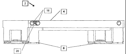
By way of introduction, Figures 1-3 schematically illustrate a number of the
principles of the dolly-pallet 2 of the present invention. According to the
teachings of
the present invention, the load bearing deck 4 may be alternately supported by
the
retractable support skid 6 or the wheel elements S. Further, the displacement
mechanism of the present invention provides a substantially locked support
state when
the load bearing deck 4 may be alternatel,y supported by the retractable
support skid 6
such that retractable support skid 6 is substantially locked from vertical
displacement
(as seen in Figures 6A, 7A and 9). Initial displacement of the skid during the
retraction
6
CA 02644924 2008-09-04
WO 2007/029231 PCT/IL2006/000955
process is along an upward substantially vet-tical path. In this way, the
center of mass
of the load is lowered vertically, thereby reducing stress on the displacement
mechanism, until the load is suppot-ted by the wheel elements 8. Once the
retractable
support skid 6 is retracted such that the dolly-pallet is being supported by
the wheel
elements 8, the retractable support skid 6 may be further displaced along an
upward
substantially arcuate path to move it away fonn the wheel elements 8, allowing
them
to swivel if they are so configured. Therefore, the two-stage displacement
motion
preferably corresponds to a high force/torque motion sufficient to the
retractable
support skid 6 when under load, followed by a low force/torque motion for
displacing
the unloaded retractable support skid 6 from the region of the wheels along
the arcuate
path.
It will be appreciated that only some of the wheel elements 8 may be
configured
to swivel. That is, to rotate about a vertical axis such as, but not 1'united
to, a caster.
Therefore, only those retractable support skids 6 associated with swivel wheel
elements 8s need be displaced further to allow the swivel wheel elements
freedom to
swivel. This is illustrated in Figure 3 where only retractable support skid 6a
is
displaced away fonn the wheel elements 8s.
It will be understood that directional terms such as "up," "upward," "doJA7n,"
"downward," "top," "bottom," "clockwise," and "counter-clock-Avise" are used
herein
in reference to those directions as they appear in the drawings.
Applying the principles of displacing the retractable support skids 6 first
along
an upward vertical path and then displacing the retractable support skids 6
fui-ther
along an upward arcuate path to move it away from the wheel elements 8 may be
achieved by any number of displacement mechanisms. Discussed herein are five
preferred embodiments offered as examples only. It will be apparent to one of
ordinary
skill in the art that other displacement mechanisms may be used with equal
success.
Although the embodiments illustrated herein are directed toward displacement
mechanisms and wheel elements that are deployed within an interior volume of a
fixed
leg portion extending downward from the load bearing deck of the dolly-pallet,
this is
considered to be a choice of design rather than a limitation, and the
principles of the
present invention may be applied without such an enclosure.
7
CA 02644924 2008-09-04
WO 2007/029231 PCT/IL2006/000955
It should be noted that for ease of understanding, displacement mechanism
elements that serve the same or similar function in each of the embodiments
herein
described are numbered the saine even though there may be slight differences
in their
individual configurations.
Referring now to the drawings, Figure 4 illustrates a first preferred
einbodiinent
of a displacement mechanism 10. In this embodiment, the retractable support
skid 6 is
retracted and lowered along a substantially vertical path by support struts
12, which are
attached to the rotating lifting bars 14 by eccentric attachinent shafts 16.
The rotating
lifting bars 14 are driven by gears 18 that mesh with drive gears 20 deployed
on drive
shaft 24.
Figures 6, 6A and 6B illustrate a variant 40 of the displacement mechanism of
Figure 4. Here, the gears 18 mesh with wonn gear 42, which is accessible from
the top
of the load bearing deck 4. Also seen clearly in figures 6A and 6B is the
process by
which the retractable support skid 6 is retracted and lowered along a
substantially
vertical path by support stiuts 12. The parallel support struts 12 are
pivotally attached
at one end to the retractable support skid 6 and at the other end to the
eccentric
attachinent shafts 16. As illustrated in Figure 6A, when the eccentric
attachinent shafts
16 are located at the bottom of their circular path, the retractable support
skid 6 is in
contact with the ground surface and supporting the dolly-pallet (as seen in
Figure 1).
As rotating lifting bars 14 rotate (here in a counter-clockwise direction) the
eccentric
attaclune.nt shafts 16 retract the retractable support skid 6 along a
substantially vertical
path bringing the wheel elements 8 into contact with the ground surface and
thereby
transferring support of the dolly-pallet from the retractable support skid 6
to the wheel
elements 8 (as seen in Figure 2).
As illustrated in Figures 4 and 4A, as the eccentric attachment shafts 16
reach
the top of their circular path, pins 22 engage the edge of support struts 12,
thereby
causing the support struts 12 to rotate with the rotating lifting bars 14 as
they continue
to rotate. This displaces the retractable support skid 6 along a substantially
arcuate path
up and away from the wheel elements 8, thereby allowing the wheel elements 8s
freedom to swivel (as seen in Figure 3).
8
CA 02644924 2008-09-04
WO 2007/029231 PCT/IL2006/000955
It will be appreciated that the retractable support skid 6 may be brought back
into contact wit11 the ground surface and the wheel elements 8 lifted, thereby
transferring support of the dolly-pallet from the wheel elements 8 back to the
retractable support skid 6 (as seen in Figure 1) by rotating the rotating
lifting bars 14 in
a clockwise direction and displacing the retractable support skid 6 first
along a
downward arcuate path toward the wheel elements 8, and then in a substantially
downward vertical path to the ground surface.
A second preferred embodiment of a displacement mechanism 60 is illustrated
in Figures 7, 7A, 7B, 8 and 8A. In this embodiment, the retractable support
skid 6 is
retracted and lowered along a substantially vertical path by support struts
12, which are
attached to levers 62 that extend from the rotating lifting bars 14. The
rotating lifting
bars 14 are driven by gears 18, which in this embodiment may be driven, by
either the
drive gears 20 deployed on drive shaft 22 of Figure 4, or the worm gear 42 of
Figure 6.
Figure 7A illustrates the position of the levers 62 when the retractable
support
skid 6 is in contact with the ground surface and supporting the dolly-pallet
(as seen in
Figure 1). As rotating lifting bars 14 rotate (here again in a counter-clock-
wise
direction) the levers 62 retract the retractable support skid 6 along a
substantially
vertical path bringing the wheel elements 8 into contact with the ground
surface and
thereby transferring support of the dolly-pallet from the retractable support
skid 6 to
the wheel elements 8 (as seen in Figure 2).
When the lifting projection 64 of the lever 62 engages the edge of support
struts
12 (Figure 7B), the support struts 12 begin to rotate with the rotating
liftirig bars 14 as
they continue to rotate. This displaces the retractable support skid 6 along a
substantially arcuate path up and away from the Nvheel elements 8 (Figure 8),
thereby
allowing the wheel elements Ss freedom to swivel (as seen in Figure 3).
An optional feature of the displacement mechanism of the present invention,
illustrated here in this embodiment of a displacement mechanism, is the
resilient snap-
lock arrangement 66 associated with the pivotal interconnection of the support
struts
12 and the lever 62. In a first snap-locking position, as seen in Figure 7A,
the resilient
snap-lock arrangement 66 helps maintain positional aligmnent betveen the
support
struts 12 and the lever 62 when the skid 6 is supporting the dolly-pallet and
during the
9
CA 02644924 2008-09-04
WO 2007/029231 PCT/IL2006/000955
displacement along the substantially vertical path. In a second snap-locking
position,
as seen in Figure 7B, the resilient snap-lock arrangement 66 helps maintain
positional
aligrunent between the support struts 12 and the lever 62 during displacement
of the
skid 6 along the substantially arcuate patll.
It will be appreciated that the retractable support skid 6 may be brought back
into contact with the ground surface and the wheel elements 8 lifted, thereby
transferring support of the dolly-pallet from the wheel elements 8 back to the
retractable support skid 6 (as seen in Figure 1) by rotating the rotating
lifting bars 14 in
a clockwise direction and displacing the retractable support skid 6 along a
downward
arcuate path toward the wheel elements 8, and then in a substantially downward
vertical path to the ground surface.
A manually operated "knockdown" variation of the second preferred
embodiment of a displacement mechanism 260 is illustrated in Figures 13-17. In
this
variation, the retractable support skid 6 is retracted and lowered along a
substantially
vertical path by support struts 12, which are pivotally attached to levers 62
that extend
from the rotating lifting bars 14. The rotating lifting bars 14. In this
variation, the
retractable support skid 6 is ulitial retracted from a position of supporting
the dolly-
pallet (as seen in Figures 1 and 13) by "knocking" release button 262, which
is
mechanically linked to at least on of the rotating lifting bars 14, with a
tool such as, but
not limited to, a harruner, thereby freeing the displacement mechanism 260
from a
locked position. This action also causes the release button to move laterally,
causing
rotation of rotating lifting bars 14, which may be mechanically linked by
gears such. as
is illustrated in Figure 5, thereby raising the retractable support skid 6
along a
substantially vertical path bringing the wheel elements 8 into contact with
the ground
surface and thereby transferring support of the dolly-pallet from the
retractable support
skid 6 to the wheel elements 8 (as seen in Figures 2, 14 and 15).
Displacement of the retractable support skid 6 along a substantially arcuate
path
up and away from the wheel elements 8, thereby allowing the wheel elements 8
freedom to swivel (as seen in Figures 3, 16 and 17) is accomplished by
rotating the
lifting lever 264, here, in a counter-clockwise direction, thereby rotating
the rotating
lifting bars 14. As lifting projection 64 of the lever 62 engages the edge of
support
CA 02644924 2008-09-04
WO 2007/029231 PCT/IL2006/000955
sti-uts 12 (Figure 17), the support struts 12 begin to rotate with the
rotating lifting bars
14.
It will be appreciated that the retractable support skid 6 may be brought back
into contact with the ground surface and the wheel elements 8 lifted, thereby
transferring support of the dolly-pallet from the wheel elements 8 back to the
retractable support skid 6 (as seen in Figures 1 and 13), by rotating the
lifting lever
264, and therefore, the rotating lifting bars 14 in a clock-wise direction and
displacing
the retractable support skid 6 along a downward arcuate path toward the wheel
elements 8, and then in a substantially downward vertical path to the ground
surface.
This will also bring the release button 262 back into its original position
and the
displacement mechanism 260 to a locked position, as illustrated in Figure 13.
It should be noted that Figures 15 and 17 illustrate two lifting levers 264
configured on opposite ends of one of the lifting bars 14. This is not
intended as a
limitation of the present invention, rather it is an example of one possible
configuration
within the scope of the present invention. It will be understood that a single
lifting
lever 264 would provide similar results.
A third preferred embodiment of a displacement mechanism 80 is illustrated in
Figures 9 and 9A. In this embodiment, the retractable support skid 6 is
retracted and
lowered along a substantially vertical path by support struts 12, which are
attached to
drive screws 82 that extend from drive gears 84, which are internally treaded
such that
drive screws 82 are raised and lowered by turning drive gears 84. The drive
gears 84
are driven by worm gears 86 configured on drive shaft 88.
As illustrated in Figures 9 and 9A the retractable support skid 6 is retracted
along a substantially vertical path from contact with the ground surface and
supporting
the dolly-pallet (as seen in Figure 1) by rotating drive shaft 88 in a counter-
clock-wise
direction. As the retractable support skid 6 retracts, the wheel elements 8
are brought
into contact with the ground surface, thereby transferring support of the
dolly-pallet
from the retractable support skid 6 to the wheel elements 8 (as seen in Figure
2). Since
support struts 12 are pivotally attached to drive screws 82, the retractable
support skid
6 may be displaced along a substantially arcuate path up and away from the
wheel
elements 8(Figure 8), thereby allowing the wheel elements 8 freedom to swivel
(as
11
CA 02644924 2008-09-04
WO 2007/029231 PCT/IL2006/000955
seen in Figure 3). This may be done manually or by any other suitable drive
mechanism (not shown).
It will be appreciated that the retractable support skid 6 may be brought back
into contact with the ground surface and the wheel elements 8 lifted, thereby
transferring support of the dolly-pallet from the wheel elements 8 back to the
retractable support skid 6 (as seen in Figure 1) by rotating drive shaft 88 in
a clockwise
direction and displacing the retractable support skid 6 along a substantially
downward
vertical path to the ground surface.
It should be noted that load bearing deck 4 may be configured. such that the
drive elements, such as the drive shaft 24, rotating lifting bars 14, and the
associated
gears, of these first three embodiments of displacement mechanisms of the
present
invention may be deployed within the structure of the load bearing deck 4
itself.
Alternatively, these drive elements may be attached to the underside of the
load
bearing deck 4.
Illustrated in Figures 10-12 is a four-th embodiment 100 of a displacement
mechanism by which the retractable support skid 6 is retracted and lowered
along a
substantially vertical path. In this embodiment, the retractable support skid
6 is
upwardly biased toward the legs 102 that extend downwardly from the load beard
deck
4 of the dolly-pallet. As seen in Figures 11 and 12, as wedges 104 are
displace
laterally, the retractable support skid 6 is drawn upward along a
substantially vertical
path toward the bottom surfaces of legs 102, thereby bringing the wheel
elements 8
into contact with the ground surface and transferring support of the dolly-
pallet from
the retractable support skid 6 to the wheel elements S.
It will be appreciated that the retractable support skid 6 may be brought back
into contact with the ground surface and the wheel elements 8 lifted, thereby
transferring support of the dolly-pallet from the wheel elements 8 back to the
retractable support skid 6 (as seen in Figure 1) by laterally displacing the
wedges 104
back into the region betNveen legs 102 and retractable support skid 6, thereby
displacing the retractable support skid 6 along a substantially downward
vertical path
to the ground surface.
12
CA 02644924 2008-09-04
WO 2007/029231 PCT/IL2006/000955
It should be noted that although the embodiments described herein make
reference to the retractable support skid 6 as the contact surface when the
dolly-pallet
of the present invention is deployed in a non-rollin6 state, this is not
intended as a
limitation and a dolly-pallet configured with individual retractable contact
surfaces
associated with each leg is within the scope of the present invention.
Further, it will be
understood that directions of rotation referred to in the illustrations herein
are by way
of example only and that actual direction of rotation is considered to be a
design
consideration. Further, although the displacement mechanisms described herein -
are
directed toward paired displacement mechanisms that are mechanically linked so
as to
be substantially simultaneously actuated by a coininon actuation linkage, this
need not
always be the case and individual actuation of each of the displacement
mechanisms is
within the scope of the present invention.
It will be appreciated that the displacement mechanism of the present
invention
may by driven manually or by a drive system, which may be in the fonn of an
onboard
drive system, or as a drive system accessory unit. Additionally, an onboard
drive
system may be activated via a control panel on the dolly-pallet, or remotely
via a
remote control system.
It will be appreciated that the above descriptions are intended only to serve
as
examples and that many other embodiments are possible within the spirit aild
the scope
of the present invention.
13