Language selection

Search

Patent 2644938 Summary

Third-party information liability

Some of the information on this Web page has been provided by external sources. The Government of Canada is not responsible for the accuracy, reliability or currency of the information supplied by external sources. Users wishing to rely upon this information should consult directly with the source of the information. Content provided by external sources is not subject to official languages, privacy and accessibility requirements.

Claims and Abstract availability

Any discrepancies in the text and image of the Claims and Abstract are due to differing posting times. Text of the Claims and Abstract are posted:

  • At the time the application is open to public inspection;
  • At the time of issue of the patent (grant).
(12) Patent Application: (11) CA 2644938
(54) English Title: SYSTEM FOR GENERATING POWER IN A PIPELINE
(54) French Title: INSTALLATION DE PRODUCTION D'ENERGIE DANS UN GAZODUC
Status: Deemed Abandoned and Beyond the Period of Reinstatement - Pending Response to Notice of Disregarded Communication
Bibliographic Data
(51) International Patent Classification (IPC):
  • F01D 15/10 (2006.01)
  • F01K 25/00 (2006.01)
  • F17D 01/04 (2006.01)
(72) Inventors :
  • BORLE, DEL (Canada)
(73) Owners :
  • DEL BORLE
(71) Applicants :
  • DEL BORLE (Canada)
(74) Agent: DOUGLAS B. THOMPSONTHOMPSON, DOUGLAS B.
(74) Associate agent:
(45) Issued:
(22) Filed Date: 2008-11-12
(41) Open to Public Inspection: 2010-05-12
Availability of licence: N/A
Dedicated to the Public: N/A
(25) Language of filing: English

Patent Cooperation Treaty (PCT): No

(30) Application Priority Data: None

Abstracts

English Abstract


A system for generating power includes an inline rotary turbine having an
input and
an output connected to a gas pipeline, such that gas flowing through the gas
pipeline rotates
the rotary turbine. A generator is connected to the inline rotary turbine for
generating power.
A bypass line has an input connected to the input of the rotary turbine and an
output
connected to the output of the rotary turbine. The bypass line has at least
one of an
electronically controlled flow control valve and a manually controlled flow
control valve.


Claims

Note: Claims are shown in the official language in which they were submitted.

4
What is Claimed is:
1. A system for generating power, comprising:
an inline rotary turbine having an input and an output connected to a gas
pipeline,
such that gas flowing through the gas pipeline rotates the rotary turbine;
a generator connected to the inline rotary turbine for generating power;
a bypass line connected to the gas pipeline for diverting a portion of gas
flow so that
portion of the gas flow bypasses the inline rotary turbine, the bypass line
having a flow
control valve, for selectively controlling the portion of gas flow passing
through the bypass
line.
2. The system of Claim 1, wherein a rotation sensor is positioned on one of
the inline rotary
turbine or the generator, the flow control valve is electronically actuated,
and a controller is
provided which receives data from the rotation sensor and electronically
actuates the flow
control valve to divert gas flow through the bypass line in accordance with a
flow control
strategy that keeps the rotations per minute of the inline rotary turbine
within a preselected
range.
3. The system of Claim 1, wherein the gas pipeline has an axis and the inline
rotary turbine is
axially offset.
4. The system of Claim 3, wherein the inline rotary turbine has radial vanes
that are movable
between an extended position and a retracted position, the radial vanes being
biased by
springs toward the extended position.

Description

Note: Descriptions are shown in the official language in which they were submitted.


CA 02644938 2009-01-12
TITLE
[0001] System for generating power in a pipeline
FIELD
[0002] Power generation for a pipeline .
BACKGROUND
[0003] U.S. patent no. 6,537,018 describes a rotational power transfer device.
SUMMARY
[0004] There is provided a system for generating power, comprising an inline
rotary
turbine having an input and an output connected to a gas pipeline, such that
gas flowing
through the gas pipeline rotates the rotary turbine. A generator is connected
to the inline
rotary turbine for generating power. A bypass line has an input connected to
the input of the
rotary turbine and an output connected to the output of the rotary turbine.
The bypass line has
at least one of an electronically controlled flow control valve and a manually
controlled flow
control valve.
13RIEF DESCRIPTION OF THE DRAWINGS
[0005] These and other features will become more apparent from the following
description in which reference is made to the appended drawings, the drawings
are for the
purpose of illustration only and are not intended to be in any way limiting,
wherein:
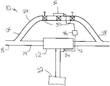
FIG. 1 is a schematic view of a system for generating power.
FIG. 2 is a side elevation view in section of an inline rotary turbine.
I)ETAILED DESCRIPTION
[0006] A system for generating power generally identified by reference numeral
10, will
now be described with reference to FIG. 1 and 2.
[0007] Referring to FIG. 1, system for generating power 10 includes an inline
rotary
turbine 12 having, referring to FIG. 2, an input 14 and an output 16 connected
to a gas
pipeline 18 as shown in FIG. 1, such that gas flowing through gas pipeline 18
rotates the
rotary turbine about an axis that is offset from the axis of gas pipeline 18.
Referring to FIG.

CA 02644938 2009-01-12
2
2, rotary turbine 12 includes a rotor 20 and spring-loaded vanes 21 that are
movable between
an extended position and a retracted position. Radial vanes 21 are biased by
springs 23
toward the extended position.
[0008] Referring to FIG. 1, a generator 22 is connected to inline rotary
turbine 12 for
generating power. There is a bypass line 24 that has an input 26 connected to
input 14 of
rotary turbine 12 and an output 28 connected to output 16 of rotary turbine
12. Bypass line is
connected to gas pipeline 18 and is used to divert a portion of gas flow so
that the portion of
the gas flow bypasses inline rotary turbine 12. Bypass line 24 has a flow
control valve, such
as two manually controlled flow control valves 30 and an electronically
controlled flow
control valve 32 to selectively control the portion of gas flow passing
through bypass line 24
and thus control the speed of turbine 12. Either one or both of generator 22
and turbine 12
rnay have a rotation sensor 34 to determine whether the optimal operating
speed for turbine
12 is being achieved. Rotation sensor 34 is preferably positioned on one of
the inline rotary
turbine 12 as shown in FIG. 1 or generator 22. Flow control valve 32 is
electronically
actuated, and a controller 36 is provided that receives data from rotation
sensor 34 and
electronically actuates flow control valve 32 to divert gas flow through
bypass line 24 in
accordance with a flow control strategy that keeps the rotations per minute of
the inline rotary
turbine within a preselected range. In addition to the embodiment described
above, these
readings may also be displayed for manual control, or both.
[0009] The system is connected to the outlet of a gas well in order to use the
pressure and
flow of the gas to drive the vane-type motor. This motion is used to drive a
generator to
generate power. The speed of the motor is controlled with a bypass control
valve, which may
be controlled either manually or electronically. The power generated can be
used on site, and
any remaining power can be sold into the power grid without consuming any gas.
[0010] In this patent document, the word "comprising" is used in its non-
limiting sense to
rnean that items following the word are included, but items not specifically
mentioned are not
excluded. A reference to an element by the indefinite article "a" does not
exclude the
possibility that more than one of the element is present, unless the context
clearly requires that

CA 02644938 2009-01-12
3
there be one and only one of the elements.
[0011] The following claims are to be understood to include what is
specifically
illustrated and described above, what is conceptually equivalent, and what can
be obviously
substituted. Those skilled in the art will appreciate that various adaptations
and modifications
of the described embodiments can be configured without departing from the
scope of the
claims. The illustrated embodiments have been set forth only as examples and
should not be
taken as limiting the invention. It is to be understood that, within the scope
of the following
claims, the invention may be practiced other than as specifically illustrated
and described.

Representative Drawing
A single figure which represents the drawing illustrating the invention.
Administrative Status

2024-08-01:As part of the Next Generation Patents (NGP) transition, the Canadian Patents Database (CPD) now contains a more detailed Event History, which replicates the Event Log of our new back-office solution.

Please note that "Inactive:" events refers to events no longer in use in our new back-office solution.

For a clearer understanding of the status of the application/patent presented on this page, the site Disclaimer , as well as the definitions for Patent , Event History , Maintenance Fee  and Payment History  should be consulted.

Event History

Description Date
Time Limit for Reversal Expired 2011-11-14
Application Not Reinstated by Deadline 2011-11-14
Deemed Abandoned - Failure to Respond to Maintenance Fee Notice 2010-11-12
Application Published (Open to Public Inspection) 2010-05-12
Inactive: Cover page published 2010-05-11
Inactive: IPC assigned 2009-09-16
Inactive: First IPC assigned 2009-09-16
Filing Requirements Determined Compliant 2008-12-22
Inactive: Filing certificate - No RFE (English) 2008-12-22
Application Received - Regular National 2008-12-22
Small Entity Declaration Determined Compliant 2008-11-12

Abandonment History

Abandonment Date Reason Reinstatement Date
2010-11-12

Fee History

Fee Type Anniversary Year Due Date Paid Date
Application fee - small 2008-11-12
Owners on Record

Note: Records showing the ownership history in alphabetical order.

Current Owners on Record
DEL BORLE
Past Owners on Record
None
Past Owners that do not appear in the "Owners on Record" listing will appear in other documentation within the application.
Documents

To view selected files, please enter reCAPTCHA code :


To view images, click a link in the Document Description column. To download the documents, select one or more checkboxes in the first column and then click the "Download Selected in PDF format (Zip Archive)" or the "Download Selected as Single PDF" button.

List of published and non-published patent-specific documents on the CPD .

If you have any difficulty accessing content, you can call the Client Service Centre at 1-866-997-1936 or send them an e-mail at CIPO Client Service Centre.


Document
Description 
Date
(yyyy-mm-dd) 
Number of pages   Size of Image (KB) 
Description 2009-01-11 3 100
Abstract 2009-01-11 1 12
Drawings 2009-01-11 1 13
Claims 2009-01-11 1 29
Representative drawing 2010-04-13 1 6
Filing Certificate (English) 2008-12-21 1 156
Reminder of maintenance fee due 2010-07-12 1 113
Courtesy - Abandonment Letter (Maintenance Fee) 2011-01-06 1 173
Correspondence 2008-12-21 1 55
Correspondence 2008-12-21 1 16
Correspondence 2010-07-12 1 38
Correspondence 2011-01-06 1 96