Sélection de la langue

Search

Sommaire du brevet 2644938 

Énoncé de désistement de responsabilité concernant l'information provenant de tiers

Une partie des informations de ce site Web a été fournie par des sources externes. Le gouvernement du Canada n'assume aucune responsabilité concernant la précision, l'actualité ou la fiabilité des informations fournies par les sources externes. Les utilisateurs qui désirent employer cette information devraient consulter directement la source des informations. Le contenu fourni par les sources externes n'est pas assujetti aux exigences sur les langues officielles, la protection des renseignements personnels et l'accessibilité.

Disponibilité de l'Abrégé et des Revendications

L'apparition de différences dans le texte et l'image des Revendications et de l'Abrégé dépend du moment auquel le document est publié. Les textes des Revendications et de l'Abrégé sont affichés :

  • lorsque la demande peut être examinée par le public;
  • lorsque le brevet est émis (délivrance).
(12) Demande de brevet: (11) CA 2644938
(54) Titre français: INSTALLATION DE PRODUCTION D'ENERGIE DANS UN GAZODUC
(54) Titre anglais: SYSTEM FOR GENERATING POWER IN A PIPELINE
Statut: Réputée abandonnée et au-delà du délai pour le rétablissement - en attente de la réponse à l’avis de communication rejetée
Données bibliographiques
Abrégés

Abrégé anglais


A system for generating power includes an inline rotary turbine having an
input and
an output connected to a gas pipeline, such that gas flowing through the gas
pipeline rotates
the rotary turbine. A generator is connected to the inline rotary turbine for
generating power.
A bypass line has an input connected to the input of the rotary turbine and an
output
connected to the output of the rotary turbine. The bypass line has at least
one of an
electronically controlled flow control valve and a manually controlled flow
control valve.

Revendications

Note : Les revendications sont présentées dans la langue officielle dans laquelle elles ont été soumises.


4
What is Claimed is:
1. A system for generating power, comprising:
an inline rotary turbine having an input and an output connected to a gas
pipeline,
such that gas flowing through the gas pipeline rotates the rotary turbine;
a generator connected to the inline rotary turbine for generating power;
a bypass line connected to the gas pipeline for diverting a portion of gas
flow so that
portion of the gas flow bypasses the inline rotary turbine, the bypass line
having a flow
control valve, for selectively controlling the portion of gas flow passing
through the bypass
line.
2. The system of Claim 1, wherein a rotation sensor is positioned on one of
the inline rotary
turbine or the generator, the flow control valve is electronically actuated,
and a controller is
provided which receives data from the rotation sensor and electronically
actuates the flow
control valve to divert gas flow through the bypass line in accordance with a
flow control
strategy that keeps the rotations per minute of the inline rotary turbine
within a preselected
range.
3. The system of Claim 1, wherein the gas pipeline has an axis and the inline
rotary turbine is
axially offset.
4. The system of Claim 3, wherein the inline rotary turbine has radial vanes
that are movable
between an extended position and a retracted position, the radial vanes being
biased by
springs toward the extended position.

Description

Note : Les descriptions sont présentées dans la langue officielle dans laquelle elles ont été soumises.

CA 02644938 2009-01-12
TITLE
[0001] System for generating power in a pipeline
FIELD
[0002] Power generation for a pipeline .
BACKGROUND
[0003] U.S. patent no. 6,537,018 describes a rotational power transfer device.
SUMMARY
[0004] There is provided a system for generating power, comprising an inline
rotary
turbine having an input and an output connected to a gas pipeline, such that
gas flowing
through the gas pipeline rotates the rotary turbine. A generator is connected
to the inline
rotary turbine for generating power. A bypass line has an input connected to
the input of the
rotary turbine and an output connected to the output of the rotary turbine.
The bypass line has
at least one of an electronically controlled flow control valve and a manually
controlled flow
control valve.
13RIEF DESCRIPTION OF THE DRAWINGS
[0005] These and other features will become more apparent from the following
description in which reference is made to the appended drawings, the drawings
are for the
purpose of illustration only and are not intended to be in any way limiting,
wherein:
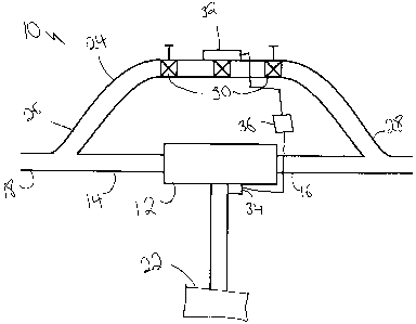
FIG. 1 is a schematic view of a system for generating power.
FIG. 2 is a side elevation view in section of an inline rotary turbine.
I)ETAILED DESCRIPTION
[0006] A system for generating power generally identified by reference numeral
10, will
now be described with reference to FIG. 1 and 2.
[0007] Referring to FIG. 1, system for generating power 10 includes an inline
rotary
turbine 12 having, referring to FIG. 2, an input 14 and an output 16 connected
to a gas
pipeline 18 as shown in FIG. 1, such that gas flowing through gas pipeline 18
rotates the
rotary turbine about an axis that is offset from the axis of gas pipeline 18.
Referring to FIG.

CA 02644938 2009-01-12
2
2, rotary turbine 12 includes a rotor 20 and spring-loaded vanes 21 that are
movable between
an extended position and a retracted position. Radial vanes 21 are biased by
springs 23
toward the extended position.
[0008] Referring to FIG. 1, a generator 22 is connected to inline rotary
turbine 12 for
generating power. There is a bypass line 24 that has an input 26 connected to
input 14 of
rotary turbine 12 and an output 28 connected to output 16 of rotary turbine
12. Bypass line is
connected to gas pipeline 18 and is used to divert a portion of gas flow so
that the portion of
the gas flow bypasses inline rotary turbine 12. Bypass line 24 has a flow
control valve, such
as two manually controlled flow control valves 30 and an electronically
controlled flow
control valve 32 to selectively control the portion of gas flow passing
through bypass line 24
and thus control the speed of turbine 12. Either one or both of generator 22
and turbine 12
rnay have a rotation sensor 34 to determine whether the optimal operating
speed for turbine
12 is being achieved. Rotation sensor 34 is preferably positioned on one of
the inline rotary
turbine 12 as shown in FIG. 1 or generator 22. Flow control valve 32 is
electronically
actuated, and a controller 36 is provided that receives data from rotation
sensor 34 and
electronically actuates flow control valve 32 to divert gas flow through
bypass line 24 in
accordance with a flow control strategy that keeps the rotations per minute of
the inline rotary
turbine within a preselected range. In addition to the embodiment described
above, these
readings may also be displayed for manual control, or both.
[0009] The system is connected to the outlet of a gas well in order to use the
pressure and
flow of the gas to drive the vane-type motor. This motion is used to drive a
generator to
generate power. The speed of the motor is controlled with a bypass control
valve, which may
be controlled either manually or electronically. The power generated can be
used on site, and
any remaining power can be sold into the power grid without consuming any gas.
[0010] In this patent document, the word "comprising" is used in its non-
limiting sense to
rnean that items following the word are included, but items not specifically
mentioned are not
excluded. A reference to an element by the indefinite article "a" does not
exclude the
possibility that more than one of the element is present, unless the context
clearly requires that

CA 02644938 2009-01-12
3
there be one and only one of the elements.
[0011] The following claims are to be understood to include what is
specifically
illustrated and described above, what is conceptually equivalent, and what can
be obviously
substituted. Those skilled in the art will appreciate that various adaptations
and modifications
of the described embodiments can be configured without departing from the
scope of the
claims. The illustrated embodiments have been set forth only as examples and
should not be
taken as limiting the invention. It is to be understood that, within the scope
of the following
claims, the invention may be practiced other than as specifically illustrated
and described.

Dessin représentatif
Une figure unique qui représente un dessin illustrant l'invention.
États administratifs

2024-08-01 : Dans le cadre de la transition vers les Brevets de nouvelle génération (BNG), la base de données sur les brevets canadiens (BDBC) contient désormais un Historique d'événement plus détaillé, qui reproduit le Journal des événements de notre nouvelle solution interne.

Veuillez noter que les événements débutant par « Inactive : » se réfèrent à des événements qui ne sont plus utilisés dans notre nouvelle solution interne.

Pour une meilleure compréhension de l'état de la demande ou brevet qui figure sur cette page, la rubrique Mise en garde , et les descriptions de Brevet , Historique d'événement , Taxes périodiques et Historique des paiements devraient être consultées.

Historique d'événement

Description Date
Le délai pour l'annulation est expiré 2011-11-14
Demande non rétablie avant l'échéance 2011-11-14
Réputée abandonnée - omission de répondre à un avis sur les taxes pour le maintien en état 2010-11-12
Demande publiée (accessible au public) 2010-05-12
Inactive : Page couverture publiée 2010-05-11
Inactive : CIB attribuée 2009-09-16
Inactive : CIB en 1re position 2009-09-16
Exigences de dépôt - jugé conforme 2008-12-22
Inactive : Certificat de dépôt - Sans RE (Anglais) 2008-12-22
Demande reçue - nationale ordinaire 2008-12-22
Déclaration du statut de petite entité jugée conforme 2008-11-12

Historique d'abandonnement

Date d'abandonnement Raison Date de rétablissement
2010-11-12

Historique des taxes

Type de taxes Anniversaire Échéance Date payée
Taxe pour le dépôt - petite 2008-11-12
Titulaires au dossier

Les titulaires actuels et antérieures au dossier sont affichés en ordre alphabétique.

Titulaires actuels au dossier
DEL BORLE
Titulaires antérieures au dossier
S.O.
Les propriétaires antérieurs qui ne figurent pas dans la liste des « Propriétaires au dossier » apparaîtront dans d'autres documents au dossier.
Documents

Pour visionner les fichiers sélectionnés, entrer le code reCAPTCHA :


Pour visualiser une image, cliquer sur un lien dans la colonne description du document. Pour télécharger l'image (les images), cliquer l'une ou plusieurs cases à cocher dans la première colonne et ensuite cliquer sur le bouton "Télécharger sélection en format PDF (archive Zip)" ou le bouton "Télécharger sélection (en un fichier PDF fusionné)".

Liste des documents de brevet publiés et non publiés sur la BDBC .

Si vous avez des difficultés à accéder au contenu, veuillez communiquer avec le Centre de services à la clientèle au 1-866-997-1936, ou envoyer un courriel au Centre de service à la clientèle de l'OPIC.


Description du
Document 
Date
(aaaa-mm-jj) 
Nombre de pages   Taille de l'image (Ko) 
Description 2009-01-11 3 100
Abrégé 2009-01-11 1 12
Dessins 2009-01-11 1 13
Revendications 2009-01-11 1 29
Dessin représentatif 2010-04-13 1 6
Certificat de dépôt (anglais) 2008-12-21 1 156
Rappel de taxe de maintien due 2010-07-12 1 113
Courtoisie - Lettre d'abandon (taxe de maintien en état) 2011-01-06 1 173
Correspondance 2008-12-21 1 55
Correspondance 2008-12-21 1 16
Correspondance 2010-07-12 1 38
Correspondance 2011-01-06 1 96