Note: Descriptions are shown in the official language in which they were submitted.
CA 02644978 2010-02-26
TRAILER FOR TRANSPORTING GOLF CARTS AND RECREATIONAL
VEHICLES
This invention relates to a trailer for transporting vehicles such as golf
carts and recreational vehicles (ATVs) where the width of the vehicle to be
transported is such that they are too wide to be transported side by side and
are
sufficiently low in height such that they can be stacked one above another.
BACKGROUND OF THE INVENTION
Manufactures and distributors of golf carts and recreational vehicles
ATVs of the type where two passengers sit side by side need a way to
economically
transport un-crated vehicles of various sizes from their factories to
distributors and
dealers world wide. These vehicles are generally of the order of 5 feet in
width so
that they cannot be loaded side by side in a conventional trailer.
Shipping golf carts and larger ATVs from the manufactures to dealers
and distributors in semi-trailers and without crating provides significant
savings to
both the manufactures and dealer/ distributor by eliminating the cost of
constructing
"one time use" crates and substantially reducing freight costs and fuel
emissions by
transporting double the freight in one haul.
Another benefit of this transportation is that it also eliminates the dealer
personnel having to unload crated vehicles using forklifts or similar
arrangements.
This also can reduce the damage and warranty claims for damages since the
equipment transported is available for immediate visual inspection rather than
waiting until the equipment is un-crated at the time of sale to a customer.
CA 02644978 2010-02-26
2
A standard semi-trailer is 53 ft long, 8 ft 6 inches wide and from floor to
ceiling is approx 9 ft 2 inches in height. These dimensions are such that the
hauling
capacity can be doubled if a multi tier system is installed which provides
stacking of
un-crated vehicles within the semi-trailer.
It is clear that a dedicated semi-trailer could be modified or constructed
with a fixed deck between the floor and roof of the semi-trailer but this
prevents the
use of the trailer for shipping other general freight than the product for
which it is
designed and dedicated.
In US Patent 6,524,055 (Overbye) issued February 25, 2003 is
disclosed a modification of a trailer for transporting vehicles of this
general type in
which the trailer includes a plurality of logistics posts along the sides on
which are
mounted a series of E-bars at spaced positions along the trailer. The E-bars
span
the trailer and support left, center and right tracks installed along the
length of the
trailer onto which the vehicles are rolled and are carried. This provides
therefore a
second row of transportation for the vehicles located above the trailer floor.
A ramp
structure is provided which allows the vehicles to be rolled into place either
on the
floor or on the second row. In order to convert the trailer from transporting
the
vehicles to transporting general cargo, the ramps must be removed and stored.
In US Patent 4,786,222 (Blodgett) issued November 22, 1988 is
disclosed a trailer designed for transporting automobiles in two rows.
CA 02644978 2010-02-26
3
SUMMARY OF THE INVENTION
It is one object of the invention to provide a trailer for transporting
vehicles such as golf carts and wider ATVs.
According to one aspect of the invention there is provided a transport
trailer for transporting vehicles comprising:
a trailer body with a floor, two side walls and a roof with a rear opening
for loading an interior of the trailer body;
the trailer body being mounted on ground wheels with a front
connection for towing of the trailer for transporting cargo contained within
the trailer
body;
and an apparatus for increasing the load capacity of the trailer body
when used transporting golf carts recreational vehicles comprising:
a plurality of upstanding logistic posts at spaced positions along the
side walls of the trailer;
plurality of beams each connected across the trailer and removably
supported on the posts;
a foldable platform at a height part way between the floor and the roof;
the platform being formed of a plurality of panels;
each panel connected with an outer edge thereof hingedly mounted to
a respective one of the side walls of the trailer;
the panels being pivotally movable about a hinge line at the respective
side wall;
CA 02644978 2010-02-26
4
the panels thus defining an operating position in which the panels
extend part way across the trailer to form a horizontal support carried on the
beams;
the panels thus defining a stored position in which the panels extend
substantially vertically along the respective side wall of the trailer;
the panels being separate from the beams such that the panels are
movable to the stored position while the beams remain connected across the
posts;
and a ramp assembly arranged to extend rearwardly of the rear
opening of the trailer to the ground for loading the vehicles;
the ramp assembly being arranged to cooperate with the floor and with
the horizontal support formed by the panels for loading the vehicles on the
floor and
on the horizontal support.
Preferably the panels are arranged such that in the operating position
the panels on one side wall meet the panels on the other side wall at the
inner edges
thereof, thus leaving no open area along the center. However the panels may
also
be of reduced width so that a space is allowed, provided the space is
sufficiently
small that the wheels of the vehicles are received on the panels.
Preferably the panels are connected to the respective side wall such
that in the stored position the panels extend vertically upwardly along the
respective
side wall.
Preferably each panel includes a latch to locate the panel at the
respective side wall in the stored position.
CA 02644978 2010-02-26
Preferably the panels are conveniently made of plywood, although
other materials such as plastics sheeting can be used.
Preferably the ramp assembly includes a front ramp section, a rear
ramp section and a center stabilizer stanchion between the front and rear
sections to
5 support a front end of the rear section and a rear end of the front section
in an
elevated position.
Preferably each of the ramp sections includes a pair of ramp members
which are adjustable in spacing to accommodate different wheel spacing of the
vehicles.
Preferably the ramp members of the front ramp section are arranged to
attach to the truck floor at a rear cross member and to a rear beam of the
beams.
Preferably the ramp sections are attached to the center stabilizer
stanchion by a safety rod.
Preferably the ramp assembly includes four ramp members which are
stored when not in use in a rack under the trailer floor.
Preferably the rack includes front and rear holders arranged to hold the
ramp members parallel and side by side with a top surface of each ramp member
vertical.
This arrangement described herein thus provides a permanently
mounted collapsible elevated floor system, two tier ramp system with
adjustable
receivers and ramp stabilizers complete with on-board storage rack. This
arrangement facilitates the loading, securement and transporting of motorized
golf
CA 02644978 2010-02-26
6
carts and side by side recreational vehicles in conventional semi-trailers
used for
hauling general freight.
Therefore it is desirable to provide a collapsible floor system that can
be readily stored on the walls via a permanent mount hinge system with upper
pin
lock to secure the collapsible floor while in storage mode, thus allowing the
trailer to
be used for general freight transportation. With the collapsible floor system
being
constructed the full width of the trailer on a solid platform it allows for
the
transportation of various sized vehicles with a max width of 90 inches and
overall
length of the trailer which is approx 52 feet or on average 26 golf carts
verses 13 for
conventional transport systems and 10 ATVs verses 5 for the conventional
system.
BRIEF DESCRIPTION OF THE DRAWINGS
One embodiment of the invention will now be described in conjunction
with the accompanying drawings in which:
Figure 1 is a side elevational view of a trailer according to the present
invention showing the trailer being loaded to an upper row on a horizontal
upper
support.
Figure 2 is a side elevational view of the trailer of Figure 1 showing the
trailer being loaded to a lower row at the floor.
Figure 3 is a side elevational view of the trailer of Figure 1 showing the
trailer with the ramps in storage position.
Figure 4 is a cross sectional view of the trailer taken along the lines A-
A of Figure 3.
CA 02644978 2010-02-26
7
Figure 5 is a cross sectional view of the trailer taken along the lines B-
B of Figure 3.
Figure 6 is a cross sectional view of the trailer taken along the lines C-
C of Figure 3.
Figure 7 is a side elevational view of the trailer of the center stabilizer
stanchion of Figure 1.
Figure 8 is a rear elevational view of the trailer of Figure 1.
Figure 9 is a plan view of the connection between the ramps and the
center stabilizer stanchion of Figure 7.
Figure 10 is a cross sectional view of the trailer showing the panels of
Figure 1.
Figure 11 is a cross sectional view of the trailer taken along the lines
G-G of Figure 1.
Figure 12 is a cross sectional view taken along the lines H-H of Figure
11.
In the drawings like characters of reference indicate corresponding
parts in the different figures.
DETAILED DESCRIPTION
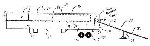
The invention of the present invention comprises a trailer 10 having a
frame not shown on which is mounted a trailer box defined by a floor 11, side
walls
12 and a roof 13. These provide an open rear 14 which can be closed by
suitable
doors as is well known. The trailer includes a hitch arrangement at the
forward end
CA 02644978 2010-02-26
8
and ground wheels 15 for transporting the trailer. Particularly the trailer is
a semi-
trailer so that the hitch forward end provides a king pin arrangement for
attachment
to a highway tractor.
In general the transport arrangement of the trailer includes a first row
16 for receiving the vehicles to be transported on the floor 11 and a second
row 17
for receiving a further number of the vehicles to be transported carried on a
support
surface 18 defined by a plurality of panels 19. In addition the system
comprises a
loading ramp assembly 20 defined by a front ramp section 21, a rear ramp
section
22 and a centre stabilizer stanchion 23.
In Figure 1 it will be noted that the ramp assembly is arranged for
loading the vehicles onto the upper row 17. In Figure 2 the ramp assembly 20
is
arranged for loading the vehicles onto the lower row 16 that is onto the floor
11.
This adjustment is obtained by moving a forward end 24 of the front ramp
section
from a rear cross member 25 at the floor to a rear beam 26 at the support 18.
As shown in Figures 4 and 5, the upper support 18 is defined by
panels 19 each of which has an outer edge 27 connected to the side wall 12 of
the
truck body by a hinge 28. The hinge 28 allows the panel to move from the
horizontal
position shown in Figure 5 to a vertical raised position shown in Figure 4. In
the
raised position the panel stands along the side wall of the truck body to a
position
closely adjacent the roof 13. The panel includes a spring latch 29 with a pin
30
which engages into a hole in a flange 31 attached to the side wall 12 adjacent
the
roof 13. The spring latch 29 is on the underside of the panel. The panels are
CA 02644978 2010-02-26
9
conventional plywood sheeting of dimensions 4 feet by 8 feet so that an inner
edge
32 of the panel 19 lies closely adjacent or meets an inner edge 32 of an
opposed
panel 19A at the opposite side wall 12A. The panels remain in place in the
horizontal position simply by gravity and the latches 29 are not used in the
lowered
operating position shown in Figure 5. The panels are carried on a series of
transverse beams 33 at spaced positions along the truck body. Each of these
beams spans across the width of the truck body and is supported at its ends on
a
plurality of logistics posts 34 also at spaced positions along the truck body.
Such logistic posts are well known in the trucking industry and trucks
are suitably supplied when required containing the logistics posts. These
posts are
structural members which provide a supporting structure for attachment of
transverse beams or bars which can be located at various heights along the
posts.
These are conventionally used to engage or locate cargo within the truck box.
Thus
the posts each have a series of slots or holes into which the ends of the
beams can
be engaged to support the beam at a required height.
In this embodiment the beams 33 are located approximately at mid
height of the truck box and a full set of beams is provided which extends
across
each of the pairs of posts along the length of the truck body.
With the beams in place, the panels 19 can be pivoted simply
downwardly to lie over the beams and they are supported thereby to form a
subsidiary floor or support surface at a raised position relative to the floor
11. A plan
view of the subsidiary floor is shown in Figure 10 where the transverse beams
33
CA 02644978 2010-02-26
can be seen attached to the logistics posts 34 in the side walls 12 and 12A.
The ramp assembly best visible in Figures 7, 8 and 9 comprises an
upper ramp section 21 defined by a pair of ramp members 40 and 41. The lower
ramp section 22 is also defined by a pair of ramp members 43 and 44. Each of
the
5 ramp members is of a conventional construction defined by side beams 45 and
46
together with a plurality of transverse slats 47. The width of the ramp
members is
sufficient to receive the wheel of the vehicle to be loaded. The spacing 48
between
the ramp members of the upper and lower sections can be adjusted by moving the
ramp members inwardly and outwardly across the central stabilizer stanchion 23
and
10 across the rear of the truck body.
The central stanchion 23 comprises a base 49 for resting on a suitable
floor surface together with a pair of upstanding legs 50 at spaced positions
across
the base 49. Each of the legs 50 is braced by front and rear braces 51, 52 so
as to
be supported in vertical position when the base 49 sits in horizontal position
on the
ground. The height of the stanchion can be adjusted by sliding an inner tube
53
upwardly and downwardly with respect to the leg 50 and by locking the tube 53
at a
required height 55 within the tube defined by the leg. Thus an upper
transverse
beam 56 of the stanchion is supported at a required height relative to the
ground.
As best shown in Figure 7, the upper end of the lower ramp member 43 carries a
flange 57 for engagement with a receptacle 58 on the rear side of the beam 56.
Symmetrically a receptacle 59 is provided on the upper side of the beam 56 for
receiving a flange 60 of the upper ramp member 40.
CA 02644978 2010-02-26
11
The flanges 57 and 60 carry a tubular receiving portion 61, 62 into
which a respective pin 63, 64 can be received acting to lock the respective
flange to
the respective receptacle 58 and 59. Thus when the pins 63, 64 are inserted,
the
ramp members are fixed to the stanchion and are prevented against falling from
the
stanchion.
As shown in Figures 1 and 2, the stanchion is adjusted in height so
that the first ramp section at the lower end extends from the ground to a
height
approximately equal to the floor 11. The upper ramp section then extends from
the
stanchion to the truck and in the loading position where it is loading the
floor, the
upper ramp section is generally horizontal. This allows the upper ramp section
to be
inclined upwardly to the upper loading row from the top of the stanchion 23 at
an
angle which is approximately equal to the angle of the lower ramp section.
As shown in Figures 11 and 12 a symmetrical latching arrangement is
provided at the rear of the truck relative to the latching arrangement at the
top of the
stanchion 23. Thus the upper end of the upper ramp member 40 has also a flange
66 symmetrical to the flange 60 together with a receiving portion 67
symmetrical to
the receiving portion 62. This allows a pin 68 to engage through the receiving
portion from the receptacle 69 on the rear most one of the beams 33 as
indicated at
33A. Thus again the receiving portion 67 sits in the receptacle 69 and is
latched in
place by the transverse pin 68.
In this way the spacing between the ramp members can be adjusted
by sliding the ramp members horizontally across the stanchion and across the
rear
CA 02644978 2010-02-26
12
beam of the truck. The width of the pin and the width of the receptacle is
such that
the movement across the width of the truck is sufficient to accommodate the
difference in wheel spacing of the various vehicles to be loaded.
Although not shown, a symmetrical mounting arrangement is provided
on the rear cross member 25 at the floor of the truck.
Turning now to Figure 6, each of the four ramp members 40, 41, 43
and 44 if carried in a rack 70 defined by front and rear rack members 71 and
72.
The ramp members are carried in vertical orientation so that the slats 47
stand
vertically with the side beams 45 and 46 at top and bottom respectively of the
slats.
The rack defines a receiving area equal to the dimensions of the four rack
members
arranged side by side. A front cover portion 75 is inserted over the rack
members
when they are mounted in place on a bottom horizontal receiving rail 76 and
confined by a top receiving rail 77. Thus the racks ramp members are held
fixed in
place within the rack and clamped in position by the front cover 75 so that
they
extend along one side of the truck body underneath the frame of the truck body
and
underneath the floor 11 with the ramp members extending partly along the side
of
the truck body. The stanchion 23 after the ramp members have been removed can
simply be stored inside the truck box alongside the vehicles stored therein.
While the truck body is thus suitably configured to transport two rows
of the vehicles, it can simply and quickly be modified to transport
conventional cargo
by lifting the panels 19 to the upward stored position alongside the side
walls and
removing those of the transverse beams 33 that are required to allow the
insertion
CA 02644978 2010-02-26
13
and placement of the cargo to be transported. In the event that all of the
beams are
to be removed, the total number of beams can be stored simply within the
interior of
the truck body with the stanchion. When thus stored, preferably at the forward
end
of the truck, the remaining open area of the truck body is available
substantially
wholly between the side walls and between the floor and the ceiling for
receiving the
conventional cargo to be transported.
Since various modifications can be made in my invention as herein
above described, and many apparently widely different embodiments of same made
within the spirit and scope of the claims without department from such spirit
and
scope, it is intended that all matter contained in the accompanying
specification shall
be interpreted as illustrative only and not in a limiting sense.