Language selection

Search

Patent 2645192 Summary

Third-party information liability

Some of the information on this Web page has been provided by external sources. The Government of Canada is not responsible for the accuracy, reliability or currency of the information supplied by external sources. Users wishing to rely upon this information should consult directly with the source of the information. Content provided by external sources is not subject to official languages, privacy and accessibility requirements.

Claims and Abstract availability

Any discrepancies in the text and image of the Claims and Abstract are due to differing posting times. Text of the Claims and Abstract are posted:

  • At the time the application is open to public inspection;
  • At the time of issue of the patent (grant).
(12) Patent: (11) CA 2645192
(54) English Title: STATOR WINDING FOR A SLOTLESS MOTOR
(54) French Title: ENROULEMENT DE STATOR POUR MOTEUR SANS RAINURE
Status: Granted
Bibliographic Data
(51) International Patent Classification (IPC):
  • H02K 17/00 (2006.01)
  • H02K 19/00 (2006.01)
  • H02K 21/00 (2006.01)
(72) Inventors :
  • HAWES, DAVID E. (United States of America)
(73) Owners :
  • ALLIED MOTION TECHNOLOGIES INC. (United States of America)
(71) Applicants :
  • ALLIED MOTION TECHNOLOGIES INC. (United States of America)
(74) Agent: CASSAN MACLEAN IP AGENCY INC.
(74) Associate agent:
(45) Issued: 2012-05-01
(86) PCT Filing Date: 2006-03-07
(87) Open to Public Inspection: 2007-09-13
Examination requested: 2011-02-15
Availability of licence: N/A
(25) Language of filing: English

Patent Cooperation Treaty (PCT): Yes
(86) PCT Filing Number: PCT/US2006/008260
(87) International Publication Number: WO2007/102818
(85) National Entry: 2008-09-08

(30) Application Priority Data: None

Abstracts

English Abstract

A stator winding for a slotless motor is parallel with the longitudinal axis of the motor except at the end turns of the coil windings. The coils have concentrated windings with a pair of coils wired in series to form one phase of the stator windings. Each of the pair of coils are wound such that the magnetic flux produced by a dc current through the coils produces magnetic flux of opposite directions with respect to the rotor of the motor.


French Abstract

L'enroulement de stator pour moteur sans rainure selon l'invention est parallèle à l'axe longitudinal du moteur sauf aux tournants d'extrémité des enroulements de bobine. Les bobines présentent des enroulements concentrés avec une paire de bobines câblées en série pour former une phase des enroulements de stator. Chacune des paires de bobines est enroulée de telle sorte que le flux magnétique produit par un courant continu à travers les bobines, produise un flux magnétique de sens opposé par rapport au rotor du moteur.

Claims

Note: Claims are shown in the official language in which they were submitted.


WHAT IS CLAIMED IS:


1. A pair of coils for a slotless motor wound with a continuous wire and wired

as one phase of a three-phase stator, wherein the wire in the coils is
parallel with
the longitudinal axis of said stator except at the ends of said stator where
said wire
is bent along a curve orthogonal to said longitudinal axis having a radius
greater
than an inner radius of said stator.


2. The pair of coils set forth in claim 1, wherein the direction of the
magnetic
flux through the center of one of said coils is towards a region at least
partially
surrounded by said coils, and the magnetic flux through the center of one of
said
coils is away from a region at least partially surrounded by said coils.


3. A method of wiring a coil for a stator of a slotless motor comprising the
steps of:
a) placing a first portion of a wire on a cylindrical form such that said
first
portion is parallel with the longitudinal axis of said form;
b) placing a second portion of said wire substantially transverse to said
longitudinal axis, said second portion being arcuate with a radius of
curvature
greater than the radius of said form;
c) placing a third portion of said wire parallel with the longitudinal axis of

said form and being circumferentially offset from said first portion with
respect to the
circumference of said form;
d) placing a fourth portion of said wire substantially transverse to said
longitudinal axis, said third portion being arcuate with a radius of curvature
with
respect to said longitudinal axis that is greater than the radius of said form
and
having one end thereof in close proximity to an end of said first portion;
e) repeating steps a) thorough d) for a predetermined number of times;
f) then repeating steps a) through c) thereby forming a first coil;
g) repeating steps a) through f) to form a plurality of coils, each of said


7


coils having first and third portions which are each circumferentially offset
from all
other first and second portions.


4. The method set forth in claim 3 wherein one end of one coil is connected
to one end of a second coil to form one phase winding.


5. The method set forth in claim 4 wherein said ends of said one and second
coils connected together are selected such that a direct current flowing
through said
coils produces magnetic lines afflux which are toward a center of said coils
in one
of said coils and away from said center in the other of said coils.


6. A stator winding phase of a three-phase stator for a slotless motor that is

parallel with the longitudinal axis of the motor except at the end turns of
the
winding.


8

Description

Note: Descriptions are shown in the official language in which they were submitted.


CA 02645192 2008-09-08
WO 2007/102818 PCT/US2006/008260
STATOR WINDING FOR A SLOTLESS MOTOR

TECHNICAL FIELD

The present invention relates to slotless motors, and, more particularly,
to stator windings for a slotless motor.

BACKGROUND OF THE INVENTION

An application for slotless motors is for use in handheld medical
equipment. Makers of such motors strive to provide high speed, high torque
motors that can stay relatively cool under sustained full load operation. In
the
past the stator coils in these slotless motors have been twisted around the
longitudinal axis of the motor for various reasons. U.S. Patent 4,733,118 to

Mikalko describes such a stator winding and one reason for the twisted coils.
What is needed is a stator coil that provides improved performance for
such slotless motors compared to slotless motors with twisted stator windings.

It is a principal object of the present invention to provide a stator coil
that provides improved performance for such slotless motors compared to
slotless motors with twisted stator windings.

SUMMARY OF THE INVENTION

Briefly described, in one embodiment of the present invention a pair of
coils for a slotless motor are wired as one phase of a stator wherein the
wires


CA 02645192 2008-09-08
WO 2007/102818 PCT/US2006/008260
in the coils are parallel with the longitudinal axis of the stator except at
the

ends of the stator where the wires are bent along a curve orthogonal to the
longitudinal axis having a radius equal to or greater than an inner radius of
the
stator.

Also described in one embodiment of the present invention is a method
of wiring a coil for a stator of a slotless motor by a) placing a first
portion of a
wire on a cylindrical form such that the first portion is parallel with the

longitudinal axis of the form; b) placing a second portion of the wire
substantially transverse to the longitudinal axis, the second portion being
arcuate with a radius of curvature greater than the radius of the form; c)

piacing a third portion of the wire parallel with the longitudinal axis of the
form
and being circumferentially offset from the first portion with respect to the
circumference of the form; and d) placing a fourth portion of the wire
substantially transverse to the longitudinal axis, the third portion being
arcuate

with a radius of curvature with respect to the longitudinal axis that is
greater
than the radius of the form and having one end thereof in close proximity to
an
end of the first portion. Steps a) thorough d) are repeated for a
predetermined
number of times, and then steps a) through c) are repeated to thereby form a
first coil.

The steps in the above paragraph are repeated to form a plurality of
coils, each of the coils having first and third portions which are each
circumferentially offset from all other first and second portions.

Further described in one embodiment of the present invention is a
stator winding for a slotiess motor that is parallel with the longitudinal
axis of
the motor except at the end turns of the winding.

2


CA 02645192 2008-09-08
WO 2007/102818 PCT/US2006/008260
BRIEF DESCRIPTION OF THE DRAWINGS

The accompanying drawings, which are incorporated into and form a
part of the specification, illustrate several embodiments of the present

invention, and together with the description, serve to explain the principles
of
the invention. The drawings are only for the purpose of illustrating a
preferred
embodiment of the invention and are not to be construed as limiting the
invention. In the drawings:

FIG. I is a perspective view of a slotless motor suitable for use in
handheld medical equipment having a stator coil according to one
embodiment of the present invention;

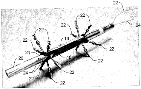
FIG. 2 is a perspective view of two coils in the siotiess motor shown in
FIG. 1 on a form used to wind the coils;

FIG. 3 is a perspective view of a completed stator used in the slotless
motor shown in FIG. 1; and

FIG. 4 is a graph of typical speed and torque characteristics of the type
of motor shown in FIG. 1.

It will be appreciated that for purposes of clarity and where deemed
appropriate the various elements in the drawings have not necessarily been
drawn to scale in order to better show the features of the invention.

DESCRIPTION OF THE PREFERRED EMBODIMENTS

Turning now to the drawings FIG. 1 shows a perspective view of a
slotless motor 10 suitable for use in handheld medical equipment having a
3


CA 02645192 2008-09-08
WO 2007/102818 PCT/US2006/008260
stator coil according to one embodiment of the present invention. An inline
gearbox 12 is attached to the motor, and a group of wires 14 provides
connections to the three phases of the motor as well as to rotor position

sensing electronics (not shown). The motor 10 is about 1 1/2 inches long with
a diameter of about 1/2 Inches making it of a size suitable for handheld
medical equipment.

FIG. 2 is a perspective view of two coils 16 and 18 in the slotless motor
shown in FIG. 1. The coils 16, 18 are wound on.a cylindrical form 20
which has twelve posts 22 inserted into holes 24 in the outer surface of the

10 form 20 and around which the wire for the coils is wound. The coils 16, 18
lie
parallel to the longitudinal axis of the form 20 (and therefore parallel to
the
longitu.dinal axis of the motor 10) except at the ends of the coils. Also the
coils have concentrated windings to provide short end turns. By using coils
that are parallel to the longitudinal axis rather than being twisted, the
magnetic

interaction between the rotor (not shown) and the coils 16, 18 is
orthogonal'to
the coils 16, 18 thereby producing more back EMF in the coils 16, 18 than in
twisted coils. As a result, the speed of the motor is improved, and the number
of turns in each coil can be reduced thereby decreasing the losses in the end
turns. Also, the decrease in the number of turns means a lower resistance in
each coil which provides the motor 10 with greater torque compared to

slotless motors with twisted coils. In addition, the lower current means lower
12R losses which decreases the heat generated by the motor. Finally, the
coils 16, 18 result in a flatter curve for the torque and speed of the motor
compared to slotiess motors with twisted coils.

The coils 16, 18 are wired in series and form one phase of a three
4


CA 02645192 2008-09-08
WO 2007/102818 PCT/US2006/008260
phase motor in the embodiment shown in FIG. 1. The ends 22 and 24 are the
connections to the single phase formed by the coils 16, 18. In the preferred
embodiment the single phase formed by coils 16, 18 has one end 22, 24
thereof connected at the neutral or common node of a Wye connection of the

three phases A, B, and C. The rotor in the preferred embodiment is a 2-pole
rotor. The two coils 16, 18 are in series and reversed in polarity producing a
positive or negative back EMF due to the 2-pole rotor. The actual back EMF
from Phase A to Phase B (or C) is a phasor sum of these back EMF's.

The two other phases have coils arranged as shown in FIG. 2 except
that they are offset from the two coils 16, 18 by 600. Thus, each of the three
phases of the stator overlap each of the other phases in the conventional
manner.

FIG. 3 is a perspective view of a completed stator 30 wherein the
windings are covered with a thin insulator 32, and laminated rings 34 of
permeable metal are slipped over the thin insulation 32.

FIG. 4 is a graph of typical speed and torque characteristics of the type
of motor shown in FIG. 1. As can be seen, the speed across the torque range
of 0 to 5 Oz-lns is fairly flat as is the current drawn by the motor 10 across
the
torque range.

The embodiment described is chosen to provide an illustration of
principles of the invention and its practical application to enable thereby
one
of ordinary skill in the art to utilize the invention in various embodiments
and
with various modifications as are suited to the particular use contemplated.
Therefore, the foregoing description is to be considered exemplary, rather

than limiting, and the true scope of the invention is that described in the
5


CA 02645192 2008-09-08
WO 2007/102818 PCT/US2006/008260
following claims.

6

Representative Drawing
A single figure which represents the drawing illustrating the invention.
Administrative Status

For a clearer understanding of the status of the application/patent presented on this page, the site Disclaimer , as well as the definitions for Patent , Administrative Status , Maintenance Fee  and Payment History  should be consulted.

Administrative Status

Title Date
Forecasted Issue Date 2012-05-01
(86) PCT Filing Date 2006-03-07
(87) PCT Publication Date 2007-09-13
(85) National Entry 2008-09-08
Examination Requested 2011-02-15
(45) Issued 2012-05-01

Abandonment History

There is no abandonment history.

Maintenance Fee

Last Payment of $458.08 was received on 2022-02-18


 Upcoming maintenance fee amounts

Description Date Amount
Next Payment if small entity fee 2023-03-07 $253.00
Next Payment if standard fee 2023-03-07 $624.00

Note : If the full payment has not been received on or before the date indicated, a further fee may be required which may be one of the following

  • the reinstatement fee;
  • the late payment fee; or
  • additional fee to reverse deemed expiry.

Patent fees are adjusted on the 1st of January every year. The amounts above are the current amounts if received by December 31 of the current year.
Please refer to the CIPO Patent Fees web page to see all current fee amounts.

Payment History

Fee Type Anniversary Year Due Date Amount Paid Paid Date
Application Fee $400.00 2008-09-08
Maintenance Fee - Application - New Act 2 2008-03-07 $100.00 2008-09-08
Registration of a document - section 124 $100.00 2008-12-11
Maintenance Fee - Application - New Act 3 2009-03-09 $100.00 2009-03-04
Maintenance Fee - Application - New Act 4 2010-03-08 $100.00 2010-03-03
Request for Examination $800.00 2011-02-15
Maintenance Fee - Application - New Act 5 2011-03-07 $200.00 2011-02-23
Final Fee $300.00 2012-01-20
Maintenance Fee - Application - New Act 6 2012-03-07 $200.00 2012-02-24
Maintenance Fee - Patent - New Act 7 2013-03-07 $200.00 2013-02-27
Maintenance Fee - Patent - New Act 8 2014-03-07 $200.00 2014-02-27
Maintenance Fee - Patent - New Act 9 2015-03-09 $200.00 2015-02-27
Maintenance Fee - Patent - New Act 10 2016-03-07 $250.00 2016-02-05
Maintenance Fee - Patent - New Act 11 2017-03-07 $250.00 2017-03-06
Maintenance Fee - Patent - New Act 12 2018-03-07 $450.00 2018-03-12
Maintenance Fee - Patent - New Act 13 2019-03-07 $250.00 2019-03-01
Maintenance Fee - Patent - New Act 14 2020-03-09 $250.00 2020-02-28
Maintenance Fee - Patent - New Act 15 2021-03-08 $459.00 2021-02-26
Maintenance Fee - Patent - New Act 16 2022-03-07 $458.08 2022-02-18
Owners on Record

Note: Records showing the ownership history in alphabetical order.

Current Owners on Record
ALLIED MOTION TECHNOLOGIES INC.
Past Owners on Record
HAWES, DAVID E.
Past Owners that do not appear in the "Owners on Record" listing will appear in other documentation within the application.
Documents

To view selected files, please enter reCAPTCHA code :


To view images, click a link in the Document Description column. To download the documents, select one or more checkboxes in the first column and then click the "Download Selected in PDF format (Zip Archive)" or the "Download Selected as Single PDF" button.

List of published and non-published patent-specific documents on the CPD .

If you have any difficulty accessing content, you can call the Client Service Centre at 1-866-997-1936 or send them an e-mail at CIPO Client Service Centre.


Document
Description 
Date
(yyyy-mm-dd) 
Number of pages   Size of Image (KB) 
Representative Drawing 2009-01-27 1 73
Cover Page 2009-01-28 1 102
Abstract 2008-09-08 1 81
Claims 2008-09-08 2 67
Drawings 2008-09-08 2 130
Description 2008-09-08 6 193
Cover Page 2012-04-11 1 102
Correspondence 2009-01-26 1 25
Prosecution-Amendment 2011-04-07 6 178
Prosecution-Amendment 2011-04-07 2 59
Office Letter 2018-02-05 1 33
PCT 2008-09-08 2 77
Assignment 2008-09-08 3 104
Assignment 2008-12-11 3 119
Correspondence 2008-12-11 2 65
Correspondence 2009-02-26 2 15
Prosecution-Amendment 2011-02-15 1 56
PCT 2008-09-09 3 137
Correspondence 2012-01-20 1 51
Returned mail 2018-03-09 2 137
Fees 2015-02-27 1 33