Note: Descriptions are shown in the official language in which they were submitted.
CA 02645541 2008-09-05
Description
SCAFFOLD
Technical Field
The present invention relates to a scaffold used for
cell growth. The present invention relates to a scaffold
which is composed of an assembly of fibers and suitable for
use as a prosthetic material or a cell culture medium.
Background of the Art
As an approach to the treatment of a greatly damaged
living tissue, active researches into regenerative medicine
for the reconstruction of an original living tissue by making
use of the differentiation and proliferation of a cell are
now under way. When a cell differentiates or grows in vivo,
an extracellular matrix serves as a scaffold to construct
a tissue. However, when a tissue is greatly damaged, it must
be compensated for by an artificial or natural material until
the cell itself produces a matrix. That is, a scaffold
(prosthetic material) is an important factor for providing
the optimum environment for the construction of a tissue.
The requirements for this scaffold include 1) bioabsorption,
2) cell adhesion, 3) porosity and 4) mechanical strength.
With a view to the creation of a material which satisfies
all the above requirements, synthetic polymers (such as
polyglycolic acid, polylactic acid and polycaprolactone),
natural polymers (such as collagen, gelatin, elastin,
hyaluronic acid, alginic acid and chitosan), inorganic
materials (such as hydroxylapatite and tricalcium
(3-phosphate) and composites thereof have been studied up till
now.
As described above, porosity is one of the important
requirements for the scaffold (prosthetic material). This
CA 02645541 2008-09-05
2
is important so as to supply suf f icient oxygen and nutrition
which are required for the regeneration of a tissue and
discharge carbon dioxide or waste materials quickly.
Therefore, to attain the porosity of a scaffold,
freeze-drying, phase separation and foaming techniques are
proposed. As for a structure obtained by the freeze-drying
or phase separation technique, the shape of each pore is
isolated and the intrusion of a cell is difficult. Thus,
the structure is unsatisfactory as a scaffold. A structure
obtained by the foaming technique also has a problem that
the intrusion of a cell is difficult because pores are
isolated independently.
There is reported nonwoven cloth which is an assembly
of fibers made of a thermoplastic polymer and having an
average fiber diameter of 0.1 to 20 m and an average apparent
density of 10 to 95 kg/m3, the arbitrary cross section of
each fiber being irregular in shape (patent document 1).
However, a scaffold which is thicker and stronger is desired.
There is also proposed a cartilage plug having a porous
structure which is f ormed by preparing a polyurethane polymer
containing a water-soluble substance such as saccharose and
dissolving the water-soluble substance in a water bath
(patent document 2). However, pores formed by this method
are not continuous and there is limitation to cell growth.
It is also proposed to manufacture a scaffold by
accumulating nanofibers in a plane by an electrospinning
method and use it for the culture of a cell (non-patent
document 1) . This method has a defect that, when the fibers
are accumulated to a predetermined thickness or more, an
electrode is covered with the accumulated product as the
fibers are collected on a planar collection electrode,
whereby it is difficult to maintain a certain potential
difference and the density of the accumulated fibers changes
in the accumulation direction. The accumulation density of
CA 02645541 2008-09-05
3
the accumulated product becomes nonuniform in a plane
direction perpendicular to the accumulation direction.
Therefore, to use this accumulated product as a scaffold for
cell growth, the accumulation density must be made uniform
to improve mechanical strength.
(patent document 1) W02004/88024
(patent document 2) JP-A 2004-520855
(non-patent document 1) Published online 25 March 2002 in
Wiley InterScience (www.interscience. wiley.com)
Disclosure of the Invention
It is an object of the present invention to provide
a scaffold which is a high-density assembly of fibers and
suitable for cell growth. It is another object of the present
invention to provide a scaffold for cell growth which has
excellent mechanical strength. It is still another object
of the present invention to provide a scaffold which can grow
a cell well. It is a further object of the present invention
to provide a process of manufacturing the scaffold. It is
a still further object of the present invention to provide
a method of growing a cell by using the scaffold. It is a
still further object of the present invention to provide a
method of regenerating a living tissue by using the scaffold.
The inventors of the present invention have found that,
when fibers are manufactured by an electrospinning method
and accumulated on a rotary winding shaft, accumulated fibers
having a uniform accumulation density in the accumulation
direction are obtained.
They have also found that, when the fibers are
accumulated on the rotary winding shaft, accumulated fibers
which are uniform in a plane parallel to the winding shaft
is obtained.
Further, they have found that, when the fibers are wound
up on the rotary shaft, certain tension is applied to the
CA 02645541 2008-09-05
4
fibers and high-density accumulated fibers are obtained.
They have also found that the obtained accumulated
fibers have suitable strength and fiber density as a scaffold
for cell growth. The present invention is based on these
findings.
That is, the present invention is a scaffold which is
composed of an assembly of fibers and has a 3-D structure
consisting of two end faces and a side face, wherein
(1) the fibers are aligned in a plane direction,
(2) the fibers have a diameter of 0.05 to 50 m,
(3) the fibers are essentially composed of a
biocompatible polymer, and
(4) the scaffold has an apparent density of 95 to 350
kg/m3 .
The present invention is a process of manufacturing
a scaffold, comprising the steps of:
(1) delivering a dope containing a biocompatible
polymer into an electrostatic field formed
between electrodes from a nozzle to form fibers;
(2) winding up the obtained fibers on a winding shaft
to form a roll of the fibers which are aligned
in a plane direction parallel to the winding
shaft; and
(3) cutting out a 3-D structure from the obtained
roll.
The present invention includes a method of dividing
or growing a cell by using the scaffold. The present
invention also includes a method of regenerating a living
tissue by implanting the scaffold in a damaged affected
part.
Brief Description of the Drawings
Fig. 1 shows an example of an apparatus used in an
electrospinning method;
CA 02645541 2008-09-05
Fig. 2 shows another example of the apparatus used in
the electrospinning method;
Fig. 3 shows still another example of the apparatus
used in the electrospinning method;
5 Fig. 4 shows a further example of the apparatus used
in the electrospinning method;
Fig. 5 shows a method of cutting out a scaffold in the
manufacturing process of the present invention;
Fig. 6 shows a picture of the top end face of a scaffold
obtained in Example 2;
Fig. 7 shows a picture of the bottom end face of the
scaffold obtained in Example 2;
Fig. 8 shows a picture of the stained scaffold obtained
in Example 2 on the lst day of culture;
Fig. 9 shows a picture of the stained scaffold obtained
in Example 2 on the 12th day of culture;
Fig. 10 shows a picture of the top end face of a scaffold
obtained in Example 3;
Fig. 11 shows a picture of the bottom end face of the
scaffold obtained in Example 3;
Fig. 12 shows a picture of the section of the scaffold
obtainedin Example 3;
Fig. 13 shows a picture of the stained scaffold obtained
in Example 3 on the lst day of culture; and
Fig. 14 shows a picture of the stained scaf fold obtained
in Example 3 on the 12th day of culture.
(explanation of letters or notations)
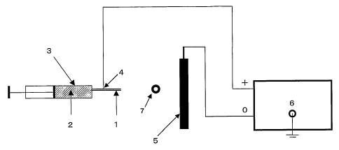
1. nozzle
2. dope
3. dope holding tank
4. positive electrode
5. negative electrode
6. high-voltage generator
CA 02645541 2008-09-05
6
7. winder
8. static electricity removing apparatus
9. winding shaft direction
10. scaffold cut out in direction parallel to
winding shaft direction
il. direction perpendicular to winding direction
12. scaffold cut out in direction perpendicular to
winding shaft
Best Mode for Carrying Out the Invention
The present invention will be described in detail
hereinunder
<scaffold>
The scaffold of the present invention has a 3-D
structure consisting of two end faces and a side face. The
shape of each of the end faces is circular, elliptic,
rectangular, etc. The end faces may be curved with
irregularities. The two end faces may differ in shape and
size. The area of each of the end faces is preferably 0.05
to 8 cm2, more preferably 0.1 to 1 cm2. The side face may
be a continuous curved face or may consist of a plurality
of faces . That is, the shape of the scaf fold of the present
invention is preferably a 3-D structure such as a cylinder
or a polygonal column.
The scaffold of the present invention has a 3-D
structure, that is, expanses in the transverse direction
(x axis), longitudinal direction (y axis) and height
direction (z axis) . In this respect, it differs from plain
nonwoven cloth having expanses in the transverse direction
(x axis) and the longitudinal direction (y axis). In the
scaffold of the present invention, the term "height
direction" refers to a direction perpendicular to one of
the end faces.
The height of the scaffold is preferably 0. 5 mm or more,
CA 02645541 2008-09-05
7
more preferably 2 mm or more. The upper limit of the height
is not limited and it can be said that it depends on a site
where it is used as a prosthetic material. When the height
is smaller than 0.5 mm, the scaffold has low mechanical
strength and is not preferred as a prosthetic material for
a tissue having high mechanical strength such as a knee j oint .
The scaffold of the present invention can be used to grow
a cell on the surface of a prosthetic material by implanting
it in a damaged part of a living body. The scaffold can
be provided in a desired form.
The scaffold of the present invention is composed of
an assembly of fibers. In the present invention, the
expression "aligned in a plane direction" means that the
fibers are aligned substantially parallel to a specific
plane. The fibers may be aligned in any one of the
transverse, longitudinal and oblique directions as long as
they are parallel to this specific plane. The fibers are
aligned substantially parallel to the plane shown by broken
lines in the cylinder denoted by 10 or 12 in Fig. 5. Parts
shown by dotted lines in 10 or 12 of Fig. 5 may form
concentric curves. The direction of the fibers on the plane
is random.
The fibers are preferably aligned in a plane direction
parallel to the height direction as shown by 10 in Fig. 5.
Alternatively, as shown by 12 in Fig. 5, the fibers are
preferably aligned in a plane direction perpendicular to
the height direction.
The diameter of each of the fibers is 0.05 to 50 m.
When the diameter of the fiber is smaller than 0.05 m, the
strength of the scaffold cannot be maintained
disadvantageously. When the diameter of the fiber is
larger than 50 m, the specific surface area of the fiber
becomes small and the number of living cells decreases. The
diameter of the fiber is preferably 0.2 to 50 m, more
CA 02645541 2008-09-05
8
preferably 0.2 to 40 m. The diameter of the fiber can be
obtained by observing the scaffold through, for example,
a scanning electron microscope (about 200 magnifications).
The arbitrary cross section of the fiber may be
substantially spherical or irregular. When the arbitrary
cross section of the fiber is irregular, the specific
surface area of the fiber increases, whereby the area of
the surface of the fiber to which a cell adheres becomes
sufficiently large at the time of culture.
The expression "the arbitrary cross section of the
fiber is irregular" means that the arbitrary cross section
of the fiber has any shape other than a substantially
spherical shape and includes a case where the surface of
the fiber is roughened to have depressions and/or
projections uniformly.
The irregular shape is preferably at least one shape
selected from the group consisting of fine depressions on
the surface of the fiber, fine projections on the surface
of the fiber, depressions formed linearly in the fiber axial
direction on the surface of the fiber, projections formed
linearly in the fiber axial direction on the surface of the
f iber and f ine pores on the surf ace of the f iber. They may
be formed alone or in combination. The above "fine
depressions" and "fine projections" mean that 0.1 to 1 m
depressions and projections are formed on the surface of
the fiber, respectively, and the "fine pores" means that
pores having a diameter of 0.1 to 1 m are existent on the
surface of the fiber. The expression "depressions and/or
projections formed linearly" means that ribs having a width
of 0.1 to 1 m are formed in the fiber axial direction.
The apparent density of the scaffold is 95 to 350 kg/m3,
preferably 100 to 300 kg/m3, more preferably 100 to 250 kg/m3.
When the apparent density is lower than 95 kg/m3, mechanical
strength becomes low though the intrusion of a cell is
CA 02645541 2008-09-05
9
satisfactory. When the apparent density is higher than 350
kg/m3, the intrusion of a cell becomes difficult, which is
not preferred as a scaffold. The apparent density can be
calculated by measuring the volume (area x height) and mass
of the obtained assembly.
When the scaffold is used for implantation, mechanical
strength high enough to withstand weighted compression in
the initial stage of transplantation is required. Shape
stability to compression can be provided by aligning the
fibers of the scaffold of the present invention in the
weighted compression direction. The compressive elastic
modulus of the scaffold of the present invention is
preferably 0.5 to 5 MPa, more preferably 1.5 to 5 MPa.
The porosity of the scaffold of the present invention
is preferably 75 to 90 %, more preferably 78 to 88 %. The
porosity is obtained by subtracting the volume of a polymer
from the volume of a porous material.
The fibers constituting the scaffold of the present
invention are essentially composed of a biocompatible
polymer. Each of the fibers comprises a recurring unit
derived from a biocompatible monomer in an amount of
preferably 80 to 100 mol%, more preferably 90 to 100 mol s
of the total of all the recurring units. Examples of the
biocompatible monomer include glycolic acid, lactic acid,
caprolactones and dioxanones. A blend of biocompatible
polymers may also be used.
The biocompatible polymer is preferably a
bioabsorbable polymer. The bioabsorbable polymer is
preferably essentially composed of an aliphatic polyester.
Examples of the aliphatic polyester include polyglycolic
acid, polylactic acid, polycaprolactone, polydioxanone,
polytrimethylene carbonate, polybutylene succinate,
polyethylene succinate and copolymers thereof. Out of
these, the aliphatic polyester is preferably at least one
CA 02645541 2008-09-05
selected from the group consisting of polyglycolic acid,
polylactic acid, polycaprolactone and copolymers thereof.
A copolymer of lactic acid and glycolic acid is particularly
preferred. The copolymerization ratio of the former to the
5 latter (mol) is preferably 20/80 to 80/20, more preferably
40/60 to 75/25.
Besides the bioabsorbable polymers, biocompatible
polymers such as polyester, nylon, polysulfone,
polyurethane, polyethylene, polypropylene, methyl
10 poly(methacrylate), poly(hydroxyethyl methacrylate),
poly(vinyl chloride) and polysiloxane may be used as the
polymer constituting the porous material.
The intrinsic viscosity of the biocompatible polymer
is 0.1 to 1.4 dL/g, preferably 0.04 to 1.3 dL/g, more
preferably 0.6 to 1.2 dL/g (30 C, hexafluoroisopropanol).
The scaffold of the present invention may further
contain a second component except the biocompatible polymer.
The component is preferably at least one selected from the
group consisting of cell growth factors such as
phospholipids, carbohydrates, glycolipids, steroids,
polyamino acids, proteins, polyoxyalkylenes, FGF (fiber
blast cell growth factors) , EGF (epidermal growth factors) ,
PDGF (platelet-derived growth factors), TGF-(3 ((3 type
transforming growth factors), NGF (nerve growth factors),
HGF (hepatic cell growth factors) and BMP (bone
morphogenetic factors). Specific examples of the second
component include phospolipids such as phosphatidylcholine,
phosphatidylethanolamine, phosphatidylserine and
phosphatidylglycerol, and/or carbohydrates such as
polygalacturonic acid, heparin, chondroitin sulfate,
hyaluronic acid, dermatan sulfate, chondroitin, dextran
sulfate, sulfated cellulose, alginic acid, dextran,
carboxymethyl chitin, galactomannann, gum Arabic, traganth
gum, gellan gum, sulfated gellan, karaya gum, carrageenan,
CA 02645541 2008-09-05
11
agar, xanthan gum, curdlan, pullulan, cellulose, starch,
carboxymethyl cellulose, methyl cellulose, glucomannan,
chitin, chitosan, xyloglucan and lenthinan, and/or
glucolipids such as galactocerebroside, glucocerebroside,
globoside, lactosylceramide, trihexosylceramide,
paragloboside, galactosyldiacylglycerol,
sulfoquinobosyldiacylglycerol, phosphatidylinositol and
glycosylpolyprenol phosphate, and/or steroids such as
cholesterols, cholic acid, sapogenin and digitoxin, and/or
polyamino acids such as polyaspartic acid, polyglutamic
acid and polylysine, and/or proteins such as collagens,
gelatin, fibronectin, fibrin, laminin, casein, keratin,
sericin and thrombin, and/or polyoxyalkylenes such as
polyoxyethylene alkyl ether, polyoxyethylene propylene
alkyl ether, polyoxyethylene sorbitan ether. The
preferred content of the second component is 0. 01 to 50 parts
by weight based on 100 parts by weight of the biocompatible
polymer.
<manufacturing process>
The scaffold of the present invention can be
manufactured through first to third steps.
( f irst step)
The first step is a so-called"electrospinning method".
The first step is to form fibers by delivering a dope
containing a biocompatible polymer into an electrostatic
field formed between electrodes from a nozzle.
The electrostatic field is formed between a pair of
electrodes or among a plurality of electrodes. The
electrodes may be made of a metal, inorganic or organic
material as long as they show conductivity. Also they may
have a conductive metal, inorganic or organic thin film on
an insulating material. High voltage may be applied to any
one of the above electrodes. The present invention
CA 02645541 2008-09-05
12
includes a case where two high-voltage electrodes which
differ from each other in voltage value (for example, 15
kV and 10 kV) and one electrode connected to an earth are
used and a case where more than 3 electrodes are used.
Preferably, one of the electrodes is a nozzle and the other
electrode is a collection electrode.
The distance between the electrodes which depends on
the amount of charge, the size of the nozzle, the flow rate
of a spinning liquid and the concentration of the spinning
liquid is suitably 5 to 20 cm at 10 kV. The potential of
static electricity to be applied is preferably 3 to 100 kV,
more preferably 5 to 50 kV, much more preferably 5 to 30
kV.
The dope contains a biocompatible polymer and a solvent.
The biocompatible polymer has already been described above.
The content of the biocompatible polymer in the dope is
preferably 1 to 30 wt%, more preferably 2 to 20 wt%. When
the content of the biocompatible polymer is lower than 1
wt%, it is difficult to form fibers disadvantageously.
When the content is higher than 30 wta, the diameter of the
obtained fibers becomes too large disadvantageously.
The solvent is preferably a substance which dissolves
the biocompatible polymer, has a boiling point of 200 C or
lower at normal pressure and is liquid at room temperature.
Examples of the solvent include methylene chloride,
chloroform, acetone, methanol, ethanol, propanol,
isopropanol, toluene, tetrahydrofuran,
1,1,1,3,3,3-hexafluoroisopropanol, water, 1,4-dioxane,
carbon tetrachloride, cyclohexane, cyclohexanone,
N,N-dimethylformamide and acetonitrile. Out of these,
methylene chloride, chloroform and acetone are
particularly preferred from the viewpoints of the
solubility of a biocompatible polymer, especially an
aliphatic polyester. These solvents may be used alone or
CA 02645541 2008-09-05
13
in combination. in the present invention, another solvent
may be used in limits not prejudicial to the object of the
present invention.
The diameter of the nozzle is preferably 0.6 to 1.5
mm. When the dope is supplied into the electrostatic field
from the nozzle, a plurality of nozzles may be used to
increase the production rate of a fibrous material.
Delivery may be carried out by extruding the dope with
a syringe having a piston like an injector. A tube having
a nozzle at the end may also be used. In this case, the
dope is drawn by the potential difference of static
electricity to be spun toward the electrode. The fibers
may be in a state that the solvent is distilled off or in
a state that the solvent is still contained.
A static electricity removing apparatus is preferably
used between the nozzle and the electrode. The static
electricity removing apparatus is an apparatus which
applies an ion air to the fibers to keep ion balance uniform
and disperses the fibers into air by easing the charged state
of the fibers before they reaches the electrode. The
thickness of a roll can be increased by using this apparatus.
A scaffold having a large diameter can be obtained by
increasing the thickness of the roll.
(second step)
The second step is to wind up the obtained fibers on
a rotary winding shaft and accumulate them so as to obtain
a roll in which the fibers are aligned in a plane parallel
to the winding shaft.
The fibers are accumulated around the winding shaft
of a winder between the nozzle and the collection electrode.
The shape of the winding shaft may be columnar or prismatic.
Since the average apparent density of the scaffold
depends on the revolution of the winding shaft, a scaffold
CA 02645541 2008-09-05
14
having a desired average apparent density can be obtained
by controlling the revolution of the winding shaft. Stated
more specifically, when the revolution is high, the average
apparent density of the obtained scaffold is high. When
the revolution is low, the average apparent density of the
obtained scaffold is low. The revolution of the winding
shaft is preferably 1 to 1,000 rpm, more preferably 5 to
200 rpm.
The obtained roll is substantially aligned in a plane
parallel to the winding shaft. The shape of the roll is
arbitrary such as columnar or spindle-like.
After the second step, the obtained roll is preferably
heated. The heating temperature is preferably 40 to 90 C.
By heating, the fibers are thermally fused to one another,
thereby making it possible to obtain a scaffold having
excellent compressive strength.
The first step and the second step will be explained
with reference to Figs. 1 to 4. Fig. 1 shows an example
using a syringe and Fig. 2 shows an example using a tubular
discharger. In Fig. 1, the dope (2) is charged into the
dope holding tank (3) of a syringe having a nozzle (1).
Voltage is applied to the nozzle (1) by a high voltage
generator (6) and an electrostatic field is formed between
a positive electrode (4) and a negative electrode (5) . When
the dope (2) is extruded from the nozzle (1), the charged
dope is moved toward the negative electrode (5) through the
electrostatic field to form fibers.
The fibers can be formed by the method shown in Fig.
2. The dope (2) is charged into the dope holder tank (3)
of a tubular discharger having a nozzle (1). A positive
electrode (4) is inserted into the dope holding tank (3)
and voltage is applied to the nozzle by the high-voltage
generator (6) to form an electrostatic field between the
positive electrode (4) and the negative electrode (5) . The
CA 02645541 2008-09-05
charged dope is discharged from the nozzle (1) by adjusting
the distance between the nozzle (1) at the end of the
discharger and the negative electrode (5) and moved toward
the negative electrode (5) through the electrostatic field
5 to form f ibers . The fibers are wound up by the winder (7)
before the negative electrode (5).
In the present invention, while the dope (2) is spun
toward the negative electrode (5), the solvent is evaporated
and the fibers are formed. Although the solvent evaporates
10 completely at normal room temperature while the fibers are
collected to the winder (7), if the evaporation of the
solvent is incomplete, the dope may be spun under reduced
pressure. The spinning temperature depends on the
evaporation behavior of the solvent and the viscosity of
15 a spinning liquid but is generally 0 to 50 C.
Fig. 3 and Fig. 4 show examples in which a static
electricity removing apparatus (8) is installed. The
static electricity removing apparatus (8) is installed
between the nozzle (1) and the negative electrode (5) to
carry out spinning so that the fibers can be collected to
the winder (7).
(third step)
The third step is to cut out a 3-D structure from the
obtained roll. The 3-D structure can be bored out by using
a cylindrical borer as shown in Fig. 5. In Fig. 5, the 3-D
structure is preferably bored out (10) such that the height
direction of the 3-D structure becomes parallel to the
aligning direction of the fibers. Also, the 3-D structure
is preferably bored out (12) such that the height direction
of the 3-D structure becomes perpendicular to the aligning
direction of the f ibers . The scaffold (10) is superior in
compressive strength to the scaffold (12).
CA 02645541 2008-09-05
16
<differentiation and growth of cell>
A cell can be differentiated and grown by using the
scaffold of the present invention. The differentiation and
growth of a cell may be carried out in vitro or in vivo.
In vitro, the scaffold may be used as a culture medium for
differentiating and growing a cell. In vivo, the scaffold
of the present invention may be used as a prosthetic material.
Particularly, a living tissue can be regenerated by burying
the scaffold of the present invention in a damaged affected
part. Alternatively, the scaffold of the present invention
having a cultured cell in vitro may be buried in an af f ected
part as a prosthetic material. The living tissue is, for
example, an osteochondral tissue.
Examples
Materials and measuring methods used in Examples are
given below.
(1) Lactic acid-glycolic acid copolymer; LACTEL (DL lactic
acid/glycolic acid copolymer, molar ratio = 50/50,
intrinsic viscosity: 1.05 dL/g, 30 C,
hexafluoroisopropanol, manufactured by Absorbable
Polymers International Co., Ltd.)
(2) Methylene chloride, ethanol, formaldehyde;
manufactured by Wako Pure Chemical Industries, Ltd.
(3) Rat mesenchymal stem cell; manufactured by Dainippon
Sumitomo Pharmaceuticals, Ltd.
(4) MEM (Minimum Essential Medium), FBS(Fetal Bovine
Serum), PBS (Phosphate-buffered Saline),
antibiotic-antimycotic, 0.05 % Trypsin-EDTA solution;
manufactured by Invitrogen Co., Ltd.
(5) L-ascorbic acid 2-phosphate magnesium salts n-hydrate
(water content of 26.7 %), (3-glycerophosphate disodium
n-hydrate, Dexamethason, Triton X-100, Toluidine Blue;
manufactured by Sigma Co., Ltd.
CA 02645541 2008-09-05
17
(6) Pico Green (registered trademark) ds DNA Quantitation
Kit; manufactured by Molecular Probe Co., Ltd.
<Example 1>
(preparation of dope)
A lactic acid-glycolic acid copolymer (molar ratio=
50/50) was dissolved in a mixed solvent of methylene
chloride and ethanol to prepare a 15 wt% dope.
(spinning)
A cylindrical roll composed of an assembly of fibers
was obtained by the electrospinning method using the
apparatus shown in Fig. 4. The inner diameter of the nozzle
(1) was 1.3 mm. The distance from the nozzle (1) to the
winder (7) was 20 cm, and the distance from the nozzle (1)
to the static electricity removing apparatus (8) was 35 cm.
Applied voltage was 15 kV. The winder (7) and the static
electricity removing apparatus (8) manufactured by Kasuga
Denki Co., Ltd. were installed between the nozzle (1) and
the negative electrode (5) . The positive electrode (4) was
inserted into the dope holding tank (3). The revolution
of the winder (7) was set to 100 rpm.
The dope was fed to the dope holding tank (3), the
distance between the nozzle (1) and the negative electrode
(5) was adjusted, and fibers were delivered from the nozzle
(1) . Delivery was continued for 120 minutes, and the fibers
were wound up by the rotating winder (7) to obtain a
cylindrical roll. The roll was put into a thermostatic
device and heated at 80 C for 10 minutes.
(cutting out)
A cylindrical scaffold having a diameter of 5 mm and
a height of 5 mm denoted by 10 in Fig. 5 was cut out from
the obtained roll by using a biopsy trepan (manufactured
CA 02645541 2008-09-05
18
by Kai Industries, Ltd.) as shown in Fig. 5.
(evaluation of characteristic properties)
The characteristic properties of the obtained scaffold
were measured by the following methods. The results are
shown in Table 1.
(1) diameter of fiber
The diameter of each fiber was observed visually
through a digital microscope (VHX Digital Microscope of
Keyence Co., Ltd.) or a scanning electron microscope
(manufactured by JEOL Ltd., 200 magnifications).
Arbitrary 10 fibers were selected from each view field in
electron microscopic observation and measured, and this
operation was carried out for 5 view fields to calculate
the average value of 50 fibers. Massive foreign matter or
a bundle of fibers fused to one another produced in the step
of forming fibers were not measured.
(2) apparent density of scaffold
The apparent density of the scaffold was calculated
from the following equation.
p = 4m/7Ed2h
(p: apparent density of porous material, m: mass, d:
diameter, h: height)
(3) porosity of scaffold
The porosity of the scaffold was calculated from the
following equation.
s = 1 - P/Po
(s: porosity of scaffold, p: apparent density of porous
material, po: intrinsic density of polymer)
(4) compressive strength
The compressive strength of the scaffold corresponding
CA 02645541 2008-09-05
19
to (10) in Fig. 5 was measured in accordance with JISK 7220.
That is, the scaffold in which fibers were aligned parallel
to the height direction of the cylinder was measured. A
test specimen was placed between the pressure planes of a
material tester, the center line of the specimen was aligned
with the center lines of the pressure planes, and it was
confirmed that the upper and lower surfaces of the specimen
were parallel to the pressure planes. A load was applied
to the test specimen at a constant test speed of 10 mm/min
to measure compressive strength until a compression limit
was reached.
<Example 2>
(preparation of dope)
The same lactic acid-glycolic acid copolymer as in
Example 1 was used to prepare a 10 wt% dope.
(spinning)
A cylindrical roll composed of an assembly of fibers
was obtained in the same manner as in Example 1 except that
the delivery time was set to 90 minutes and the heat
treatment was carried out at 70 C for 10 minutes.
(cutting out)
A cylindrical scaffold having a diameter of 5 mm and
a height of 5 mm corresponding to 10 in Fig. 5 was cut out
from the obtained roll in the same manner as in Example 1.
Fig. 6 (top end face) and Fig. 7 (bottom end face) show
microphotographs (15 magnifications) of a section parallel
to the end faces of the scaffold corresponding to 10 in Fig.
5. It is seen that the fibers were accumulated in layers.
(evaluation of characteristic properties)
The characteristics properties of the scaffold were
CA 02645541 2008-09-05
evaluated in the same manner as in Example 1. The results
are shown in Table 1.
(biological evaluation of scaffold)
5 (preparation of cell)
The biological evaluation of the scaffold was carried
out by the following method. The mesenchymal stem cell of
a rat was cultured in MEM containing 15 % of FBS and 1 %
of antibiotic-antimycotic at 37 C in a 5 CO2 atmosphere
10 for 3 passages.
(sowing and culture of cell)
The prepared rat mesenchymal stem cells were seeded
in the obtained scaffold at a density of 6.0 x 10⁶/cm3 and
15 cultured in MEM containing 15 % of FBS, 1 % of
antibiotic-antimycotic, 10 M of dexamethasone, 50 M of
L-ascorbic acid 2-phosphate magnesium salts n-hydrate and
10 mM of (3-glycerophosphate disodium n-hydrate at 37 C in
a 5% COz incubator for 12 days. The culture medium was
20 exchanged 3 times a week.
(evaluation)
The scaffold was taken out on the first day, sixth day
and 12-th day of culture to measure the amount of DNA and
evaluate it histologically.
(1) Amount of DNA
The amount of DNA was measured based on the measurement
manual of Pico Green (registered trademark) ds DNA
Quantitation Kit. The sample to be measured was frozen and
molten with 0. 2 % of Triton-Xl00 three times and ground with
supersonic waves to obtain a cell suspension, and an extract
was prepared from the suspension. 100 l of the measured
sample treated with enzyme was put into a micro-plate with
CA 02645541 2008-09-05
21
96 holes, and 100 l of Pico Green (registered trademark)
ds DNA Quantitation Reagent diluted with TE (pH of 7.5) 200
times was added to the sample to measure the amount of DNA
with 485 nm excitation light and 535 nm fluorescence. A
calibration curve was drawn from the value of a standard
DNA solution and the amount of DNA of the measurement sample
was calculated based on the curve. The result is shown in
Table 2. The amount of DNA is proportional to the number
of grown cells.
(2) Histological evaluation
For histological evaluation, the scaffold was immersed
in 10 % of formaldehyde before sampling. Before it was
stained, it was cleaned with distilled water, immersed in
100 % of ethanol for 1 hour twice, 90 % of ethanol for 1
hour and 70 % of ethanol for 1 hour to be cleaned while it
was diluted stepwise. The obtained scaffold was immersed
in distilled water for 15 minutes to be cleaned and then
in a 0.4 % toluidine blue-aqueous solution for 1 minute.
Thereafter, it was cleaned in running water for 1 minute
to remove excess of a staining solution and observed through
a digital microscope at 450 magnifications.
(3) Result
The measurement result of the amount of DNA is shown
in Table 2. Fig. 8 and Fig. 9 show photomicrographs of the
stained scaffold on the lst and 12-th days of culture. It
is seen that the scaffold on the 12-th day of culture has
higher staining density than the scaffold on the lst day,
the stained area reaches a deep portion of the scaffold,
and the growth of the cell and the production of a cartilage
matrix proceed well.
<Example 3>
CA 02645541 2008-09-05
22
(manufacture of scaffold)
The operation of Example 2 was repeated to obtain a
cylindrical scaffold having a diameter of 5 mm and a height
of 5 mm corresponding to 12 in Fig. 5. The measurement
results of the characteristic properties of the scaffold
are shown in Table 1.
Fig. 10 shows a photomicrograph (200 magnifications)
of a section perpendicular to the end surface of the scaf fold
corresponding to 12 in Fig. 5. It is seen that the fibers
are aligned in a plane direction. Fig. 11 (top end surface)
and Fig. 12 (bottom end surface) show photomicrographs (15
magnifications) of a section parallel to the end faces of
the scaffold corresponding to (12) in Fig. 5. It is seen
that the fibers are accumulated densely like the mesh of
a net.
(biological evaluation)
A cell was cultured in the same manner as in Example
2 except that the obtained scaffold was used to measure the
amount of DNA. The result is shown in Table 2. Fig. 13 and
Fig. 14 show photomicrographs of the stained scaffold on
the lst and 12-th days of culture. It is seen that the
scaffold on the 12-th day of culture has higher staining
density than the scaffold on the ist day, the stained area
reaches a deep portion from the surface of the scaffold,
and the growth of a cell and the production of a cartilage
matrix proceed well like Example 2.
CA 02645541 2008-09-05
23
4-3
Li+
~ oe f!1 ~ d1 N ~
O~~ a 01 e-i 0
~4 rl ri 41E O O 0
+) a
N El' EO
-r-,
a~ b
EO >
Ul .r-i U U1
UO 1~ r~l (d r-1 00 ~M ~
~ ~ ~ 4 ~o Ln ri 0
U N d' ~ r-i U ~ N E v r44
d r~
0
tUA N m w r
00 0 ao
>,, v ~ o ~ o
41
-rl in r- o z
Ef)p th M N
~j O OD OC)
O y.i
a 0
4-j ~~. 0
4J
~ -~ 5 o ~r d~
(d N N N N
~a,x
a) r-I m N Ol
Ol O O
rd rd ~
[- (d O r- rl
~-I ~-I
a, d, _ U W
N-~ ~
~ w ~ ~ ~
=,-I 4.4
A O
a)
. 4J 41
U 4-) ~ r-A
'O ~ '~ N 0 0 0 U
a..) H~ ri I U U
''i 41
o 44 4-I O O
OU b >, fd rd
0 ro b
.,~
4-3 4-3
0 0 0
Q ~
.H r Q r-1 rl H r i ~D N
04 cn 0
a -~
~
ri N f7
O
U) N N
N
r-i ~4
~ ~ ~ ..
W W W *
CA 02645541 2008-09-05
24
Effect of the Invention
The scaffold of the present invention has such high
mechanical strength that it can withstand weighted
compression in the initial stage of transplantation.
Therefore, it can be used in a site which requires mechanical
properties, such as a cartilage damaged part. Since the
scaffold of the present invention is composed of a
biocompatible polymer, it has no bad influence upon a living
body. The scaffold of the present invention has a certain
fiber density, facilitates the intrusion of a cell and
enables the supply of oxygen and nutrition and the discharge
of carbon dioxide and waste matter to be carried out swiftly.
Therefore, the scaffold can grow a cell well.
According to the manufacturing process of the present
invention, the scaffold can be manufactured easily.
According to the manufacturing process of the present
invention, as fibers obtained by the electrospinning method
are accumulated on a rotary shaft , accumulated f ibers having
a uniform accumulation density in the accumulation
direction are obtained. Accumulated fibers uniform in a
plane parallel to the winding shaft are obtained. Further,
certain tension is applied to the fibers by winding up the
fibers on the rotary winding shaft, thereby making it
possible to obtain high-density accumulated fibers.
According to the cell growing method of the present
invention, a cell can be grown well. According to the
living tissue regeneration method of the present invention,
a damaged living tissue can be regenerated well.
Industrial Applicability
The scaffold of the present invention is useful as a
cell culture medium in the field of regeneration medicine.
The scaffold of the present invention is useful as a
prosthetic material, especially a prosthetic material for
CA 02645541 2008-09-05
a site in which mechanical properties are important, such
as an osteochondral damaged part.