Note: Descriptions are shown in the official language in which they were submitted.
CA 02645814 2008-09-12
WO 2007/110991 PCT/JP2006/321453
1
DESCRIPTION
VAPOR COMPRESSION REFRIGERATING CYCLE, CONTROL METHOD THEREOF,
AND REFRIGERATING APPARATUS TO TivHICH THE CYCLE AND THE CONTROL
METHOD ARE APPLIED
Technical Fie1d
The present invention'relates to a vapor compression
refrigerating cycle applied to a refrigerator and air
conditioner, control methods thereof, and a refrigerating
apparatus to which the cycle and control methods are applied.
Background Art
A system of typical vapor compression refrigerating cycle
is composed as shown schematically in FIG. 13. The cycle ia shown
in FIG.14 as a T-S, diagram with temperature as the ordinate
and entropy as the abscissa, in which the cycle operates the
process a-b'-c-d"-a.
That is, saturated vapor of a refrigerant at point a is
compressed adiabatically to point b' by a compresso.r 02, then
cooled from point b to point a under constant.pressure in a
condenser 04 to be condensed to saturated liquid at point c
while heat quantity of Q1=being deprived of the refrigerant.
The saturated liquid is expanded through an expansion means
(expansion valve) 06 to be decreased in pressure from P2 to
P1 through an isenthalpic expansion process c-d". The
refrigerant is in a state of wet vapor at point d", i.e. a
mixture of saturated liquid of state point c and saturated vapor
of state point a. The saturated liquid in the wet vapor
evaporates in an evaporator 08 under pressure P1 and absorbs
heat quantity of Q2 from specified substance, thus
refrigeration is effected.
A vapor compression refrigerating cycle like this can be
considered as a cycle based on the reversed Carnot cycle.
FIG.16 shows the Carnot cycle on a T-S diagram. When the
Carnot cycle is operated in a reversed direction, i.e. in a
CA 02645814 2008-09-12
WO 2007/110991 PCT/JP2006/321453
2
direction shown by arrows to operate the process of a-b-c-d,
a refrigerating cycle is effected. In' FIG. 16, the process a-b
is adiabatic compression, process b-c is isothermal
compression, process c-d is adiabatic expansion, and process
d-a is isothermal expansion.
Applying the reversed Carnot cycle of FIG.16 to the T-S
diagram of the vapor compression refrigerating cycle of FIG. 14,
each of processes a-b, b-c, c-d, 'and d-a in FIG.14 can be
considered to correspond to each of processes represented by
the same symbols in the reversed Carnot cycle of FIG.16. That
means that the vapor compression refrigerating cycle can'be
considered as a cycle for operating the below the line of
,saturati:on (saturated liquid line 1-1' and dry saturated vapor
line m-m' , both lines c6incide at the critical point not shown
in the drawing).In FIG.14, a-b is adiabatic compression
process, b-g is isothermal compression process,. g-c is
isothermal condensation process, c-d is adiabatic expansion
process, and d-a is isothermal evaporation process.
The feature of the reversed Carnot cycle a-b-c-d-a in FIG. 14
can be considered schematically that the isothermal
compression process b-c,and isothermal expansion process d-a
of the Carnot cycle are replaced by the condensation process
g-c and evaporation process d-a by allowing a large part of
the cycle to operate below the line of saturation with only
the process b-g belonging to a part of. isothermal coinpression
process of the Carnot cycle.
As isothermal compression process is difficult to realize,
the process b-g outside the dry saturated vapor line is replaced
by the adiabatic compression process b-b' and isobaric cooling
process b'-g in the actual vapor compression refrigerating
cycle.
Also, as isentropic expansion process c-d is difficult to
realize in adiabatic expansion of 2-phase refrigerant
consisting of vapor and liquid refrigerant in the actual vapor
compression refrigerating cycle, isenthalpic expansion
process c-d" is substituted for the isentropic expansion
CA 02645814 2008-09-12
WO 2007/110991 - PCT/JP2006/321453
3
process c-d by use of an expansion,valve in the actual vapor
compression refrigerating cycle.
FIG.15 is a P-H diagram (pressure-enthalpy diagram) for T-S
diagram of FIG.14.
As has been explained, the typical vapor compression
refrigeratirig cycle can be considered a practical cycle based
on the reversed Carnot.cycle.
More specifically, as mentioned above, the feature of the
vapor compression refrigerating cycle can.be considered a
cycle intended for putting the Carnot cycle'to practical use,
in which a large part of the isothermal compression process
of the'reversed Carnot cycle a-b-c-d-a of FIG.16 is replaced
by the isothermal condensation process g-c by utilizing the
characteristic of wet v'apor'below the line of saturation, the
remainder, i.e. the process b-g, is replaced by the adiabatic
compression process b-b' and isobaric process b'-g,.further
the isentropic expansion process is replaced by the
isenthalpic expansion process which is realized by use of an
expansion valve, and,the isothermal expansion process by the.
isothermal evaporation process.
By the way, there is knowri the Stirling cycle and Ericsson
cycle as reversible cycles inaddition to the Carnot cycle.
FIG.17 is a T-S diagram of the reversed Stirling cycle, in
which process a-b is isometric heat absorption, process b-c
is isothermal compression, process c-d is isometric heat
dissipation, and process d-a is isothermal expansion. The
amount of heat absorbed in the isometric heat absorption
process a-b is equal to that dissipated in the isometric heat
dissipation process c-d, the heat exchange being done through
the intermediary of a regenerating heat exchanger.
FIG.18 is a T-S diagram of the reversed Ericsson cycle, in
which process a-b is isobaric heat absorption, process b-c is
isothermal compression, process c-d is isobaric heat
dissipation, and process d-a is isothermal expansion. The
amount of heat absorbed in the isobaric heat absorption process
a-b is equal to that dissipated in the isobaric heat dissipation
CA 02645814 2008-09-12
WO 2007/110991 PCT/JP2006/321453
4
process c-d, the heat exchange 'being done through the
intermediary of a regenerating heat'exchanger.
There are many proposals of refrigerators using the typical
vapor compression refrigerating cycle such as disclosed for
example in Japanese Laid-Open Patent Application
No.2004-108617, No.2002-156161. In Japanese Laid-Open Patent
Application No.55-60158 is recited the theoretical
coefficient of performance when consideringthe vapor
compression refrigerating cycle as -.the reversed Carnot
cycle ( see page 2, the middle part of upper right column of the
official gazette), thus it is, known to evaluate the vapor
compression refrigerating cycle presuming the reversed Carnot
cycle of the, vapor'compression refrigerating cycle.
Disalosure of the Invention
As to the improvement of efficiency of the conventional vapor
compression refrigerating cycle, there have been many
proposals as has been disclosed in patent literatures
mentioned above. However, further improvement of efficiency is desired.
The object of the present invention is to provide a vapor
compression refrigerating cycle, control methods thereof, and
a refrigerating apparatus adopting the -method, with which
operation efficiency exceeding the conventional vapor
compression refrigerating cycle can be attained, by modifying
the basic cycle of vapor compression refrigerating cycle, that ,
is, by modifying the basic cycle of vapor compression
refrigerating cycle from the reversed Carnot cycle to the
reversed Ericsson cycle.
To attain the object, the present invention proposes a vapor
compression refrigerating cycle comprising a compressor, a
condenser, a regeneration heat exchanger, an expansion means,
and an evaporator connected in series, wherein said cycle is
based on a cycle corresponding to a reversed Ericsson cycle
in which isothermal heat dissipation process and isothermal
heat absorption process occur overstriding a saturated vapor
CA 02645814 2008-09-12
WO 2007/110991 PCT/JP2006/321453
line and saturated liquid line respectively and heat exchange
is carried.out between isobaric heat'dissipation process in
a liquid zone and.isobaric heat absorption process in a
superheated vapor zone, and wherein a process part occurring
in a superheated vapor zone of said isothermal heat dissipation
process in said,reversed Ericsson cycle (an isothermal
compression process) is. substituted by adiabatic compression
process and isobaric heat dissipation process, said adiabatic
compression being carried out by said' compressor and said
isobaric heat dissipation being carried out in said condenser
together with remaining process part occurring in said
superheated vapor zone of said isothermal heat dissipation
process under isothermal and isobaric condition, a part of said
isobaric heat dissipation process in the liquid zone is carried
out in said regeneration heat exchanger by releasing heat from
refrigerant liquid in the liquid zone to refrigerant vapor
entering said compressor, remaining process part of said
isobaric heat dissipation process in the liquid zone is
substituted by isenthalpic or isentropic expansion, the
expansion being.carried out by said expansion means, and
expanded refrigerant is introduced to said evaporator to carry
out isothermal and isobaric heat absorption and then to be
sucked into said compressor.
Said=reversed Ericsson cycle as shown in a T-S diagram of
FIG.1 by process of a-b-g-c-d-a is called here a theoretical
vapor compression Ericsson cycle.
According to the invention, a vapor compression
refrigerating cycle of a-b-b'-g-c-d'-e'-a or
a-b-b' -g-c-d' -e" -a shown in a T-S diagram of FIG. 1 by modifying
said reversed Ericsson cycle, i.e. theoretical vapor
compression Ericsson cycle, performed overstriding a
saturated vapor line and saturated liquid line such that
reversible isothermal compression process b-g is substituted
by adiabatic compression process b-b' and isobaric heat
dissipation process b'-g, and a part of reversible isobaric
heat dissipation process c-d is substituted by isenthalpic or
CA 02645814 2008-09-12
WO 2007/110991 PCT/JP2006/321453
6
isentropic expansion respectively:
FIG.2 is a P-H diagram corresponding to the T-S diagram of
FIG.1. Cycle a-b-g-c-d-a shown in FIG.1 and FIG.2 is defined
here as a theoretical vapor compression Ericsson cycle. This
reversed Ericsson cycle a-b-g-c-d-a operates overstriding the
dry saturated vapor line mm' and saturated liquid line 11'.
Process a-b is reversible isobaric heat absorption, process
b-g-c is.isothermal compression, process c-d is reversible
isobaric heat dissipation, and process d-a is isothermal
expansion. The reversible isobaric process c-d is operated~in
the liquid zone outside the saturated liquid line, the
reversible isobaric heat absorption.a-b is operated in, the
vapor zone outside the dry saturated vapor line, a large part
of the isothermal compression b-g-c (high-pressure side
isothermal process) consists of condensation process, and a
large part of the isothermal process d-a .consists of
evaporation process.
The isothermal process b-c of said reversed Ericsson cycle
(theoretical vapor compression Ericsson cycle) consists of a
partial process.b-g and a partial process g.=c, the partial
process b-g being isothermal compression process and, the
partial.process g-c is isothermal condensation process.
In FIG.1, in order that the reversed Ericsson cycle is
effected by the cycle a-b-g-c=d-a, the heat amount absorbed
in the reversible heat absorption process.a-b and'the heat
amount dissipated in the isobaric heat dissipation process c-d
must be equal. However, these heat amounts are not equal in
general with a usual refrigerant, because the heat absorption
is effected in a vapor phase and heat dissipation is effected
in a liquid phase and physical properties (such as specific
heat) differ resulting in unequal specific enthalpy difference
between both the processes. Therefore, temperature difference
arises between liquid side average temperature and vapor side
average temperature in the regeneration heat exchanger in
which heat exchange is performed between reversible isobaric
heat absorption process a-b and reversible isobaric heat
CA 02645814 2008-09-12
WO 2007/110991 PCT/JP2006/321453
7
dissipation process c-d, and reversible heat exchange is
impossible.
When d' is a point on the line c-d, at which state point
the specific en.thalpy difference between the point d''and c
is equal to that between the point a and b, and if isenthalpic
expansion d"-e" is performed,,a cycle a-b-g-c d'-e"-a is an
irreversible cycle.
FIG.3 is-a graph showing liquid side temperature changes
and vapor side temperature changes in-the regeneration heat
exchanger. As shown in the graph, even. in the case high
.temperature side liquid refrigerant temperature and low
temperature side vapor refrigerant temperature coincide with
each other at, the high temperature side end and low temperature
side end respectively 'of the regeneration heat exchanger,
temperature difference A TB arises between the high
temperature side liquid refrigerant and low temperature side
vapor refrigerant inside the heat exchanger, so irreversible
heat exchange can not be evaded in the regeneration heat
exchanger. ,
However, it is theoretically possible~ to allow the
temperature difference between the liquid refrigerant and
vapor refrigerant at the high-temperature side end and low
temperature side end respectively of the re'generation heat
exchanger to be zero as shown in FIG. 3, and when this is realized
the cycle is defined here as a vapor compression Ericsson cycle.
Temperature difference. between liquid refrigerant vapor
refrigerant at the low temperature side end and high
temperature side end respectively of the regeneration heat
exchanger can be reduced to zero by widening the isobaric heat
absorption process a-b to f-a-b so that vapor side specific
enthalpy difference is equal to liquid side specific enthalpy
diff erence .
This is possible by controlling so that the state of
refrigerant at the vapor side inlet is shifted from the sate
point a to a state point f in the wet vapor zone.
The reason why refrigerating capacity of the vapor
CA 02645814 2008-09-12
WO 2007/110991 PCT/JP2006/321453
8
compression refrigerating cycle of the invention is increased
compared with the typical conventibnal vapor compression
refrigerating cycle. with the same refrigerant flow will be
explained hereunder.
The refrigerating capacity of the typical vapor compression
refrigerating based on the reversed Carnot cycle is 4Hac as
shown in FIG.14, and that of the vapor compression
refrigera.ting cycle of the invention is 4Had' as shown in FIG. 1
and FIG.2. As OHad' =.4Hac+AHba, in the reversed Ericsson cycle
of the invention, refrigerating capacity always increases by
AHba compared with that of the conventional cycle even when the
state of refrigerant a the vapor side inlet of therefrigerating
heat exchange varies between. a section a-f. That is,
refrigerant capacity' increases by the heat amount
corresponding the heat amount which the vapor sucked into the
compressor is heated.in the, regeneration heat exchanger when
mass flow of refrigerant is the same.
Said increase of refrigerating capacity will be explained
using enthalpies at each of the state points and relations
between the enthalpies.
In FIG. 1, heat exchange is carried out between refrigerant
in vapor phase in isobaric heat absorption process a-b and that
in liquid phase in isobaric heat dissipatiori process c-d in
the regeneration heat exchanger. Since difference of enthalpy
of the process a-b is not-equal to that of the process c-d,
a state point d' is determined in the process c-d so that the
following equation (1) is sufficed.
Hb-Ha=Hc-Hd' (1)
Similarly, state point f is determined on the evaporation
line Y in Fig. 2 by the following equation (2) so that a heat
amount same to the heat amount dissipated in the process c-d
is exchanged in process f-b.
Hb-Hf=Hc-Hd (2)
The equation (2) means that the state of refrigerant at the
vapor side inlet of the regeneration heat exchanger is shifted
from point a at which refrigerant vapor is in a state of
CA 02645814 2008-09-12
WO 2007/110991 PCT/JP2006/321453
9
saturated vapor to point f at which refrigerant vapor is in
a state of wet vapor in order to alldw the reversed Ericsson,
cycle a-b-g-c-d-a to be performed.
When refrigerant at the vapor side inlet of the regeneration
heat exchanger is saturated vapor as shown by point a in FIG.
1 and 2, refrigerant capacity is given by the following equation
(3).
q)a=Ha-Hd' (3)
On the other hand, when refrigerant at the vapor side inlet
of the regeneration heat exchanger is wet vapor as shown'by
point f in FIG. 1 and 2, refrigerant capacity 'is given by the
following equation (4).
(D f=Hf-Hd (4)
Refrigerating capacity' of the conventional vapor
compression refrigerating cycle based on the reversed Carnot
cycle is given by the following equation (5).
(Dc=Ha-Hc (5)
Difference dq) in refrigerating capacity of the cycle of the
invention and that of the conventional cycle can be obtained
from equations ( 2)-( 5) and given by the following equations (6)
and (7).
When refrigerant at the vapor side inlet of the regeneration
heat exchanger is saturated vapor as shown by point a,
dq)a=(Da-(Dc =(Ha-Hd' )-(Ha-Hc)=Hc-Hd'=Hb-Ha (6)
and when refrigerant at the vapor side inlet of the regeneration
heat exchanger is saturated vapor as shown by point f,
(Df=q)f-(Dc =(Hf-Hd)-(Ha-Hd)=(Hc-Hd)-(Ha-Hf)=Hb-Ha
(7)
It is recognized from equations (6) and (7) that
refrigerating capacity is increased by heat amount Hb-Ha which
corresponds to a heat amount to superheat refrigerant in both
cases mentioned above compared with the conventional cycle.
Although flow rate sucked by a compressor varies
depending on change in the state of refrigerant vapor at the
entrance to the compressor in the conventional cycle, the state
of refrigerant vapor at the entrance to the compressor is always
CA 02645814 2008-09-12
WO 2007/110991 PCT/JP2006/321453
constant even if the state of refrigerant at the vapor side
entrance to the regeneration heat exchanger varies between the
section a-f in the cycle of the invention. Therefore, the cycle
of the inventibn has a characteristic that compression'power
is the same in the same operation condition, that is,
refrigerant'flow rate and compression power are invariant.
Accordingly, it is understandable that, in a refrigerating
apparatus applying the cycle of the invention, refrigerating
capacity and compression power is invariant, that is, COP
( coefficient of performance) is invariant.even when the state
of refrigerant at the vapor side entrance to the regeneration
.heat exchanger varies 'between the section a-f. Thus,
refrigeratirig capacity of the cycle of the invention increases
compared to that of the typical conventional vapor compression
refrigerating cycle based on the reversed Carnot cycle with
the same mass flow rate of refrigerant.
It is preferable that the regeneration heat exchanger is
located so that its vapor'side is between sai.d evaporator and
compressor and its liquid side is between said condenser and,
expansion means, and a control means is provided for
controlling refrigerating capacity by controlling dryness of
refrigerant vapor entering the vapor side of the regeneration
heat exchanger.
As regards COP of the typical conventional vapor coinpression
refrigerating cycle and that of the cycle of the invention,
general comparison can not done as to which is larger or smaller.
This is because suction temperature of the compressor is
different and so refrigerant flow rate is different for the
same condensation and evaporation condition. Large or small
of COP depends on physical properties of refrigerant, and it
is necessary to estimate based on the physical properties.
Results of simulation are shown in FIG. 6 and FIG.7. In these
drawings, the abscissa represents temperature of refrigerant
vapor at the exit of the regeneration heat exchanger (vapor
side outlet temperature), the ordinate represents COP in FIG. 6
CA 02645814 2008-09-12
WO 2007/110991 PCT/JP2006/321453
11
and factors of multiplication of volumetric capacity in FIG. 7.
The simulation was carried out with evaporatiori
temperature(Te) of -40 C and condensation temperature(Tc) of
40 C, parameter being kinds of refrigerants.
Volumetric capac.i.ty(kJ/m3) is refrigerating capacity(kW)
per unit flo'w rate (m3/s)of refrigerant,through compressor,
and the factor of multiplication of volumetric capacity means
the ratio of the volumetric capacity of the cycle of the
invention to that when ammonia refrigerant is adiabatically
compressed from an evaporation temperature, of -40 C 'of
saturated vapor state to a pressurized state at which
.condensation temperature, is 40 C(degree of supercool=0.).
As to the meaning,the abscissa of each of the drawings, when
temperature on the abscissa is -40 C, the refrigerant is in
a state of deficient dryness(excessive wetness fraction) at
the vapor side entrance of the heat exchanger and the
temperature at the exit is -40 C(suction temperature of the
compressor is -40 C).
Similarly, when temperature on the abscissa is 40 C, the,
refrigerant is in a state of optimal dryness (optimal wetness
fraction) at the vapor,side entrance of the heat exchanger and
vapor side outlet temperature is 40 C(liquid side outlet
temperature is -40 C). When vapor side outlet temperature is
between both the temperatures, the refrigerant is in, a state
of deficient dryness (excessive wetness fraction) at the vapor
side entrance of the heat exchanger.
Form FIG.6 it is recognized that COP of the cycle of the
invention is at its maximum when vapor side outlet temperature
in the regeneration heat exchanger, i.e. vapor temperature
sucked into the compressor is equal to condensation
temperature in the condenser for all refrigerants shown in
FIG.6 except ammonia. As explained in regard to FIG.4, COP is
at its maximum when the state of refrigerant at the vapor side
entrance of the regeneration heat exchanger is in the section
a-f, i.e. when dryness X is XfcXcXa=l(Xf, Xa are dryness at
point a, f respectively) . On the other hand, COP of the cycle
CA 02645814 2008-09-12
WO 2007/110991 PCT/JP2006/321453
12
of the invention is the same as that, of the conventional cycle
when the state of.refrigerant at the'vapor side entrance of
the regeneration heat exchanger is at a state point h. From
this, it is understandable that COP of the cycle of the
invention is larger than that of the conventional cycle when
the state of refrigerant at the vapor side entrance of the
.regeneration heat exchanger varies between the section a-h for
almost all refrigerants except ammonia.
Further, in FIG.7 is shown how refrigerating capacity of
the cycle of the invention changes for the same compressor.
As mentioned before, in FIG.7 are shown factors of
.multiplication of volumetric capacity for a variety of
,refrigerants using volumetric capacity for ammonia when vapor
side outlet temperature in the regeneration heat exchanger is
-40 C as the basis (putting factor of multiplication of
volumetric capacity = 1 in this case). As the volumetric
capacity is refrigerating capacity per unit refrigerant flow,
it can be considered as representing refrigerating capacity
when the same compressor is applied.,
Volumetric capacity tends to increase as vapor side outlet
temperature in the regeneration heat exchanger increases for
all of the refrigerants in FIG.7 except ammonia and R32
refrigerant, so volumetric capacity is at its maximum with the
cycle of the invention for all of the refrigerants except
ammonia and R32, and COP is at its maximum for all of the
refrigerants except ammonia as can be recognized from FIG.6.
As has been understood from above description,
refrigerating capacity and COP can be maximized by controlling
dryness of refrigerant entering the vapor side entrance of the
regeneration heat exchanger.
Maximization of refrigerating capacity and COP will be
detailed hereunder using enthalpies at each of the state points
and relations between them.
Refrigerant capacity when refrigerant state at the vapor
side inlet of the regeneration heat exchanger is shifted inside
and outside of the section F-a in FIG.1 and 2 will be explained
CA 02645814 2008-09-12
WO 2007/110991 PCT/JP2006/321453
13
using dryness of the refrigerant in three cases.
(Case 1)
Refrigerating capacity (P1 when Xf c X~51, is given, by the
following equation (9), for the following equation (8) is
obtained from equations (1)-(4).
Ha-Hd'=Hf-Hd (8)
(D1=(Da=(Df (9)
Theref ore, when dryness X is Xf c X:_S~ 1, refrigerating
capacity does not depend on dryness X of refrigerant at vapor.
side inlet.of the refrigerating heat exchanger.
(Case 2) When Xf<X, and refrigerant at vapor side inlet of. the
regeneration heat exchanger is as shown by point h in Figs.
1 and 2, refrigerating 'capacity (P2 is given by the following
equation (10) and the following inequation (11) is obtained.
4)2=Hh-Hd (10)
(D1>(D2 (11).
Thus, refrigerating capacity decreases with increase of
dryness X.
(Case 3) -When X=1, and TbzTa'>Ta, and refrigerant at vapor side
inlet of the regeneration heat exchanger is superheated as
shown by point a' in Figs.= 1 and 2, refrigerating capacity (D3
is given by the following equation (12) and the following
inequation (13) is obtained.
4)3=(Pc + (P3aa'+(Hb-Ha' ) (12)
q) 1?~'3 (13)
As to right side of equation (12), the first term is
refrigerant capacity in the case of the conventional cycle,
the second term is refrigerating capacity corresponding to a
cooling effect (Ha'-Ha) due to super heating the refrigerant
vapor entering into the compressor, and the third term is
refrigerating capacity increased due to Ericsson Cycle. Only
when the second term is utilized as effective refrigerating
capacity, equation (12) is effective. Therefore, when the
amount of heat to superheat the refrigerant vapor entering the
CA 02645814 2008-09-12
WO 2007/110991 PCT/JP2006/321453
14
compressor is effectively utilized, (D1 becomes equal to(D3 and
refrigerating capacity is at maximum in a range of superheated
state of point a'..
From above' explanation, it will be understood that
refrigerating capacity becomes maximum when dryness X of
refrigerant'at the vapor.side inlet of the regeneration heat
exchanger is Xf~Xc1( in case 1 and case 3).
It is preferable that an.,injection means is provided which
injects a part of liquid refrigerant introduced from a part
between a liquid outlet of said regeneration heat exchanger
and an inlet of said expansion means into said compressor in
order to control refrigerant temperature at an outlet of said
compressor to be a prescribed temperature.
With this construction, refrigerant temperature at the
outlet of the compressor can be lowered by injecting a part
of the low-temperature liquid refrigerant irrespective of
displacement type or centrifugal type compressor. Therefore,
the possibility is eliminated that, in an oil-free compressor
or a compressor in which the concentration of lubricant in the
compression process in the.compressor is low, if the injection
of liquid refrigerant is not done, discharge temperature from
the compressor becomes fairly high when inlet temperature
rises to near condensation temperature, decomposition of the
refrigerant and lubricant occurs, and operation 'becomes
impossible as a matter of~practice.
In the', simulation based on physical properties of
refrigerants of which the results are shown in FIG. 6 and FIG. 7,
estimation was carried out by assuming the temperature of
refrigerant vapor at the outlet of the compressor to be about
80 C using examples from oil injection type screw compressor.
Therefore, decrease in refrigeration capacity corresponding
to the amount the liquid injection will be resulted when the
liquid injection is done. However, there is a possibility that
improvement of COP can be attained compared with the
conventional vapor compression refrigerating cycle without
the liquid injection even if the temperature of refrigerant
CA 02645814 2008-09-12
WO 2007/110991 PCT/JP2006/321453
vapor at the outlet of the compressor is controlled to be about
80 C(prescribed value) with the liquid injection. If increase
of COP larger than decrease of COP due to the liquid injection
is possible in the cycle of the invention, COP can be increased
in the cycle of the invention than that of the conventional
cycle.
It is preferable that the adiabatic compression and isobaric
heat dissipation process 'substituted for a process part
occurring in a superheated vapor zone of said.high temperature
side isothermal heat dissipat.ion process of the reversed
Ericsson cycle (an isothermal compression process) is composed
of multistage adiabatic compression and multistage isobaric
heat dissipation process.
In this way, when 'the number of stages is increased
infinitely, effect of adiabatic- compression is eliminated and
the compression process converges into an isothermal
compression process, and the inlet temperature in the
compression process and compression temperature becomes equal
to condensing temperature. This means that environmental
temperature (temperature'of the ambient air) can be used as
a low temperature source needed for isothermal compression,
which is very advantageous from practical point of view. The
Ericsson cycle has isothermal processes and has not adiabatic
processes. By applying multistage adiabatic compression
processes and multistage heat dissipating processes, the
processescan be approximated to an isothermal compression
process under the environmental temperature, and power for
compressing refrigerant can be reduced.
The methods of the present invention are used for the vapor
compression refrigerating cycle of the present application.
One aspect of the invention is characterized in that
refrigerating capacity is controlled by controlling dryness
of refrigerant vapor entering the vapor side of the
regeneration heat exchanger.
Another aspect of the invention is characterized in that
dryness X of refrigerant vapor at a vapor side inlet of said
CA 02645814 2008-09-12
WO 2007/110991 _ PCT/JP2006/321453
16
heat exchanger is controlled to be in a range between Xh with
which the state of the refrigerant vapor at the vapor side
outlet of the heat exchanger is in its dry saturated vapor
state and dryness of 1 with which the temperature of the
refrigerant vapor at the vapor side outlet of the heat exchanger
is at the co.tidensation temperature in the condenser, that is,
XhcXc 1 .
Another aspect of the invention is characterized in that
dryness X of refrigerant'vapor at a vapor side inlet of said
regeneration heat exchanger is controlled so that temperature
of refrigerant at the vapor side outlet of said regeneration
heat exchanger is maintained near condensing temperature in
said dondenser and liquid side outlet temperature of said
regeneration heat exchanger is maintained near evaporation
temperature in said evaporator.
Another aspect of the invention is characterized in that
inlet and outlet temperature of the vapor side and liquid side
of said regeneration heat exchanger are detected, flow rate
of high- pressure liquid refrigerant passing through said
expansion means is controlled so that when liquid side outlet
temperature is higher than vapor side inlet temperature in said
regeneration heat exchanger said flow rate is increased, and
when liquid side inlet temperature is higher than vapor side
outlet temperature in said regeneration heat exchanger said
flow rate is decreased, thereby. maintaining 'each of
temperature differences in lower temperature side and higher
temperature side of the heat exchanger within a prescribed
value.
According to the invention, refrigerating capacity and COP
can be maximized by controlling dryness of the refrigerant
entering the vapor side entrance of the regeneration heat
exchanger as explained before.
Further, COP of the cycle of the invention can be increased
than that of the typical conventional vapor compression
refrigerating cycle by controlling dryness X of refrigerant
vapor at a vapor side inlet of said heat exchanger is controlled
CA 02645814 2008-09-12
WO 2007/110991 _ PCT/JP2006/321453
17
to, be in a range between Xh with which the state of the
refrigerant vapor at the vapor side outlet of the heat exchanger
is in its dry saturated vapor state and dryness of 1 with which
the temperature of the refrigerant vapor at the vapor side
outlet of the heat exchanger is at the condensation temperature
in the condenser, that is, Xh'~-<Xc1.
In FIG.4 is shown a relation between dryness and COP-and
refrigerating capacity in the cycle of the inventipn, in which
COP is constant in the section a-f of dryness of the state of
refrigerant at the vapor side inlet of the regeneration heat
exchanger. This shows that the state of refrigerant at the inlet
of the compressor, i.e.' at the vapor side outlet of the
regeneration heat exchanger, remains constant at the state
point b in FIG.1 regardless of change of the state of
refrigerant at the vapor side inlet of the regeneration heat
exchanger between the.state point a and f.
That the minimum of COP of the cycle of the invention is
equal to COP of the typical conventional vapor compression
refrigerating cycle base on the Carnot cycle when refrigerant
vapor at the vapor side inlet is at point hin FIG.4 will be
explained hereunder. In FIG:4 is depicted with broken lines
the cycle of the invention a-b-b'-g-c-d-e-a as a P-H diagram
and explanation will be -done referring to the lines. When
dryness,is decreased (wetness fraction is increased) in the
section f-h, vapor side outlet temperature of the regeneration
heat exchanger decreases from the point b toward the point a.
On the other hand, the state of refrigerant at the liquid side
outlet of the regeneration heat exchanger remains unchanged
at the state point d. When dryness factor of refrigerant at
the vapor side inlet of the regeneration heat exchanger reaches
the state point h, the state of refrigerant at the inlet of
the compressor comes to the state point a, and the effect of
increase of refrigerating capacity (AHba) owing to the heat
exchanger becomes zero. That is, operation condition of the
cycle of the invention is the same as that of the typical
conventional vapor compression refrigerating cycle. Therefore,
CA 02645814 2008-09-12
WO 2007/110991 _ PCT/JP2006/321453
18
when the state of refrigerant at the vapor side inlet of the
heat exchanger is at the state point h; refrigerating capacity
and COP are the same for the cycle of the invention and the
conventional cycle with the same compressor.
When the state of refrigerant at the vapor side inlet of
the regeneration heat exchanger is in the section f-a, COP of
the cycle of the invention is constant and at its maximum', so
refrigerating capacity and COP tend to rise rightward as shown
in FIG. 6 and FIG. 7. As to refrigerating capacity, this tendency
is apparent in FIG. 7 fo,r a variety of refrigerant except ammonia
and R32.
Therefore, refrigerating capacity is at its maximum when
.dryness X of refrigerant vapor at the vapor side inlet of the
regeneration heat exchanger is Xf ;5 X~5 1 and refrigerant
temperature at the inlet of the compressor, that is, at vapor
side outlet of the regeneration heat exchanger is Tb.
Refrigerating capacity is the maximum when refrigerant
temperature at the vapor side outlet of the refrigerating heat
exchanger is between,saturated vapor temperature Ta at the
state point a and condensing temperature Tb in the condenser
Therefore, both the.refrigerating capacity and COP of the
cycle of the invention can be increased than those of the
typical conventional vapor compression refrigerating cycle by
controlling dryness X of the refrigerant vapor at the vapor
side inlet of the regeneration heat exchanger to be in the range
between Xh with which the state of the refrigerant vapor at
the vapor side outlet of the regeneration heat exchanger is
in its dry saturated vapor state and X=1 with which the vapor
side outlet temperature of the regeneration heat exchanger is
the condensation temperature in the condenser, i.e. XhcXc
1.
According to the invention, refrigerating capacity and COP
are maximized as shown in FIG. 6 and 7 showing simulation result
by controlling dryness of refrigerant at the vapor side inlet
of the heat exchanger to be an optimum dryness so that in the
CA 02645814 2008-09-12
WO 2007/110991 PCT/JP2006/321453
19
regeneration heat exchanger refrigerant vapor is maintained
at the vapor side outlet at a temperature near condensatioin,
temperature Tb in the condenser and liquid refrigerant at the
liquid side outlet is maintained at a temperature near
evaporation temperature Td in the evaporator.
Although refrig.erating capacity and COP is constant in the
section a-f, it is thought best when refrigerant vapor at the
inlet of the regeneration inlet is in the state of point f.
The reasons that the point f is the optimum point in spite
of the fact that refrigerating capacity does no-t vary in the
section a-f, is that dryness is the smallest(wetness fraction
.is the largest) at the point f in the section a-f, so degree
of cooling of the refrigerant liquid is largest and generation
of flash gas at the expansion through the expansion valve is
the smallest(zero or extremely small), that is, volume change
by expansion is the smallest, and that occurrence of corrosion/
erosion of the expansion valve by the flash gas is prevented,
that dryness after expansion decrease(wetness fraction
increases), so heat transfer coefficient in the evaporator
increases and heat loss in the evaporator debreases.
Further, refrigerating capacity and COP can be maximized
by controlling refrigerant temperature at the vapor side
outlet of the regeneration heat exchanger to be condensation
temperature Tb in the condenser and controlling refrigerant
temperature at the liquid side outlet temperature of the
regeneration heat exchanger to be evaporating temperature Td
in the evaporator, so the invention is effective to save power
requirements at normal operation as a matter of course,
effective for energy-saving by the reduction of cool-down time
period(cooling-down at operation start of refrigerator and
cooling-down at rapid load increase), for the prevention of
liquid backflow at rapid load change, and also for quality
improvement of cooled articles.
Another aspect of the invention will be explained with
reference to FIG.3. FIG.3 is a graph showing liquid side
temperature changes and vapor side temperature changes in the
CA 02645814 2008-09-12
WO 2007/110991 PCT/JP2006/321453
regeneration heat exchanger.
There may occur three states of refrigerant vapor at the
entrance to the heat exchanger 6, i.e. state of too small
dryness(excessive wetnessfraction), optimal dryness(optimal
wetness fraction), and excessive dryness(too small wetness
fraction).
In the graph of FIG.3 are shown vapor side and liquid side
temperature change when the dryness is to.o small (excessive
wetness fraction) by a curve A(broken line) and curve A'(broken
line) respectively, vapor side and liquid side temperature
change when the dryness is optimal(optimal wetness fraction)
by a curve B(solid line) and curve B' (solid line) respectively,
and vapor side andliquid side temperature change when the
dryness is excessively"large(too small wetness fraction) by
a curve C(chain line) and curve C'(chain line) respectively.
It is possible to control so that the temperature change
curve between a low temperature side end and high temperature
side end of the regeneration heat exchanger to be between curves
B and B' that correspond to the case the dryness of the
refrigerant vapor of the inlet side of the heat exchanger is
optimal by detecting the temperatures of refrigerant.at four
points, i.e. vapor temperature and liquid temperature at their
low temperature side (vapor side inlet and liquid side outlet
respectively) and at their high temperature side(vapor side
outlet and liquid side inlet respectively) in the regeneration
heat exchanger and. controlling flow rate of refrigerant
flowing through the expansion means. That is, the temperature
change in the regeneration heat exchanger can be maintained
to occur along the vicinity of curve B and B' by controlling
so that the flow rate of the high-pressure liquid refrigerant
flowing into the expansion means is reduced when dryness is
too small(wetness fraction is excessive) as shown by the curve
A, A', that is, when temperature difference TA at
hi.gh-temperature side ends exceeds a prescribed value(liquid
inlet temperature T4 - vapor outlet temperature T2 >
prescribed value (for example 5 C )), and the flow rate of the
CA 02645814 2008-09-12
WO 2007/110991 PCT/JP2006/321453
21
high-pressure liquid refrigerant f-lowing irito the expansion
means is increased when dryness is, exc`essi.ve (wetness fraction
is insufficient) as shown by the curve C, that is, when
temperature difference 4 TC at low temperature side' ends
exceeds a prescribed value(liquid outlet temperature T3 -
vapor inlet'temperature T1 > prescribed value(for example
C )). Thus, by controlling the flow rate of refrigerant to
the expansion means so that,both the.temperature differences
in the regeneration heat exchanger are kept within a prescribed
value ( for example 5 C ), dryness of refrigerant vapor in the
vapor side inlet of the regeneration heat exchanger can be
maintained to be at optimal.
In the present invention, there are proposed refrigerating
apparatuses applying the vapor compression cycle of the
invention.
One refrigerating apparatus of the present invention is
composed such that a part of refrigerant vapor flowing in a
vapor side heat transfer path in said regeneration heat
exchanger is diverted, from the path at a midway along the path
via a flow rate regulation valve and the diverted refrigerant
vapor is introduced, into a cooling-load device, and
refrigerant flowing out from the cooling-load device and
refrigerant flowing out from the outlet of said regeneration
heat exchanger are introduced into said compressor. With this
composition, the cooling-load device can, be cooled by
utilizing' the increment,(OHba) of refrigerating capacity
gained by the refrigerating cycle applying the inversed
Ericsson cycle of the invention. Further, the apparatus is
better fitted for maintaining the cooling-load device to a
temperature near that of condensing temperature Tb, for
refrigerant diverted from the heat transfer path in the
regeneration heat exchanger is introduced to the cooling-load
device via the flow regulation valve.
Another refrigerating apparatus of the present invention
is composed such that a part of refrigerant vapor flowing out
from said evaporator is diverted via a flow regulation valve
CA 02645814 2008-09-12
WO 2007/110991 PCT/JP2006/321453
22
to be introduced into a cooling-load device and refrigerant
flowing out from the cooling-load device is introduced to a
midway along the vapor side heat transfer path in the
regeneration heat exchanger or to the outlet of the
regeneration heat exchanger.
With this composition,the cooling-load device can be cooled
by utilizing the increment (OHba) of refrigerating capacity
gained by the refrigerating cycle, applying the inversed
Ericsson cycle of the invention. Further, the apparatus is
better suited for maintainingthe cooling-load device to still
lower temperature, for a part of the refrigerant flowing but
from the evaporator 10 is diverted to be introduced to the
cooling-load device 24 directly and the cooling-load device
can be cooled effectively.'
Another refrigerating apparatus of the present invention
is composed such that a part of refrigerant vapor flowing in
a vapor side heat transfer path in said regeneration heat
exchanger is diverted from the path at a midway along the path
via a flow rate regulation valve and the diverted refrigerant
vapor is introduced into a cooling-load device, and
refrigerant flowing out from the cooling-load device is
returned to said vapor side heat transfer path at a position
downstream from said midway position from'where refrigerant
is diverted.
With this composition, the cooling-load device can be cooled
by utilizing the increment (AHba) of refrigerating capacity
gained by the refrigerating cycle applying the inversed
Ericsson cycle of the invention. Further, refrigerant diverted
at the branch point is flown through the cooling-load device
and then all the refrigerant flown through the cooling-load
device is returned again to the regeneration heat exchanger
from which then introduced to the inlet of the compressor, so
refrigerant vapor is returned to the compressor after
sufficiently adjusted in temperature in the regeneration heat
exchanger. Therefore, compared with the apparatus of other
aspect of the present invention in which the diverted
CA 02645814 2008-09-12
WO 2007/110991 PCT/JP2006/321453
23
refrigerant interflows into the refrigerant flow from the
regeneration heat exchanger at the inlet of the compressor,
temperature of refrigerant can be adjusted in a wider range
and a wide range of temperatures of cooling loads from
evaporation temperature in the evaporator to condensing
temperature'in the condenser can be accommodated to by the
apparatus. A refrigerating apparatus of another aspect is composed such
that a control means is provided for controlling said flow
regulation valve so that dryness X of refrigerant vapor at a
vapor side inlet of said heat exchanger is controlled to be
in a range between Xh with which the state of the refrigerant
vapor at the vapor side outlet of the heat exchanger is in its
dry saturated vapor state'and dryness of 1 with which the
temperature of the refrigerant vapor at the vapor side outlet
of the heat exchanger is at the condensation temperature in
the condenser, that is, XhcXc 1.
Further, by allowing said control means to controls so that
dryness X of refrigerant vapor at a vapor, side inlet of said
regeneration heat exchanger so that temperature of refrigerant
at the vapor side outlet of said regeneration heat exchanger
is maintained near condensing temperature in said condenser
and liquid side outlet temperature of said regeneration heat
exchanger is maintained near evaporation temperature in said
evaporator, refrigerating capacity and COP can be maximized,
and a refrigerating. apparatus can be obtained which can be
utilized more effectively for cooling operation by the
cooling-load device.
As has been described in the forgoing, according to the
invention, a vapor compression refrigerating cycle, control
methods thereof, and refrigerating apparatuses can be provided
with which efficiency and advantage can be realized which are
superior than those of the conventional vapor compression
refrigerating cycle by modifying the basic cycle for the vapor
compression refrigerating cycle, that is, by converting the
reversed Carnot cycle as a basic cycle of the vapor compression
CA 02645814 2008-09-12
WO 2007/110991 PCT/JP2006/321453
24
refrigerating cycle to the reversed Ericsson cycle as a basic
cycle of the vapor compression refrigerating cycle.
Brief Description of Drawings
FIG.1 is a T-S diagram of the vapor compression Ericsson
refrigeratirig cycle according to the present invention.
FIG.2 is a P-H diagram of FIG.l.
FIG.3 is a graph showing liquid side temperature changes
and vapor side temperature changes in a regeneration heat
exchanger.
FIG.4 is a graph showing a relation between dryness and COP
and refrigerating capacity in the vapor compression Ericsson
refrigerating cycle according to the present invention.
FIG.5 is a schematic representation of an embodiment of the
refrigerating cycle of the present invention.
FIG. 6 is a graph showing the change in COP for a.variety
of refrigerants when vapor side outlet temperature in the
regeneration heat exchanger.
FIG.7 is a graph showing the change in volumetric capacity
for a variety of refrigerants when vapor side outlet
temperature,in the regeneration heat exchanger.
FIG.8 is an enlarged illustration of part Q in FIG.1.
FIG.9 is a schematic illustration for explaining the first
embodiment of the refrigerating apparatus according to the
present invention.
FIG. 10 is a schematic' illustration for explaining the second
embodiment of the refrigerating apparatus according to the
present invention.
FIG.11 is a schematic illustration for explaining the third
embodiment of the refrigerating apparatus according to the
present invention.
FIG. 12 is a schematic illustration for explaining the fourth
embodiment of the refrigerating apparatus according to the
present invention.
FIG.13 is a schematic representation of a typical vapor
compression refrigerating cycle.
CA 02645814 2008-09-12
WO 2007/110991 PCT/JP2006/321453
FIG.14 is a T-S diagram of FIG.13.
FIG.15 is a P-H diagram of FIG.14'.
FIG.16 is a T-S diagram of the reversed Carnot cycle.
FIG.17 is a'T-S diagram of the reversed Stirling cycle.
FIG.18 is a T-S diagram of the reversedEricsson cycle.
Best Mode for Carrying.out the Invention
An embodiment of the present invention will now be detailed
with suitable reference to the accompanying drawings. It is
intended, however, that unless particularly specified,
dimensions, materials, relative positions and so forth of the
constituent parts in the embodiments shall be interpreted as
illustrative, only not as limitative of the scope of the present
invention.
FIGS 1-12 used for explaining the embodiments of the
invention are as follows: FIG. 1 is a T-S diagram of the vapor
compression refrigerating cycle according to the present
invention, and FIG.2 is a P-H diagram of FIG.1. FIG.3 is a
graph showing liquid side temperature changes depending on
dryness of vapor refrigerant and vapor side temperature
changes depending on cooling degree of liquid refrigerant in
a regeneration heat exchanger. FIG.4 is a graph showing a
relation between dryness and COP and refrigerating capacity
in the, vapor compression Ericsson refrigerating cycle
according to the present invention.; FIG.5is a schematic
representation of an embodiment of the refrigerating cycle of
the present invention. FIG. 6 is a graph showing the change
in COP for a variety of refrigerants when vapor side outlet
temperature in the regeneration heat exchanger. FIG.7 is a
graph showing the change in volumetric capacity for a variety
of refrigerants when vapor side outlet temperature in the
regeneration heat exchanger. FIG.8 is an enlarged
illustration of part Q in FIG.1 in which an example of a part
b-g of isothermal process b-c is shown. FIGS. 9-12 are schematic
illustrations for explaining embodiments of the refrigerating
apparatus of the present invention.
CA 02645814 2008-09-12
WO 2007/110991 PCT/JP2006/321453
26
In FIG.1 is shown the T-S diagram of the vapor compression
Ericsson refrigerating cycle accdrding to the present
invention with heavy lines, and the composition of the cycle
is shown in FIG.5. As shown in FIG.5, the vapor compression
refrigerating cycle according to the' present invention
comprises a compressor 2 for compressing a refrigerant, a
condenser 4 for cooling the high-pressure refrigerant
pressurized by the compressor, a countercurrent heat
exchanger(regeneration heat exchanger)6 for further cooling
the refrigerant cooled in the condenser 4, an expansion
valve(expansion means)8 for depressurizing the refrigerant,
and a evaporator 10 for achieving wanted cooling.
Further the cycle is provided with a cycle controller (control
means) 12 for controlling the actuation of the expansion valve
8 and the compressor 2 so that the refrigerant at the exit of
the evaporator 10 is at a temperature at which the refrigerant
is in a prescribed state, i.e. in a state of prescribed dryness,
based on the actuation state of the expansion valve 8 and
compressor 2 and the temperature of the refrigerant at the exit
of the evaporator 10.
Furthermore, the compressor 2 is provided with a liquid
injection means 14 for properly controlling the temperature
of the refrigerant at the exit of the compressor 2 by injecting
a part of liquid refrigerant into the compressor 2 drawn from
a part between the exit of liquid refrigerant of the heat
exchanger 6 and the inlet of the expansion valve.
In FIG.5 showing the system composition are entered symbols
a, b, b' , g, c, d' , e" , and a showing state points of refrigerant
in T-S diagram of FIG.1. Process d'-e" is isenthalpic expansion
when an expansion valve 8 is provided as an expansion means.
The vapor compression Ericsson cycle
a-b-b'-g-c-d'-e'(e")-a is based on the theoretical vapor
compression Ericsson cycle a-b-c-d-a.
This reversed Ericsson cycle a-b-c-d-a operates
overstriding the dry saturated vapor mm' and saturated liquid
line 11'.
CA 02645814 2008-09-12
WO 2007/110991 PCT/JP2006/321453
27
Process a-b is reversible isobaric heat absorption, process
b-c is reversible isothermal compr'ession, process c-d is
reversible isobaric heat dissipation, and process d-a is
reversible isothermal expansion. The isobaric ' heat
dissipation process c-d is in the liquid range, i.e. left side
from the saturated liquid line. The isobaric heat absorption
process a-b is in the superheated vapor range, i. e. right side
from the. dry saturated vapor line. A large part of the
isothermal compression' process (high-temperature side
isothermal process) b-c consists of condensation process, and
a large part of the isothermal expansion (low- temperature side
isothermal process.) d-aconsists of,evaporation process.
Isothermal process b-c consists of.-a partial process b-g
and a partial process'g-c,'in which the partial process b-g
is'isothermal compression process, and the partial process g-c
is isothermal condensation process. .
In the present state of the art, no practical isothermal
compressor superior to an adiabatic compressor is available,
so isothermal compression process b-g is substituted by-
adiabatic compression process in the case of the vapor
compression refrigerating cycle of the present invention. That
is, the reversible isothermal compression process b-g is
replaced by the reversible adiabatic compression process b-b'
and reversible isothermal heat dissipation process b'-g. The
compressor 2 in FIG.5 performs the reversible adiabatic
compression process b=b'.
As to isothermal process part d-e in FIG.1, the change in
volume of refrigerant is very small, for liquid refrigerant
experience the process, and the refrigerant experience a wide
range of change of state, although point d and e is very near
to each other in the T-S diagram. In the P-H diagram of FIG.2,
the isothermal expansion process d-e contains a wide range of
process that can be assumed approximately an isenthalpic
process. Therefore, practically the expansion valve 8 can be
substituted for an isothermal expansion device to perform the
isothermal process d-e without significant reduction in
CA 02645814 2008-09-12
WO 2007/110991 PCT/JP2006/321453
28 refrigerating capacity.
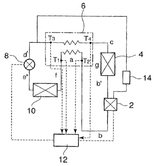
The cycle control means 12 shown in' FIG. 5 controls the flow
through the expansion valve 8 and the flow through the
compressor 2. Flow control of the compressor 2,is determined
depending on operation condition and load condition. Flow
control of the expansion valve 8 is done as follows:
Four temperature sensors are located at vapor side inlet
and outlet and liquid side inlet and outlet of the heat
exchanger 6 respectively; and vapor side inlet temperature T1
and outlet temperature T2, and liquid side inlet temperature
T4 and outlet temperature T3 are detected.
FIG.'3 is a graph showing liquid side temperature changes
and vapor side temperature changes in the regeneration heat
exchanger 6.
There may occur three states of refrigerant vapor at the
entrance to the heat exchanger 6, i.e. state of too small
dryness(excessive wetness fraction), optimal dryness(optimal
wetness fraction), and excessive dryness(too small wetness
fraction). ,
In the graph of FIG.3 are shown vapor side and liquid side
temperature change when thedryness is too small'(excessive
wetnes s. f raction ) by a curve A( broken line) and curve A' (broken
line) respectively, vapor side and liquid side temperature
change when the dryness is optimal(optimal wetness fraction)
by a curve B(solid line) and curve B' (solid line) respectively,
and vapor'side and liquid side temperature change when the
dryness is excessively large(too small wetness fraction) by
a curve C(chain line) and curve C'(chain line) respectively.
Dryness of refrigerant vapor at the inlet to the heat
exchanger 6 is controlled by controlling the flow rate of the
high-pressure refrigerant passing through the expansion valve
8 based on detected temperatures T1 - T4 shown in FIG.5.
The flow rate of the refrigerant passing through the heat
exchanger 6 is feedback-controlled based on detected
temperatures T1-T4 by reducing flow rate of the high-pressure
liquid refrigerant passing through the expansion valve 8 when
CA 02645814 2008-09-12
WO 2007/110991 PCT/JP2006/321453
29
dryness is too small(wetness fraction is excessive) as shown
by the curve A, A', that is, when temperature difference d
TA at high-temperature side exceeds a prescribed value(liquid
inlet temperature T4 - vapor outlet temperature T2 >
prescribed value(for example 5 C)) and increasing flow rate
of the high-pressure liquid refrigerant passing through the
expansion valve 8 when dryness is excessive(wetness fraction
is irisuff.icient) as shown by the curve C, C', that is, when
temperature difference d TC at low-temperature side exceeds a
prescribed value(liquid outlet temperature T3 - vapor inlet
temperature Tl > prescribed value(for example 5 C )) so that
both the temperature differences,at the high-temperature,side
and low-temperature- side of the heat exchanger 6 are kept within
a prescribed value.( for example 5 C ). By this, dryness of the
refrigerant vapor at the vapor inlet of the heat exchanger 6
can be maintained to be near proper dryness(or wetness)
fraction as shown by curve B(unless the.prescribed value of
temperature difference is zero, temperature change runs near
along the curve B)..
As shown in FIG.1 and FIG.5, when vapor side inlet
temperature Tl is equal to a dry saturated vapor temperature
Ta, and.the state of refrigerant at the liquid side outlet is
at a point d' when vapor side outlet temperature T2 is equal
to a condensation-temperature Tb.
The point d' is a state point at which enthalpy difference
is; AHba = OHcd', and the point d is a state point at which
enthalpy difference i s; vHbf = OHcd. Temperatures at point d'
and d are respectively Td' and Td.
Refrigerating capacity of the cycle when the state of
refrigerant at the vapor side inlet is shifted from the dry
saturated vapor at point a to point f at which the refrigerant
is in a wet vapor state, and further shifted beyond point a,
f will be investigated hereunder with reference to FIG.1, FIG. 2,
FIG.4, and FIG.5.
Relations between enthalpies of the refrigerant at each
state point are shown by equations (1) -(13 ) as already shown.
CA 02645814 2008-09-12
WO 2007/110991 PCT/JP2006/321453
It was recognized as shown in FIG. 4 that even if dryness changes
in the section between point. a and point f at vapor side inlet
of the heat exchanger 6, refrigerating capacity is, always
increase by Hb-Ha(=AHba); in a zone where dryness is larger than
that of at point f, refrigerating capacity decrease as shown
at point h; and iA a superheated vapor zone beyond point f,
the maximum value in the section a-f is extended when heat
amount of the superheated vapor is effectively utilized.,
By the way, the reasons' that the point f is the optimum point
in spite of the fact that refri.gerating capacity is unchanged
in the section a-f, is that dryness is the smallest (wetness '
fraction is the largest) at the,poin,t f in the section,a-f,
, so degree of cooling of the refrigerant liquid is largestand
generation of flash gas at the,expansion through the expansion
valve is the smallest (zero or extremely small), that is,'volume
change by expansion is the smallest and the occurrence of
corrosion/ erosion of the expansion valve by the flash gas is
prevented, that dryness after expansion decrease(wetness
fraction increases), so heat transfer coefficient in the.
evaporator increases and heat loss in the evaporator decreases,
etc.
In FIG.4 is shown a relation between dryness and COP and
refrigerating capacity in the vapor compression Ericsson
refrigerating cycle according to the present invention. In
the range of the section a-f, COP is constant; because
refrigerating capacity does not change in spite of different
refrigerant state at the point f at the vapor side inlet of
the regeneration heat exchanger from that at the point a, and,
as refrigerant state at inlet of the compressor is the point
b in FIG.1, the power for compression is constant.
That COP is equal to COP of the typical conventional vapor
compression refrigerating cycle at point h in FIG.4 will be
explained hereunder. In the drawing, a typical vapor
compression refrigerating cycle based on the reversed Carnot
cycle a-b-g-c-d" is shown in the P-H diagram of FIG.4, and also
the cycle a-b-b'-g-c-d-e-a(in the case of isothermal
CA 02645814 2008-09-12
WO 2007/110991 PCT/JP2006/321453
31
expansion) according to the invention is shown in broken lines,
and explanation will be done also referring to these lines.
When dryness is allowed to decrease (wetness fraction to
increase) in the section f-h, vapor outlet temperature in the
regeneration heat exchanger changes fromthe point b toward
the point a.' On the other hand, the state of outlet liquid
refrigerant in the heat.exchanger remains unchanged at point
d. When dryness at the vapor inlet in the regenerati.on heat
exchanger reaches the state point h, state at the inlet of the,
compressor comes to the point a, and increase (AHba) of the
refrigerating capacity becomes zero. That is, in this case,
operating 'condition is completely the same as that of, the
typical conventional vapor compression refrigerating cycle.
Therefore, for the same compressor, when refrigerant vapor
sucked by the compressor is in the state of the.state point
h., refrigerating capacity and COP of this cycle is the same
as those of the conventional cycle. As COP is constant and at
its maximum when the state of refrigerant at the vapor side
inlet of the heat exchanger is between the section f-a, relation
of refrigerating capacity and COP in the section f-h have
rightward rising tendency.
Therefore, here denoting dryness at the vapor side inlet
of the heat exchanger by X,- by controlling the dryness to range
from dryness at the state point h, X=Xh, with which the state
of the refrigerant vapor at the vapor side outlet of the heat
exchanger.is in its dry saturated vapor state (refrigerant
vapor at the outlet is in a state of dry saturated vapor when
the refrigerant vapor at the outlet is in a state of dry fraction
of Xh), to dryness at the state point a, i.e. X=1, with which
the temperature of the refrigerant vapor at the vapor side
outlet of the heat exchanger is at the condensation temperature
in the condenser, i. e. Xh:-!:-~Xc 1, refrigerating capacity and COP
can be increased compared with those of the typical
conventional vapor compression refrigerating cycle.
Next, results of calculation of how COP of the refrigerating
cycle varies depending on dryness of refrigerant vapor at the
CA 02645814 2008-09-12
WO 2007/110991 PCT/JP2006/321453
32
vapor side inlet of the heat exchanger are shown in'FIG.6 and
FIG.7 for a variety of refrigerants based on their physical
properties.
Here, compression power W is calculated by the following
equation (4), and specific heat and specific heat ratio of
refrigerant'at 80 C are used assuming discharge temperature
from the compressor to be about 80 C . This corresponds to the
case oil injection type screw compressors and all kind of liquid
injection type compressors are operated so that discharge
temperature is about 80 C.
W = x/(K-1) (PiVi) [ (P2/P1) (14)
where x=specific heat ratio of refrigerant vapor, P1=suction
pressure, P,,=discharge pressure, and V1=volume flow rate of
refrigerant vapor.
In FIG.6 and FIG.7, abscissas represent vapor, side outlet
temperature in the regeneration heat exchanger.-The ordinate
in FIG.6 represents COP, and the ordinate in FIG.7 represents
factors of multiplication of volumetric capacity. Calculation
was carried out with evaporation temperature(Te)of
refrigerant of -40 C , condensation temperature(Tc) of
refrigerant of 40 C , and kinds of refrigerant as parameters.
Volumetric capacity(kJ/m3) is refrigerating capacity (kW) per
unit volume flow rate (m3/s ) of refrigerant in compressor, and
the factor of multiplication means the ratio of the volumetric
capacity of this cycle to that when ammonia refrigerant is
adiabatically compressed from an evaporation temperature of
-40 C of saturated vapor state to a pressurized state at which
condensation temperature is 40 C.
Abscissas in both Figures mean that when temperature of the
abscissa is -40 C, dryness of the vapor at the vapor side inlet
of the regeneration heat exchanger is deficient(excessive in
wetness fraction), that is, this state corresponds to the point
h in FIG.4, and vapor side outlet temperature is -40 C(i..e.
suction temperature of the compressor is -40 C).
Similarly, when temperature of the abscissa is -40 C, dryness
of the vapor at the vapor side inlet of the regeneration heat
CA 02645814 2008-09-12
WO 2007/110991 - PCT/JP2006/321453
33
exchanger is that of a state between the state point a and f
in FIG.4, and vapor side outlet temperature is 40 C. That vapor
side outlet temperature is between both the temperature means
that dryness 'of the vapor at the vapor side inlet is
deficient(excessive in wetness fraction).
From FIG.6 and.FIG.7 can be recognized the following:
Among refrigerants shown in FIG.6 and FIF.7, COP of this
cycle decreases as vapor side outlet temperature in the heat
exchanger increases only when ammonia.,refrigerant(R717) is
used. From this, it is recognized that ammonia is a refrigerant
inappropriate for this cycle. COP is improved by applying this
cycle with all the refrigerants shown in FIG. 6, 7 except ammonia.
As to volumetric capacity, it increases as vapor side outlet
temperature in the heat exchanger increases by applying this
cycle with all of the refrigerants shown in FIG.6, 7 except
ammonia and R32. Volumetric capacity is largest in FIG.7 with
R32, so it,is recognized that only ammonia is inappropriate
for this cycle.
By operating the cycle of the invention at high COP condition,
COP higher than with ammonia can be attained with R600a, R134a,
and R290.
When compared in the case of compressors of the same
displacement volume, refrigerating capacity larger than that
obtained when operated with ammonia can be increased with any
of R32, R410A, R125, R134a, R507, R404, R290, and R22.
As has been described above, refrigerating capacity and COP
can be maximized by controlling dryness of the refrigerant
vapor at the entrance to the regenerating heat exchanger 6.
FIG.8 is an enlarged illustration of part Q in FIG.1. In
the drawing, an example of a partial process of process b-c,
i.e. a substitution for the isothermal process b-g is shown.
Condensation process of high temperature side isothermal
process b-c is composed of multistage adiabatic compression
processes b-bl, g2-b2, = -- , gn-bõ and multistage isobaric heat
dissipation processes b1-g2, b,-g3, ===, bn-g.
When the number of stages is increased infinitely, effect
CA 02645814 2008-09-12
WO 2007/110991 PCT/JP2006/321453
34
of adiabatic compression is eliminated and the compression
process converges into an isothermal compression process, and
the inlet temperature in the compression process and
compression 'temperature become equal to condensing
temperature Tb. This means that environmental temperature
(temperature of the ambient air) can be used as a low
temperature source needed for isothermal compression, which
is very advantageous from practical point of view. The Ericsson
cycle has isothermal proc'esses and has not adiabatic processes.
By applying multistage adiabatic compression proces,ses and
multistage heat dissipating processes, the processes can be
approximated to an isothermal compression process under the
environmental temperature, and power for compressing
refrigerant can be reduced.
Next, the refrigerating apparatus according to the present
invention will be explained referring to FIG.9-FIG,.12.
(Fitst embodiment)
FIG.9 is a schematic illustration for explaining the first
embodiment of the refrigerating apparatus. The apparatus
comprises a compressor 2 for compressing refrigerant, a
condenser 4 for cooling the refrigerant compressed.to high
pressure, a countercurrent heat exchanger (regeneration heat
exchanger) 6 for further cooling the refrigerant cooled
through the condenser 4, an expansion,valve (expansion means)
8, an evaporator 10 in which the refrigerant flowri out from
the expansion valve 8 i:s evaporated by absorbing heat from the
ambience, and a cycle control means 12 for controlling the
expansion valve and compressor 2.
A refrigerant vapor flow branched from a vapor side heat
transfer path 20 in the regeneration heat exchanger 6 at a
midway of the path 20 via a flow regulation valve 22 is
introduced to a cooling-load device 24, and refrigerant vapor
flown out form the cooling-load device 24 and flown out from
the regeneration heat exchanger 6 are sucked by the compressor
2. The cooling-load device 24 is composed of a hermetic motor
which is integrated in the compressor 2 for refrigerating/air
CA 02645814 2008-09-12
WO 2007/110991 PCT/JP2006/321453
conditioning.
According to the apparatus of. the first embodiment, the
cooling-load device 24 can be cooled by utilizing the increment
(AHba) of refrigerating capacity gained by the refrigerating
cycle applying the inversed Ericsson cycle of the invention.
Further, the apparatus is better fitted for maintaining the
cooling-load device 24 to a temperature near that of condensing
temperature Tb, for refrigerant diverted from the heat
transfer path 20 in the regeneration heat exchanger 6 is
introduced to the cooling-load device 24 via the flow
.regulati.on valve 22.
Further, dryness X of refrigerant vapor at the inlet of the
regeneration,heat exchanger 6.is controlled in a range from
Xh with which the state of the refrigerant vapor at the vapor
side outlet is in its dry saturated vapor state -and X=1 with
which the temperature of the refrigerant vapor at the vapor
side outlet is, at the condensation temperature of the
refrigerant in the condenser, that is, XhcXc 1, by the control
means 12. By controlling like this, refrigerating capacity and
COP can be increased compared with the conventional vapor
compression refrigerating cycle.
Further, the control means 12 controls by means of the flow
regulation valve 22 the flow rate of refrigerant flowing to
the cooling-load device 24 which is a herinetic motor'so that
the temperature of the refrigerant at the outlet of the hermetic
motor is maintained near the conden.sing temperature in the
condenser 4. In this way, the refrigerating apparatus of the
invention can be operated so that refrigerating capacity and
COP are at its maximum.
In the following embodiments, it is also necessary to keep
the temperature of refrigerant at the inlet of the compressor
2 always near the temperature of the condensing temperature.
(Second embodiment)
FIG. 10 is a schematic illustration for explaining the second
embodiment of the refrigerating apparatus. The vapor
compression refrigerating shown in FIG.10 is similar to that
CA 02645814 2008-09-12
WO 2007/110991 PCT/JP2006/321453
36
of FIG.9. This embodiment is characterized in that a part of
refrigerant vapor flowing out from the evaporator 10 is
diverted via a flow regulation valve 22 to be introduced to
the cooling-load device 24 and the refrigerant vapor flowing
out from the cooling-load device 24 is returned to a midway
along the vapor side heat transfer path 20 in the regeneration
heat exchanger 6 via a return path 26 or returned to the outlet
of the regeneration heat exchanger 6 for refrigerant vapor to
be introduced to the compressor 2 together with refrigerant
vapor flowing out from the regeneration heat exchanger 6. .The
cooling-load device 24 is composed of a hermetic motor which
is integrated in the compressor 2 for refrigerating/air
.conditioning.
According to the second embodiment, the cooling-load device
24 can be cooled by utilizing the increment (AHba) of
refrigerating capacity gained by the refrigerating cycle
applying the inversed Ericsson cycle of the invention as is
with the first embodiment. Furthermore, the apparatus of this
embodiment is better,suited for maintaining the cooling-load
device to still lower temperature, for a part of the refrigerant
flowing out from the evaporator 10 is diverted to be introduced
to the cooling-load device 24 directly and the cooling-load
device can be cooled effectively.
(Third embodiment)
FIG. 11 is a schematic illustration for explaining the third
embodiment of the refrigerating apparatus. The vapor
compression refrigerating shown in FIG.11 is the similar to
that of FIG.9. This embodiment is characterized in that
refrigerant vapor flow branched from a vapor side heat transfer
path 20 in the regeneration heat exchanger 6 at a midway (at
a position 32) of the path 20 via a flow regulation valve 22
is introduced to a cooling-load device 28, and refrigerant
vapor flowing out from the cooling-load device 28 is introduced
to the heat transfer path 20 at a position downstream from the
position 32 from which refrigerant was diverted via a return
path 30. The cooling-load device 28 is a generally used
CA 02645814 2008-09-12
WO 2007/110991 PCT/JP2006/321453
37
cooling-load device for cooling a preparatory cooling room and
anterior room of a cold store, for air-conditioning a storage
room, etc.
According to the third embodiment, the cooling-load device
28 can be cooled; by utilizing the increment (AHba) of
refrigerating capacity gained by therefrigerating cycle
applying the inversed Ericsson cycle of the invention as is
with the first embodiment: Further; with this embodiment,
refrigerant diverted at the branch point 32 is flown through
the cooling-load device 28 and then all the refrigerant flown
through the cooling-load device 28 is,returned again to the
regene'ration heat exchanger 6 from which then introduced to
the inlet of the compressor 2, so refrigerant vapor is returned
to the compressor 2 after sufficiently adjusted in temperature
in the regeneration heat exchanger 6. Therefore, compared with
the first and second embodiments in which the diverted
ref rigerant interflows into the refrigerant flow from the
regeneration heat exchanger 6 at the inlet of the compressor
2, temperature of refrigerant can be adjusted in a wider range
and a wide range of temperatures of cooling loads from
evaporation temperature in the evaporator 10 to condensing
temperature in the condenser can be accommodated to by the
apparatus of the embodiment.
(Fourth embodiment)
FIG.12 is a schematic illustration for explaining the third
embodiment of the refrigerating apparatus. The vapor
compression refrigerating shown in FIG.12 is the similar to
that of FIG.9. This embodiment is composed such that all of
refrigerant vapor flowing in the evaporator 10 is introduced
into the cooling-load device 28, and all of refrigerant vapor
flowing out from the cooling-load device 28 is introduced to
heat transfer path 20 in the refrigeration heat exchanger 6
and then introduced to the inlet of the compressor. The
cooling-load device 28 is a generally used cooling-load device
for cooling a preparatory cooling room and anterior room of
a cold store, for air-conditioning a storage room, etc.
CA 02645814 2008-09-12
WO 2007/110991 PCT/JP2006/321453
38
According to the fourth embodiment, as dryness of
refrigerant at vapor side inlet is controlled by controlling
the flow rate regulation valve 8 by the control means 12 so
that dryness is in the range between dryness at the state point
Xh, with which the state of the refrigerant vapor at the vapor
side outlet of the heat exchanger is in its dry saturated vapor
state(refrigerant vapor at the outlet is in a state of'dry
saturated.vapor when the refrigerant vapor at the outlet is
in a state of dry fraction of Xh), and dryness at the state
point a, i. e. X=1, with which the temperature of the refrigerant
vapor at the vapor side outlet of the heat exchanger is at the
condensation temperature in the condenser, i.e. XhcXc 1, the
apparatus of this embodiment can accommodate to a variety of
cooling-load device 28 for cooling to a relatively low
temperature range near that of evaporation temperature in the
evaporator 10, and refrigerating system can be simplified.
Industrial Applicability
By the vapor compression refrigerating cycle,, control
methods thereof, and refrigerating apparatuses according to
the- present invention, efficiency and advantage can be
realized which are superior than those of the conventional
vapor compression refrigerating cycle by modifying the basic
cycle for the vapor, compression refrigerating cycle, that is,
by converting the reversed Carnot cycle as a basic cycle of
the vapor 'compression refrigerating cycle to the reversed
Ericsson cycle as a basic cycle of the vapor compression
refrigerating cycle. The present invention can be applied
advantageously to refrigerating apparatuses, air conditioners,
etc.