Note: Descriptions are shown in the official language in which they were submitted.
CA 02645840 2008-12-04
END CAP CLAMPING AND SEALING SYSTEM
BACKGROUND OF THE INVENTION
[0001] This invention relates generally to systems for sealing access ports
and
other openings in piping systems and more particuiariy to an end cap cover for
a check
vaive assembly where the end cap cover is held in place by a circumferential
clamp.
[00021 It is known to seal the open ends of piping and ports formed in pipe
fixtures using removabie caps. In this regard, the end or port can be accessed
by
removing ihe cap for replacing the end cap with another fixture or for
providing access
to a space within the piping of frxture_ End caps are used In fixtures such as
check
valve assembiies for sealing an access port formed in a check valve housing.
Generally such end caps are metaRic, and a gasket or o-ring for sealing is
positioned
between a flange formed on the end cap and a flange formed on the check valve
assembly.
[0003] Conventional end caps are often attached to pipes by engaging retaining
rings, ciamps, cooperating threaded surfaces formed on the pipe end and on the
cap,
and the like. In each case the gasket or o-ring for sealing is positioned
between the
flange of the end cap and the flange of the fixture.
10004] A problem with such known end caps is that in order for the gasket or o-
ring to be seaiingiy engaged, the o-ring must be compressed between the
flanges
around the entire circumference of the end cap. Such uniform compression can
be
difficult to obtain. Another problem with known end cap sealing systems is
that the end
caps are metallic. Metallic end caps can be costly to manufacture and
contribute
significantly to the weight of the fixture, such as a check vatve assembly, in
which the
end cap is being used.
1970177 Page 1 of 15
CA 02645840 2008-12-04
BRIEF SUMMARY OF THE INVENTION
[0005] Accordingly, there is a need to provide an end cap sealing system that
is
lighter, less costly to manufacture, and more reliably sealed than known end
cap
sealing systems.
[0006] Therefore it is an object of the present invention to provide an end
cap
sealing system that includes an end cap having polymeric components.
[0007] Therefore it is an object of the present invention to provide an end
cap
sealing system that is lighter in weight than conventional end cap sealing
systems.
[0008] Therefore it is an object of the present invention to provide a check
valve
assembly that is lighter in welght than conventional check valve assemblies.
[0009] Therefore it is an object of the present invention to provide an end
cap
sealing assembly having an end cap core that is non metallic.
[0010] Therefore it is an object of the present invention to provide an end
cap
sealing system having a gasket or o-ring for sealing that is spaced-away from
flanges
formed on an end cap such that the gasket or o-ring can engage an interior
surface of
the piping end or fixture being sealed.
[0011] Therefore there is provided an end cap sealing system for sealing an
open piping end. The end cap sealing system includes an end cap having an end
cap
core. The end cap core has a generally cylindrical end with a circumferential
groove
formed around the exterior thereof and a closed end that defines a generally
circular
rim. An o-ring is positioned within the groove for sealingly engaging an
interior wall of
the piping open end. The end cap sealing system also includes a generally
circular
clamp having a channel formed therein for capturing the rim and a flange
formed on the
check valve. The o-ring being spaced-apart from the rim of the end cap core.
1970/77 Page 2 of 15
CA 02645840 2008-12-04
[0012] In accordance with one embodiment of the present invention, a generally
circular clamp having a channel formed therein for capturing the rim and a
flange
formecf on the open piping end is provided.
[0013] in accordance with another embodiment of the invention, the open piping
end is formed on a fixture.
[0014] In accordance with another embodiment of the invention, the fixture is
a
check vaive and the open piping end is an access port.
[0015] In accordance with another embodiment of the invention, the flange is
formed around the access port and defines a surface that engages the lip of
the end
cap.
[0016] In accordance with another embodiment of the invention, the end cap
includes a polymeric end cap core.
[0017] In accordance with another embodiment of the invention, a metallic end
cap cover is provided.
[0018] In accordance with another embodiment of the invention, the end cap
cover is attached to the end cap core by a screw.
[0019] In accordance with another embodiment of the invention, the end cap
cover is attached to the end cap core by a valve having a portion that extends
through
the end cap core.
[0020] In accordance with another embodiment of the invention, there is
provided
a method for using an end cap sealing system to seal open piping end. A clamp
and an
end cap having an end cap core are provided. The end cap core has a generaiiy
cylindrical end with a circumferential groove formed around the exterior
thereof and a
1970/77' Page 3 of 15
CA 02645840 2008-12-04
closed end that defines a generally circular rim. An o-ring is positioned
within the
groove for sealingly engaging an interior wall of the open piping end. The end
cap
sealing system also includes a generafly circular clamp having a channel
formed therein
for capturing the rim and a flange formed on the check valve. The o-ring being
spaced-
apart from the rim of the end cap core.
BRIEF DESCRIPTION OF THE DRAWINGS
[0021] The subject matter that is regarded as the invention may be best
understood by reference to the following description taken in conjunction with
the
accompanying drawing figures in which:
[0022] Figure 1 is a sectional side view of a check vaive assembly that
includes
end cap covers according to one embodiment of the present invention;
[0023] Figure 2 is a partial sectional view of the check valve assembly and an
end cap as shown in figure 1;
[0024] Figure 3 is a top view of the end cap shown in figure 2;
[0025] Figure 4 is a perspective view of an end cap according to another
embodiment of the present Invention having a valve positioned therein ;
[0026] Figure 5 is a side view of the end cap shcwn in figure 2; and
[0027] Figure 6 is a top view of the end cap shown in figure 2.
DETAILED DESCRIPTION OF THE INVENTION
[0028] Referring to the drawings wherein identical reference numerals denote
the
same elements throughout the various views, Figure 1 illustrates a check valve
1970/77 Page 4 of 15
CA 02645840 2008-12-04
assembly 10 that includes two end caps 70A and 70B according to the present
invention. The end caps 70A and 708 are substantially similar such that the
end cap
70B can be understood from a description of the end cap 70A with the exception
of an
alternative configuration described further below.
[0029] The check valve assembly 10 includes a pair of check valves 30A and
30B positioned in series with each other. The check valves 30A and 30B are
substantially the same such that the check valve 30B can be understood with
regard to
the foliowing description of the check valve 30A. Each check valve 30 includes
a
housing 32 formed by walls 34. An interior surface of the walls 34 define an
interior
region 36. An inlet 38 and an outlet 42 are defined in the housing 32 for
permitting fluid
flow from an upstream side to a downstream side of the housing 32. An access
port
44 is defined in housing 32 for permitting access to the interior region 36,
and a flange
45 is formed around the access port 44 as described further below. A valve
mechanism 46 is positioned within the interior region 36 for controlling fluid
flow
therethrough. In the illustrated embodiment, the valve mechanism 46 is a check
valve.
It is appreciated that various types of devices can be recefved within the
interior region
36. By way of example and not limitation, the types of flow control devices
that coufd
be received within interior region 36 include the following: various types of
vahies
including swing-type check valves, flow meters, sample collection devices,
sensors for
monitoring fluid qualities, flow control devices, flow restrictors, and
combinations
thereof. The valve mechanism 46 includes a valve seat 48 positioned in the
interior
region 36 of the valve housing 32, and a seal retainer 52 positioned in the
Interior
region 36 downstream from the valve seat 48. The seal retainer 52 is mounted
on a
stem 54.
[0030) The stem 54 and the seal retainer 52 are axially movable away from the
valve seat 48 in response to fluid flow from the inlet 38 to the outiet 42,
i.e., in a
downstream direction. The seal retainer 52 and the stem 54 are also axially
movable
toward the valve seat 48 in response to fluid flow from the outiet 42 to the
inlet 38, i.e.,
in an upstream direction. The seal retainer 52 and the stem 54 are configured
to be
1970/77 Page 5 of 15
CA 02645840 2008-12-04
positioned in sealing engagement against the valve seat 48 in the absence of
fluid flow.
A plurality of springs 55 connect the stem 54 to the interior of the walls 34.
The
springs 55 are positioned in radial opposition to one another, and each spring
55 has
one end pivotally connected to the valve seat 48 and another end pivotally
connected to
the stem 54. The springs 55 are configured to maintain the seal retainer 52 in
sealing
engagement with the valve seat 48 in the absence of fluid flow.
[0031] As can be seen in ftgure 1, the valve mechanism 46 is positioned within
a
cage 56 that is configured to be received by the interior region 36 through
access port
44 and retained within region 36 by end cap 70A.
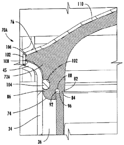
[0032} Referring to figures i and 2, the end cap 70A is generally cup-shaped
and
includes an end cap core 72A and a rnetallic end cap cover 110. The end cap
core 72A
has an open end 74 and a closed end 76 and is configured such that the open
end 74
can be received within the access port 44 of the check valve 30. The end cap
core 72A
is oriented such that the open end 74 is oriented such that it is open toward
the valve
mechanism 46. The end cap core 72A is generally cylindrical around an axis
near the
open end 74, An inner wall 82 is formed on the open and 74 and extends away
from
the open end 74 coaxial to the axis of the end cap core 72A. A land area 84 is
formed
on inner wall 82. An outer wail 86 is positioned concentrically with the inner
wall 82 and
extends from the end cap core 72A further than the inner wall 82. The inner
wall 82
and the outer wall 86 together define an annular channel 88 that is configured
to
receive a gasket 92.
[0033j The gasket 92 Is generally circular and has an outer ring portion
configured to be received within the annular channel 88. An inner seal portion
96
extends from the ring portion of the gasket 92, and is configured to extend
across the
land area 84 of the inner wall 82. The inner wall 82, the outer wall 86, and
the gasket
92 are configured such that the gasket 92 is operable to sealingly engage the
cage 56
when the end cap 70A is positioned within access port 44.
1970l77 Page 6 of 16
CA 02645840 2008-12-04
[0034] Continuing to refer to figures 1 and 2, a circumferential groove 102 is
formed around the cylindricai portion of the end cap core 72A. In the
illustrated
embodiment, the circumferential groove 102 is spaced-away from the open end 74
of
the end cap core 72A and from a rim 106 of the end cap core 72A (described
below). It
should be appreciated that the groove 102 could be formed on the outer wall 86
of the
end cap core 72A. The groove 102 is configured to receive an o-ring 104. In
one
embodiment, the o-ring 104 Is formed of a res(Iient polymeric material such as
EPDM.
The o-ring 104 could afso.be formed of suitable sealing materials such as buna-
N,
silicone rubber, Viton T"", and the like.
[00331 The end cap core 72A flares outwardly to the rim 106 at a closed end 76
that is posttioned opposite the open end 74. The Hm 106 extends around the
entire
circumference of the end cap core 72A and has two opposed recesses 108 formed
therein that are dimensioned to receive a tool such as a screw driver. In the
illustrated
embodiment, the closed end 76 is generally dome-shaped and extends away from
the
intertor region 36. It should be appreciated that the closed end 76 could be
generally
flat or formed such that it extends into the interior region 36 of housing 32.
[0036] In the illustrated embodiment, the end cap core 72A is formed of a
polymeric material. By way of example and not limitation, the end cap core 72A
can be
formed of one of nory f T'", a polysulfone, an acetal, a metal, a ceramic or a
combination
thereof.
(00371 The end cap cover 110 is configured to fit over the closed end 76 of
the
end cap core 72A. In the illustrated embodiment, the end cap cover 110 closely
conforms to the shape of the closed end 76. As shown in figure 3, a screw 112
is
provided to attach the and cap cover 110 to the end cap core 72A in one
embodiment.
Referring to an aiternative configuration shown in figure 4, a test cock 114
is attached
to the end cap core 72 B of the end cap 70B. A nut 116 is engaged with a
portion of
the test cock 1114 that extends through the end cap cover 110, and Is received
within a
recess 118 formed i'n the end cap core 72B and shown in figure 6. RespecQve
portions
1970177 Page 7 of 15
CA 02645840 2008-12-04
of the test cock 114 and the end cap core 72B are configured to capture the
end cap
cover 110 and to retain it against the end cap cover 110. It should be
appreciated that
some ernbodiments of the present invention do not include an end cap cover
110. In
some embodiments end cap cover 110 is integrally formed wfth end cap 70.
[0038] Referring now to figure 3, a clamp 122 is configured to capture the end
cap 70A and a flange 45 formed around the access port 44. The clamp 122 is
generally circular and has a first end 124 and a second end 126. A groove 102
is
formed on the interior of the clamp 122 and is configured to receive rim 106
of the end
cap 70A. A pin 128 is repositionabiy attached to first end 124 and is
configured to
engage second end 126 such that clamp 122 can be quickly secured around the
flange
45 of the access port 44 and the rim 106 of the end cap 70. In this manner,
end cap 70
can be attached to housing 32 of the check valve 30.
[0039] The present invention can be better understood from a description of
the
operation of end cap 70. As indicated above, end cap 70 is used to seal
openings in
pipes, fixtures, or tubes such as the access port 44. Prior to placing end cap
70 within
access port 44, an o-ring 104 is positioned with in groove 102 and a gasket 92
is
positioned within channel 88. In the illustrated embodiment, the valve
mechanism 46 is
positioned within cage 56 that is then placed within interior region 36
through access
port 44. After cage 56 and valve mechanism 46 are positioned within interior
region 36,
end cap 70 is positioned such that open end 74 extends through access port 44
and o-
'ring 104 is in sealing engagement with walls 34. As Indicated above, o-ring
104 is
formed of a rnaterial that is deformable for providing a sealing engagement
between
end cap 70 and walls 34. When the end cap 70 is positioned within the access
port 44,
the lip 106 is near the flange 45 of the access port 44.
[0040] The clamp 122 is then place around end cap 70 and access port 44 such
that both the flange 45 and the lip 106 are captured within channe188. The pin
128 is
engaged with second end 126 such that clamp 122 is secured around the flange
45 of
1970/77 Page 8 of 15
CA 02645840 2008-12-04
the access port 44 and the rim 106 of the end cap 70. In this manner, end cap
70 is
attached to housing 32 of the check valve 30.
[0041] The foregoing has described an end cap sealing system for an check
valve. While specific embodiments of the present invention have been
described, it will
be apparent to those skilled in the art that various modifications thereto can
be made
without depardng from the spirit and scope of the Invention. Accordingly, the
foregoing
description of the preferred embodiment of the invention and the best mode for
practk;ing the invention are provided for the purpose of illustration only and
not for the
purpose of limitation.
1970/77 Page 9 of 15