Note: Descriptions are shown in the official language in which they were submitted.
CA 02645857 2008-09-12
WO 2007/094574 PCT/KR2007/000486
1
Description
AN IMPLANT DRILL
Technical Field
[1] The present invention relates to a dental implant drill, and more
particularly, to an
implant drill for maxillary sinus lifting, which is capable of easily and
simply boring
the maxillary bone, without damaging the lining membrane of the maxillary
sinus, to
easily operate the maxillary sinus lifting and to expand a boring part of the
maxillary
bone for implant placement.
Background Art
[2] Today, the implant operation for placing an artificial tooth has been
rapidly spread.
[3] However, quite a number of patients have the mouth structures with
difficult in
performing the implant operation. Some dentists are reluctant to perform the
implant
operation in these patients.
[4] Specifically, when a remaining bone in a posterior region where the
maxillary sinus
is positioned is insufficient, it is very hard to place an implant. In this
case, after a
space is secured by lifting the lining membrane of the maxillary sinus, a bone
is
transplanted in the secured space and then an implant is placed to be embedded
therein.
This method of placing an implant is divided into two manners, such as a
vertical
approach manner and a side approach manner.
[5] The vertical approach manner is used when the remaining bone is certainly
secured
in a part for the implant operation (that is, when the thickness of the
remaining bone is
4mm or above). In this case, a device, such as an osteotome (a chisel and a
mallet), is
used to tap the maxillary bone several times, and bore an aperture being 2 to
3 mm in
diameter into the maxillary bone, without damaging the lining membrane of the
maxillary sinus, and a transplant bone is little by little inserted into the
aperture.
[6] In this vertical approach manner, since the surgical operation part is
narrow, the part
less swells after the operation. However, since it is impossible to directly
see the lining
membrane of the maxillary sinus during the surgical operation, a dentist needs
to very
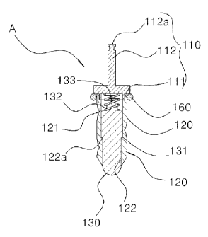
carefully perform the operation while checking an operation process by X-rays.
Therefore, a long time is required for the surgical operation. Moreover, a
shock during
the operation process may cause a very unpleasant feeling to a patient.
[7] The side approach manner is used when the remaining bone is very
insufficient in
the part for the implant operation (that is, when the thickness of the
remaining bone is
4mm or below). In this case, an aperture (window) is formed on the side of the
maxillary sinus and the lining membrane of the maxillary sinus is lifted to
transplant a
bone.
CA 02645857 2008-09-12
WO 2007/094574 PCT/KR2007/000486
2
[8] In the side approach manner, since a dentist lifts the lining membrane of
the
maxillary sinus while directly seeing it during the surgical operation, the
lining
membrane of the maxillary sinus is less damaged. Even if the lining membrane
of the
maxillary sinus is damaged, a post-treatment is possible. Further, since a
bone
transplant material in a desired amount can be promptly inserted at once, the
progress
thereof is fast.
[9] However, the surgical operation is difficult and a valve needs to be
formed.
Therefore, after the surgical operation, a patient has a severe edema. Due to
these
reasons, the side approach manner is in fact avoided.
[10] Meantime, research has been conducted for a maxillary sinus lifting
technique using
a general implant drill and a trephine drill shown in FIGS. 1 and 2, together
with the
above-mentioned methods.
[11] A patient has less aversion to the surgical operation using the implant
drill. Further,
the maxillary bone can be easily and fast bored. However, when the boring of
the
maxillary bone is completed by the rotation of a drill bit, since no means is
prepared to
prevent a tip of the drill bit from contacting with the lining membrane of the
maxillary
sinus, the lining membrane of maxillary sinus may be damaged by being torn or
rolled
by the tip of the drill bit. Therefore, it can be said that the maxillary
sinus lifting
technique using a drill is almost impossible at present.
Disclosure of Invention
Technical Problem
[12] Therefore, the present invention is directed to provide an implant drill
for maxillary
sinus lifting, which is capable of easily and simply boring the maxillary
bone, without
damaging the lining membrane of the maxillary sinus, to easily operate the
maxillary
sinus lifting.
[13] Another object of the present invention is to provide an implant drill
for maxillary
sinus lifting, which is capable of easily and simply expanding a boring part
of the
maxillary bone for implant placement, without damaging the lining membrane of
the
maxillary sinus.
[14] Another object of the present invention is to provide an implant drill
which is
capable of previously and easily checking a position for boring the maxillary
bone and
visually marking a size of an artificial tooth and a position for placing an
artificial
tooth root, both being checked, at a part for implant operation.
Technical Solution
[15] In accordance with an exemplary embodiment, the present invention
provides an
implant drill for maxillary sinus lifting, which includes a cutting groove
formed on an
outer circumference surface of a cylindrical body, and a central shaft with a
shank and
CA 02645857 2008-09-12
WO 2007/094574 PCT/KR2007/000486
3
which is mounted onto a general dental hand piece, comprising: a protrusion
member
elastically positioned in the body and moving forward and backward at an end
of the
drill in a length direction.
[16] Then, the front end of the protrusion member may be processed to be
round, and the
protrusion member may be inserted into a through-aperture formed in the body
in the
length direction so as to be supported by a spring.
[17] Further, the protrusion member may include a stop rod so that the
protrusion
member is controllably inserted into the drill at a predetermined depth.
[18] Further, the protrusion member may include an end protrusion and the
through-
aperture may include an inner protrusion so that the end protrusion engages
with the
inner protrusion, to prevent the protrusion member from separating from the
through-
aperture.
[19] Further, the outer circumference surface of the body may include a flange
so that
the drill is controllably inserted at a predetermined length.
[20] Further, the outer circumference surface of the body may further include
an impact
absorber controlling the length of the drill to be inserted to be shorter and
absorbing
impact when the drill is inserted at the controlled length.
[21] In accordance with another exemplary embodiment, the present invention
provides
an implant drill for maxillary sinus lifting, which is an implant trephine
drill including
a cutting groove formed on an end of a cylindrical body, and a central shaft
with a
shank and mounted onto a general dental hand piece, comprising: a protrusion
member
elastically positioned in the cylindrical body and moving forward and backward
at a
center of the cutting groove formed on the end of the cylindrical body in a
length
direction.
[22] Then, the protrusion member may be inserted into the cylindrical body so
as to be
supported by a spring; and the protrusion member may include an end protrusion
and
the cylindrical body may include an inner protrusion so that the end
protrusion engages
with the inner protrusion, to prevent the protrusion member from separating
from the
inside of the cylindrical body.
[23] Further, the outer circumference surface of the body may include a flange
so that
the drill is controllably inserted at a predetermined length.
[24] Further, the outer circumference surface of the body may further include
an impact
absorber controlling the length of the drill to be shorter and absorbing
impact when the
drill is inserted at the controlled length.
[25] In accordance with another exemplary embodiment, the present invention
provides
an implant drill for maxillary sinus lifting, which includes a cutting groove
formed on
an outer circumference surface of a tapered cylindrical body, and a central
shaft with a
shank and which is mounted onto a general dental hand piece, comprising: a
lifting
CA 02645857 2008-09-12
WO 2007/094574 PCT/KR2007/000486
4
member positioned at an drill end of the body, so as to be free from rotation
of the
drill.
[26] Then, the front end of the lifting member may be processed to be round,
and the
lifting member may have a shape being wide at both end parts and narrow in a
middle
part so that the middle part is hinge-coupled at an end of the drill, and the
lifting
member with a first end positioned outside the drill and a second end
positioned inside
the drill may be free from the rotation of the drill.
[27] Further, the second end of the lifting member, positioned inside the
drill, may have
a conical shape, and the apex part of the second end may be supported inside
the drill.
[28] Further, the outer circumference surface of the tapered cylindrical body
may
include a flange so that the drill is controllably inserted at a predetermined
length.
[29] In accordance with another exemplary embodiment, the present invention
provides
an implant drill for maxillary sinus lifting, comprising: a connection shaft
with a shank
to be mounted onto a dental hand piece, and a cylindrical body to which the
connection
shaft is fixedly positioned, and the connection shaft is vertically positioned
at the
center on the body, and the body includes a recessed opening formed at a pre-
determined depth from the lower end of the body, a round blade in a saw-
toothed shape
continuously formed along the edge of the recessed opening, and a drill bit
positioned
at the center of the recessed opening in a vertical direction.
[30] Then, in the body, the depth of the recessed opening may be same as or
greater than
the height of the round blade, and the lower end of drill bit may protrude
further than
the lower end of the round blade.
[31] Further, the body may be any one selected from a mini type, a regular
type and a
wide type which are different from one another in the width of the body.
Brief Description of the Drawings
[32] The above and other features and advantages of the present invention will
become
more apparent to those of ordinary skill in the art by describing in detail
preferred
exemplary embodiments thereof with reference to the attached drawings in
which:
[33] FIG. 1 is a front view of a conventional dental drill;
[34] FIG. 2 is a perspective view of a conventional trephine drill;
[35] FIG. 3 is a perspective view of an implant drill for maxillary sinus
lifting according
to an exemplary embodiment of the present invention;
[36] FIG. 4 is a sectional view illustrating a connection state of the implant
drill for
maxillary sinus lifting according to an exemplary embodiment of the present
invention;
[37] FIGS. 5 through 8 are views illustrating an operation state of the
implant drill for
maxillary sinus lifting according to an exemplary embodiment of the present
invention;
[38] FIG. 9 is a perspective view of a modification of the implant drill for
maxillary
CA 02645857 2008-09-12
WO 2007/094574 PCT/KR2007/000486
sinus lifting according to the present invention;
[39] FIG. 10 is a perspective view of an implant drill for maxillary sinus
lifting
according to another exemplary embodiment of the present invention;
[40] FIG. 11 is a sectional view illustrating a connection state of the
implant drill for
maxillary sinus lifting according to another exemplary embodiment of the
present
invention;
[41] FIGS. 12 through 15 are views illustrating an operation state of the
implant drill for
maxillary sinus lifting according to another exemplary embodiment of the
present
invention;
[42] FIGS. 16 and 17 are sectional views illustrating examples of an impact
absorber
further included in the implant drill of FIG. 10;
[43] FIG. 18 is a perspective view of an implant drill for maxillary sinus
lifting
according to another exemplary embodiment of the present invention;
[44] FIG. 19 is a sectional view illustrating a connection state of the
implant drill for
maxillary sinus lifting according to another exemplary embodiment of the
present
invention;
[45] FIGS. 20 through 23 are views illustrating an operation state of the
implant drill for
maxillary sinus lifting according to another exemplary embodiment of the
present
invention;
[46] FIG. 24 is a perspective view of an implant drill for maxillary sinus
lifting
according to another exemplary embodiment of the present invention;
[47] FIG. 25 is a sectional view of the implant drill for maxillary sinus
lifting according
to another exemplary embodiment of the present invention;
[48] FIG. 26 is a view illustrating a use state of the implant drill for
maxillary sinus
lifting according to another exemplary embodiment of the present invention;
[49] FIG. 27 is a view illustrating an operation state of the implant drill
for maxillary
sinus lifting according to another exemplary embodiment of the present
invention; and
[50] FIG. 28 is a plan view illustrating a marking state by the implant drill
for maxillary
sinus lifting according to another exemplary embodiment of the present
invention.
Mode for the Invention
[51] The present invention will now be described more fully hereinafter with
reference
to the accompanying drawings, in which preferred exemplary embodiments of the
invention are shown.
[52] FIGS. 3 through 8 are views for explaining an implant drill A for
maxillary sinus
lifting according to an exemplary embodiment of the present invention.
[53] As illustrated in FIG. 3, the implant drill A comprises a connector 110,
a drill bit
120 and a protrusion member 130.
CA 02645857 2008-09-12
WO 2007/094574 PCT/KR2007/000486
6
[54] The connector 110 has a disc shape with the diameter within the range of
4 to 5mm
and includes a securing rim 111, a shank 112a and a central shaft 112. The
securing
rim 111 in a round shape with the outer diameter smaller than the outer
diameter of the
connector 110 is formed under the bottom surface of the connector 110. The
central
shaft 112 with the shank 112a is positioned at the center on the top surface
of the
connector 110.
[55] The drill bit 120 has a cylindrical shape with the diameter of about 3mm,
which is
little smaller than the diameter of the connector 110. The drill bit 120
includes a spiral
cutting groove 121 and a through-aperture 122. The spiral cutting groove 121
is
formed on the outer circumference surface of a body 120'. The through-aperture
122
with the diameter of about 2mm is formed at the center part in a vertical
direction and
is extended vertically.
[56] The protrusion member 130 has a round rod shape with the diameter being
same as
or smaller than the diameter of the through-aperture 122 of the drill bit 120.
A front
end of the protrusion member 130 is processed to be round. A stop rod 133
protrudes
at a predetermined length at the other end of the protrusion member 130 and
the
protrusion member 130 contacts with a spring 132 surrounding the outside of
the stop
rod 133. Therefore, the protrusion member 130 is forward or backward movable
by the
elasticity of the spring 132 within a predetermined range.
[57] The protrusion member 130 is positioned in the through-aperture 122 of
the drill bit
120.
[58] As illustrated in FIG. 4, the round front end of the protrusion member
130 is
positioned to be exposed out of the drill bit 120, and the spring 132 is
positioned in the
other end of the protrusion member 130 and is supported by the connector 110.
[59] The upper end of the drill bit 120 in which the protrusion member 130 is
positioned
is combined with the securing rim 111 of the connector 110, so that the drill
bit 120 is
integral with the connector 110. The securing rim 111 of the connector 110 may
be
combined with the upper end of the drill bit 120 by using a screw or by
welding if a
connecting force is secured at a predetermined level.
[60] A process of boring the maxillary bone, using the implant drill A
according to the
exemplary embodiment of the present invention is performed in the order of
FIGS. 5
through 8 and will be described in detail.
[61] The shank 112a of the connector 110 is mounted onto a dental hand piece
driving
part, so that the entire implant drill A is rotated when power is applied. As
illustrated in
FIG. 5, the tip of the drill bit 120 is allowed to approach to a part for
surgical
operation.
[62] After a dentist applies a force so that the tip of the drill bit 120 is
secured against to
the part for the surgical operation, the power is applied to the hand piece to
rotate the
CA 02645857 2008-09-12
WO 2007/094574 PCT/KR2007/000486
7
implant drill A.
[63] Then, as illustrated in FIG. 6, since the spring 132 positioned at the
back of the drill
bit 120 is pressed by contact with the maxillary bone 140 and the protrusion
member
130 partially exposed in the front of the drill bit 120 is pushed backward,
the tip of the
drill bit 120 surrounding the protrusion member 130 drills the maxillary bone
140 to
perfonn the boring.
[64] Then, as the protrusion member 130 is pushed backward at a predetermined
length,
the stop rod 133 contacts with the connector 110 so that the protrusion member
130 is
controllably inserted at a constant length. This prevents powered bones from
being
inserted in the front end of the protrusion member 130.
[65] When the boring of the maxillary bone 140 is completed and the tip of the
drill bit
120 reaches the lining membrane 150 of the maxillary sinus in a state
surrounding an
empty space, the pressure to the protrusion member 130 by the maxillary bone
140 is
momentarily released. Therefore, as illustrated in FIG. 7, the protrusion
member 130
protrudes forwardly by the elasticity of the spring 132 and lifts the lining
membrane
150 of the maxillary sinus 150 towards the empty space. This easily secures a
space for
inserting a bone transplant material.
[66] While the protrusion member 130 protrudes from the inside of the through-
aperture
122 of the drill bit 120 and contacts with the lining membrane 150 of the
maxillary
sinus, the front end of the protrusion member 130 may damage the lining
membrane
150 of the maxillary sinus. However, in accordance with the embodiment of the
present invention, since the front end of the protrusion member 130 is
processed to be
round, the lining membrane 150 of the maxillary sinus is prevented from being
damaged by the front end of the protrusion member 130.
[67] An end protrusion 131 is formed in the middle of the protrusion member
130 in a
direction of the length of the protrusion member 130. An inner protrusion 122a
is
formed in the middle of the through-aperture 122 of the drill bit 120 in a
direction of
the length of the drill bit 120. Therefore, since the end protrusion 131
engages with the
inner protrusion 122a, the protrusion member 130 does not separate from the
inside of
the through-aperture 122 and the protrusion member 130 protrudes within a
constant
range of protrusion.
[68] After the drill bit 120 bores the maxillary bone 140 and the protrusion
member 130
lifts the lining membrane 150 of the maxillary sinus, since the dentist still
pushes the
implant drill A, the drill bit 120 may further progress towards the direction
in which
the dentist applies the force, i.e., the maxillary sinus. However, in
accordance with the
embodiment of the present invention, as illustrated in FIG. 8, even though the
drill bit
120 further progress, the connector 110 with the greater diameter than the
diameter of
the drill bit 120 is limited by the maxillary bone 140 around the point at
which the
CA 02645857 2008-09-12
WO 2007/094574 PCT/KR2007/000486
8
boring is started. Therefore, the drill bit 120 cannot be further progressed,
and the
extent that the drill bit 120 is inserted into the maxillary bone 140 can be
limited.
[69] If necessary, an impact absorber in a donut shape may be mounted onto the
outer
diameter of the drill bit 120, so that the length of the drill bit 120 being
inserted into
the maxillary bone 140 can be controlled to be shorter and, when the drill bit
120 is
inserted at a desired length, the impact by the maxillary bone 140 can be
absorbed. An
example of the impact absorber may be a rubber ring 160 illustrated in FIG. 4,
and this
rubber ring 160 is sufficiently used for that purpose.
[70] The drill bit 120 according to the exemplary embodiment of the present
invention
may not have the spiral shape and therefore it may have a parallel shape as
illustrated
in FIG. 9.
[71] FIGS. 10 through 16 are views for explaining an implant trephine drill B
for
maxillary sinus lifting according to another exemplary embodiment of the
present
invention.
[72] As illustrated in FIG. 10, the implant trephine drill B comprises a
connector 210, a
drill bit 220 and a protrusion member 230.
[73] Unlike a general drill for boring in a round shape, since the trephine
drill includes a
cutting groove in a round shape on a cylindrical shape end only and performs
boring,
the trephine drill extracts a round shape self-bone corresponding to the
middle part of
the cutting groove.
[74] The connector 210 has a disc shape with the diameter within the range of
4 to 5mm
and includes a securing rim 211, a shank 212a and a central shaft 212. The
securing
rim 211 in a round shape with the outer diameter smaller than the outer
diameter of the
connector 210 is formed under the bottom surface of the connector 210. The
central
shaft 212 with the shank 212a is positioned at the center on the top surface
of the
connector 210.
[75] The drill bit 220 has a cylindrical shape with the diameter of about 3mm,
which is
little smaller than the diameter of the connector 210. The drill bit 220
includes a saw-
toothed cutting groove 221 and a through-aperture 222. The saw-toothed groove
221 is
formed in a round shape at an end of a cylindrical shaped body 220'. The
through-
aperture 222 with the diameter of about 2mm is formed at the center part in a
vertical
direction and is extended vertically.
[76] The protrusion member 230 has a round rod shape with the diameter being
same as
or smaller than the diameter of the through-aperture 222 of the drill bit 220.
A front
end of the protrusion member 230 is processed to be round. The other end of
the
protrusion member 230 is in contact with a spring 232. The protrusion member
230 is
forward or backward movable by the elasticity of the spring 232 within a pre-
determined range.
CA 02645857 2008-09-12
WO 2007/094574 PCT/KR2007/000486
9
[77] The protrusion member 230 is positioned in the through-aperture 222 of
the drill bit
220.
[78] As illustrated in FIG. 11, the round front end of the protrusion member
230 is
positioned to be exposed out of the lower part of the drill bit 220, and the
spring 232 is
positioned in the other end of the protrusion member 230 and is supported by
the
connector 210.
[79] The upper end of the drill bit 220 in which the protrusion member 230 is
positioned
is combined with the securing rim 211 of the connector 210, so that the drill
bit 220 is
integral with the connector 210. The securing rim 211 of the connector 210 may
be
combined with the upper end of the drill bit 220 by using a screw or by
welding if a
connecting force is secured at a predetermined level.
[80] A process of boring the maxillary bone and extracting the self-bone,
using the
implant trephine drill B according to the exemplary embodiment of the present
invention is performed in the order of FIGS. 12 through 15 and will be
described in
detail.
[81] The shank 212a of the connector 210 is mounted onto a dental hand piece
driving
part, so that the entire implant trephine drill B is rotated when power is
applied. As il-
lustrated in FIG. 12, the tip of the drill bit 220 is allowed to approach a
part for surgical
operation.
[82] After a dentist applies a force so that the tip of the drill bit 220 is
secured against to
the part for the surgical operation, the power is applied to the hand piece to
rotate the
drill B.
[83] Then, as illustrated in FIG. 13, since the spring 232 positioned at the
back of the
drill bit 220 is pressed by contact with the maxillary bone 240 and the
protrusion
member 230 partially exposed in the front of the drill bit 220 is pushed
backward, the
tip of the drill bit 220 surrounding the protrusion member 230 drills the
maxillary bone
240 to perform the boring.
[84] When the boring of the maxillary bone 240 is completed and the tip of the
drill bit
220 reaches the lining membrane 250 of the maxillary sinus in a state
surrounding an
empty space, the pressure to the protrusion member 230 by the maxillary bone
240 is
momentarily released. Therefore, as illustrated in FIG. 14, the protrusion
member 230
protrudes forwardly by the elasticity of the spring 232, pushes the extracted
self-bone
and lifts the lining membrane 250 of the maxillary sinus towards the empty
space. This
easily secures a space for inserting a bone transplant material.
[85] While the protrusion member 230 protrudes from the inside of the through-
aperture
222 of the drill bit 220 and contacts with the lining membrane 250 of the
maxillary
sinus, the front end of the protrusion member 230 may damage the lining
membrane
250 of the maxillary sinus. However, in accordance with the embodiment of the
CA 02645857 2008-09-12
WO 2007/094574 PCT/KR2007/000486
present invention, since the front end of the protrusion member 230 is
processed to be
round, the lining membrane 250 of the maxillary sinus is prevented from being
damaged by the front end of the protrusion member 230.
[86] An end protrusion 231 is formed in the middle of the protrusion member
230 in a
direction of the length of the protrusion member 230. An inner protrusion 222a
is
formed in the middle of the through-aperture 222 of the drill bit 220 in a
direction of
the length of the drill bit 220. Therefore, since the end protrusion 231
engages with the
inner protrusion 222a, the protrusion member 230 does not separate from the
inside of
the through-aperture 222 and the protrusion member 230 protrudes within a
constant
range of protrusion.
[87] After the drill bit 220 bores the maxillary bone 240 and the protrusion
member 230
lifts the lining membrane 250 of the maxillary sinus, since the dentist still
pushes the
implant trephine drill B, the drill bit 220 may further progress towards the
direction in
which the dentist applies the force, i.e., the maxillary sinus. However, in
accordance
with the embodiment of the present invention, as illustrated in FIG. 15, even
though
the drill bit 220 further progress, the connector 210 with the greater
diameter than the
diameter of the drill bit 220 is limited by the maxillary bone 240 around the
point at
which the boring is started. Therefore, the drill bit 220 cannot be further
progressed,
and the extent that the drill bit 220 is inserted into the maxillary bone 240
can be
limited.
[88] If necessary, an impact absorber in a donut shape may be mounted onto the
outer
diameter of the drill bit 220, so that the length of the drill bit 220 being
inserted into
the maxillary bone 240 can be controlled to be shorter and, when the drill bit
220 is
inserted at a desired length, the impact by the maxillary bone 240 can be
absorbed.
[89] Examples of the impact absorber may be a rubber ring 260 illustrated in
FIG. 16
and a spring device 270 with a more complicate structure illustrated in FIG.
17. The
rubber ring 260 is sufficiently used for that purpose. The spring device 270
is formed
by a coil spring 272 interposed in a donut-shaped housing 271.
[90] FIGS. 18 through 23 are views for explaining an implant drill C for the
maxillary
sinus lifting according to another exemplary embodiment of the present
invention.
[91] FIG. 18 is a perspective view of the implant drill C according to another
exemplary
embodiment of the present invention. As illustrated in FIG. 18, the implant
drill C
comprises a connector 310, a drill bit 320 and a lifting member 330.
[92]
[93] *The connector 310 has a disc shape with the diameter within the range of
4 to
5mm and includes a securing rim 311, a shank 312a and a central shaft 312. The
securing rim 311 in a round shape with the outer diameter smaller than the
outer
diameter of the connector 310 is formed under the bottom surface of the
connector
CA 02645857 2008-09-12
WO 2007/094574 PCT/KR2007/000486
11
310. The central shaft 312 with the shank 3 12a is positioned at the center on
the top
surface of the connector 310.
[94] The drill bit 320 has a cylindrical shape with the diameter of about
3.8mm, which is
little smaller than the diameter of the connector 310. In the drill bit 320,
the diameter
of its lower end is formed to be small and tapered. The drill bit 320 includes
a spiral
cutting groove 321 and a bi-level through-aperture 322. The spiral cutting
groove 321
is formed on the outer circumference surface of a body 320'. The through-
aperture 322
is formed at the center part in a vertical direction and is extended
vertically.
[95] The lifting member 330 has a dumbbell shape with a upper supporter 331 in
a
conical shape, formed at the upper end, and a lower supporter 332 being
processed to
be round, formed at the lower end.
[96] The lifting member 330 is positioned in the through-aperture 322 of the
drill bit
320. As illustrated in FIG. 19, the round-processed lower supporter 332 is
positioned to
be exposed outward out of the lower end of the drill bit 320, and the upper
supporter
331 is positioned above the bi-level through-aperture 322. Since the lower end
of the
upper supporter 331 is limited by an inner protrusion 322a of the through-
aperture 322,
the lifting member 330 is combined not to be separated from the inside of the
through-
aperture 322.
[97] The upper end of the drill bit 320 in which the lifting member 330 is
positioned is
combined with the securing rim 311 of the connector 310, so that the drill bit
320 is
integral with the connector 310. The securing rim 311 of the connector 310 may
be
combined with the upper end of the drill bit 320 by using a screw or by
welding if a
connecting force is secured at a predetermined level.
[98] A process of expanding an existing boring part of the maxillary bone 340,
using the
implant drill C according to another exemplary embodiment of the present
invention is
performed in the order of FIGS. 20 through 23 and will be described in detail.
[99] The shank 3 12a of the connector 310 is mounted onto a dental hand piece
driving
part, so that the entire implant drill C is rotated when power is applied. As
illustrated in
FIG. 20, the lower supporter 332 of the lifting member 330 is allowed to
approach a
part for surgical operation.
[100] After a dentist applies a force so that the tip of the drill bit 320 is
secured against
the part for the surgical operation, the power is applied to the hand piece to
rotate the
implant drill C.
[101] Then, as illustrated in FIG. 21, the lower supporter 332 in the front of
the drill bit
320 and the tapered tip of the drill bit 320 are inserted into the boring part
so that the
body 320' of the drill bit 320 cuts the circumference of the boring part to be
expanded.
[102] Generally, since the diameter of the boring into the maxillary bone is
about 3mm,
the tip of the drill bit 320 in the present invention is 3mm to be same as the
diameter of
CA 02645857 2008-09-12
WO 2007/094574 PCT/KR2007/000486
12
the boring into the maxillary bone. Since the body 320 of the drill bit 320
needs to be
capable of expanding the boring part, the diameter thereof is 3.8mm to be
greater than
the diameter of the boring into the maxillary bone.
[103] To expand the entire boring part in the maxillary bone 340, the body 320
of the drill
bit 320 is to completely perforate into the existing boring part. In
accordance with the
embodiment of the present invention, as illustrated in FIG. 22, since the
lower
supporter 332 of the lifting member 330 is positioned at the tip of the drill
bit 320, the
lower supporter 332 precedes the drill bit 320 and lifts the lining membrane
350 of the
maxillary sinus towards an empty space when contacting with the lining
membrane
350 of the maxillary sinus. Therefore, even though the drill bit 320
completely
perforates into the boring part, the lining membrane 350 of the maxillary
sinus is
prevented from being damaged.
[104] While a front end of the lifting member 330, that is, the lower
supporter 332, is in
contact with the lining membrane 350 of the maxillary sinus, the front end of
the lifting
member 330 may damage the lining membrane 350 of the maxillary sinus. However,
in accordance with the embodiment of the present invention, since the lower
supporter
332 is processed to be round, the lining membrane 350 of the maxillary sinus
is
prevented from being damaged by the lower supporter 332.
[105] When the lower supporter 332 contacts with the lining membrane 350 of
the
maxillary sinus, the lifting member 330 is slightly pushed backward by the
resistance
of the lining membrane 350 of the maxillary sinus so that the apex part of the
upper
supporter 331 in the conical shape comes into contact with the bottom surface
of the
connector 332. However, since the contact area between the apex part of the
upper
supporter 331 and the bottom surface of the connector 332 is very small, the
lifting
member 330 is supported irrespective of the rotation of the drill bit 332.
Since the
lifting member 330 dose not rotate by itself, the lining membrane 350 of the
maxillary
sinus is prevented from being damaged by the lifting member 330 in contact
with the
lining membrane 350 of the maxillary sinus.
[106] After the boring part is expanded as the drill bit 320 completely
perforates into the
boring part of the maxillary bone 340, since the dentist still pushes the
implant drill C,
the drill bit 320 may further progress towards the direction in which the
dentist applies
the force, i.e., the maxillary sinus. However, in accordance with the
embodiment of the
present invention, as illustrated in FIG. 23, even though the drill bit 320
further
progresses, the connector 310 with the greater diameter than the diameter of
the body
320 of the drill bit 320 is limited by an entrance of the boring being
expanded.
Therefore, the drill bit 320 cannot be further progressed, and the extent that
the drill bit
320 is inserted into the maxillary bone 340 can be limited.
[107] FIGS. 24 through 28 are views for explaining an implant drill D for
maxillary sinus
CA 02645857 2008-09-12
WO 2007/094574 PCT/KR2007/000486
13
lifting according to another embodiment of the present invention, for visually
marking
a size of an artificial tooth and a position for placing an artificial tooth
root on a part
for implant operation before boring the maxillary bone.
[108] As illustrated in FIGS. 24 and 25, the implant drill D comprises a
connection shaft
410 and a body 420.
[109] The connection shaft 410 has a bar shape with a predetennined length.
The upper
end of the connection shaft 410 includes a shank 411 to be mounted onto a
dental hand
piece 430, and the lower end thereof is fixed to the center on the body 420.
[110] The body 420 has a cylindrical shape with a predetennined height. A
recessed
opening 421 is formed from the lower end of the body 420. A round blade 422 in
a
saw-toothed shape is formed, along the edge of the recessed opening 421. A
drill bit
423 is positioned at the middle of the recessed opening 421 in a vertical
direction. A
number of apertures 424 are formed on the outer circumference surface of the
body
420.
[111] The depth of the recessed opening 421 may be formed to be same as or
greater than
the height of the round blade 422. The lower end of the drill bit 423 may have
a height
to partially protrude from the lower end of the round blade 422.
[112] In the embodiment of the present invention, the width of the body 420 is
ap-
proximately the width of a tooth of an adult (about 10mm). The body 420 may be
slightly different in width, such as a mini type, a regular type or a wide
type, so that it
may be selectively used. The thickness of the drill bit 423 is about 2mm,
irrespective
of the size of the body 420.
[113] As illustrated in FIG. 26, the implant drill D according to the
embodiment of the
present invention is used by mounting the shank 411 positioned on the upper
end of the
connection shaft 410 onto a head 431 of the dental hand piece 430. As the hand
piece
430 is driven, the body 420 including the connection shaft 410 is rotated.
[114] When the drill D is mounted onto the hand piece 430 so as to be secured
against the
part for the implant surgical operation, that is, the maxillary bone, and it
is rotated, as
illustrated in FIG. 27, the tip of the drill bit 423 and the tip of the round
blade 422 drill
the maxillary bone 440 so that a marking "a" in a specific shape is indicated
on the
maxillary bone 440.
[115] FIG. 28 is a plan view of the marking state by the implant drill D
according to the
embodiment of the present invention. As illustrated in FIG. 28, the mark "a"
indicated
on an alveolar bone distinctly indicates a round blade insertion opening 422a
and a
drill bit insertion opening 423a.
[116] The round blade insertion opening 422a is the means for checking the
size of an
artificial tooth. The drill bit insertion opening 423a is the means for
checking the
position for placing an artificial tooth root. A dentist is able to know the
size of the
CA 02645857 2008-09-12
WO 2007/094574 PCT/KR2007/000486
14
artificial tooth and the position of placing the artificial tooth root which
are suitable for
the mouth condition of a patient. Furthermore, based on the marking, the
powered
bones remaining in the body 420 are easily extracted through the apertures 424
and re-
used for the surgical operation.
[117] This process will be described in detail.
[118] The marking "a" is indicated on the maxillary bone 440 between the other
surviving
teeth 450 by using the implant drill D. One side of a first marking "a" needs
to be
performed adjacent to the existing tooth 450 at the side of the first marking
"a", and a
second (last) marking "a" needs to be performed not to overlap or be spaced
from the
first marking "a".
[119] In the above-described process, the body 420 used for the first marking
"a" is
selected from the mini type, the regular type or the wide type, considering
the size of
the adjacent existing tooth 450. For the second (last) marking "a", the body
420 with
the width to be secured and received in the space between the first marking
"a" and
another existing tooth 450 at the opposite side needs to be used.
[120] For example, when the markings "a" indicated between the existing teeth
450 are
the regular type and the regular type, the artificial teeth respectively
corresponding to
the width of the regular type body 420 are continuously transplanted. However,
when
the markings "a" indicated between the existing teeth 450 are the regular type
and the
wide type, the artificial tooth corresponding to the width of the regular type
body 420
and the artificial tooth corresponding to the width of the wide type body 420
are
transplanted. Then, the drill bit insertion opening 423a marked in the middle
of each
marking "a" becomes the position for placing the artificial tooth root for the
artificial
tooth transplantation.
[121] In accordance with the embodiment of the present invention, a dentist
performs the
implant surgical operation after visually checking the size of the artificial
tooth and the
position for placing the artificial tooth root, thereby performing the more
suitable
implant operation for the mouth condition of a patient.
[122] FIG. 28 shows, for example, two artificial teeth to be transplanted.
However, the
present invention is applicable when transplanting one or more artificial
teeth. But,
when a number of artificial teeth are to be transplanted, the marking "a" by
the body
420 with the same width may be continued for the cosmetic purpose after the
surgical
operation.
[123] The invention has been described using preferred exemplary embodiments.
However, it is to be understood that the scope of the invention is not limited
to the
disclosed embodiments. On the contrary, the scope of the invention is intended
to
include various modifications and alternative arrangements within the
capabilities of
persons skilled in the art using presently known or future technologies and
equivalents.
CA 02645857 2008-09-12
WO 2007/094574 PCT/KR2007/000486
The scope of the claims, therefore, should be accorded the broadest
interpretation so as
to encompass all such modifications and similar arrangements.
Industrial Applicability
[124] In the implant drill for the maxillary sinus lifting according to the
embodiment of
the present invention, when the drill bit completely perforates into the
maxillary bone,
the front end of the protrusion member moves forward to lift the lining
membrane of
the maxillary sinus. Accordingly, since the tip of the drill bit is basically
prevented
from approaching the lining membrane of the maxillary sinus. The maxillary
sinus
lifting is easily and simply performed without damaging the lining membrane of
the
maxillary sinus by the drill bit.
[125] In the implant drill for the maxillary sinus lifting according to the
embodiment of
the present invention, when the tapered tip of the drill bit is inserted into
the existing
boring part of the maxillary bone, the body of the drill bit with the greater
diameter
than the diameter of the front end of the drill bit expands the boring part.
Further, the
lower supporter of the lifting member which protrudes than the tip of the
drill bit lifts
the lining membrane of the maxillary sinus before the drill bit reaches the
lining
membrane of the maxillary sinus. Therefore, the tip of the drill bit is
basically
prevented from approaching the lining membrane of the maxillary sinus.
Accordingly,
even a non-specialist one can easily and simply expand the boring part of the
maxillary
bone, without damaging the lining membrane of the maxillary sinus by the drill
bit.
[126] In the implant drill for the maxillary sinus lifting according to the
embodiment of
the present invention, when the implant drill is rotatably mounted onto the
hand piece,
the markings by the insertion of the round blade and the drill bit are
indicated on the
part for the implant surgical operation. Through the markings, the size of the
artificial
tooth and the position for placing the artificial tooth root are easily
checked. Ac-
cordingly, since a dentist performs the implant surgical operation after
visually
checking the size of the artificial tooth and the position for placing the
artificial tooth
root, the implant surgical operation is performed to be more suitable for the
mouth
structure of a patient.
[127]