Note: Descriptions are shown in the official language in which they were submitted.
CA 02646119 2008-09-16
WO 2007/135573 PCT/IB2007/002680
DYNAMIC ELECTRIC BRAKE FOR A VARIABLE SPEED
WIND TURBINE HAVING AN EXCITER MACHINE AND A
POWER CONVERTER NOT CONNECTED TO THE GRID
CROSS-REFERENCE TO RELATED APPLICATION
[01] This application claims priority from U.S. Application No.
11/477,593, filed June 30, 2006 and U.S. Provisional Application No.
60/783,29, filed on March 17, 2006, the disclosures of which are incorporated
herein in their entirety by reference.
BACKGROUND OF THE INVENTION
FIELD OF THE INVENTION
[02] The present invention is related to the field of variable speed wind
tui-bines, and, more particularly, to a variable speed wind turbine comprising
a
doubly fed induction generator (DFIG), an exciter machine, an intennediate
static converter not connected to the grid, power control and pitch
regulation.
DESCRIPTION OF THE PRIOR ART
[03] In the last few years, wind power generation has increased
considerably worldwide. This growth is widely forecast to continue into the
next decades, even as the industry and technology have arisen to a mature
level in this field. As wind farms grow in size and the total base of
installed
wind capacity continues to increase, the importance of improving the quality
of power output becomes a challenge of huge importance to wind developers
and utility customers alike.
1
CA 02646119 2008-09-16
WO 2007/135573 PCT/IB2007/002680
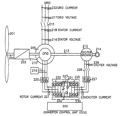
[041 Electric power transmission is one process in the delivery of
electricity to consumers. A power transmission system is often referred to as
a
"grid". Transmission companies must meet the challenge of getting the
maximum reliable capacity from each transmission line. However, due to
system stability considerations, the actual capacity may be less than the
physical limit of the line. Thus, good clean sources of electrical power are
needed to improve system stability.
[05] In most applications, wind turbines generate electric power and
feed current into the electric grid. This may cause deviations of the local
grid
voltage, such as a change of the steady state voltage level, dynamic voltage
variations, flicker, an injection of currents with non-sinusoidal waveforms
(i.e.
harmonics), and the like.
[06] These effects can be undesirable for end-user equipment and other
generators or components connected to the grid, such as transformers. As the
power capacity increases, an evident need arises for improving the power
quality characteristics of the turbine output. The power quality impact of a
wind turbine depends on the technology involved with it. Despite this fact,
wind turbines manufacturers did not consider the power quality as a main
design feature.
[07] Originally, the first wind turbines were designed to work at a fixed
rotational speed. According to this model, the wind turbine's generator is
directly connected to the grid and operates at a determined speed, allowing
very minor speed variations. In the case of an asynchronous generator, only
the slip range of the generator is allowed. The slip being the difference in
the
rotation speed of the rotor as compared to the rotating magnetic field of the
2
CA 02646119 2008-09-16
WO 2007/135573 PCT/IB2007/002680
stator. The generator's slip varies slightly with the amount of generated
power, and it is therefore not entirely constant. Furthermore, these wind
turbines need starting current limitation strategies and reactive energy
compensation elements during normal operation. Wind turbulence produces a
non-desirable torque variation which is directly transmitted to the wind
turbine's drive train and, hence, to the active power fed to the electrical
grid.
[08] A type of wind turbine that keeps the rotational generator speed
proportional to the wind speed, is a variable speed wind turbine. In order to
obtain the maximum efficiency of the wind turbine, the generator rotational
speed adapts to the fluctuating wind speed. This type of wind turbine includes
power electronic converters that are connected to the grid. Due to this kind
of
interface, harmonic emissions from the turbine's power electronic converters
are fed into the grid.
[09] Presently wind turbines of the variable speed type using power
electronic converters have become widespread. Examples of this variable
speed wind turbine are described in U.S. Patent No. 5,083,039, U.S. Patent
No. 5,225,712 or U.S. Published Application 2005/0012339. These turbines,
based on a full converter system, include a generator, a converter on the
generator side, a DC link Bus, and an active converter connected to the grid.
The variable frequency energy of the generator is transferred to the DC link
Bus by the generator side converter, and later transformed to a fixed
frequency
by the grid side active converter. Some disadvantages are common to all full
converter systems. The active switching of the semiconductors of the grid side
converter injects undesirable high frequency harmonics to the grid. To avoid
the problems caused by these harmonics, a number of filters must be installed.
3
CA 02646119 2008-09-16
WO 2007/135573 PCT/IB2007/002680
Furthermore, due to the different impedance values on the grid and previously
existing harmonics, different tuning of the filters is required according to
the
characteristics of the wind farm location.
[10] Another variable speed wind turbine is described in the U.S.
Patent No. 6,137,187. As shown in Figure 1, this wind turbine configuration
includes a doubly fed induction generator (1), a power converter (4)
comprising an active converter on the rotor side (5), a DC Bus (8), and an
active converter on the grid side (7). In this configuration, only a minor
part of
the total power is transferred through the converters (5, 7) to the grid (9).
Power can be delivered to the grid (9) directly by the stator (3), whilst the
rotor (2) can absorb or supply power to the grid (9) via the power converter
(4)
depending on whether the doubly fed induction generator is in subsynchronous
or supersynchronous operation. Variable speed operation of the rotor has the
advantage that many of the faster power variations are not transmitted to the
network but are smoothed by the flywheel action of the rotor. However, the
use of power electronic converters (4) connected to the grid (9) causes
harmonic distortion of the network voltage.
[ I 1] Other documents also describe variable speed wind turbines. For
example, U.S. Patent No. 6,933,625 describes a variable speed system which
includes a doubly fed induction generator, a passive grid side rectifier with
scalar power control and dependent pitch control. In this case, there is an
active converter on the rotor side, a passive grid side rectifier and a
switchable
power dissipating element connected on the DC link Bus. During
supersynchronous operation the energy extracted from the rotor is dissipated
in the switchable power dissipating element, reducing the efficiency of the
4
CA 02646119 2008-09-16
WO 2007/135573 PCT/IB2007/002680
wind turbine; during the operation of the wind turbine in the subsynchronous
mode, the energy is rectified by the passive grid side rectifier which causes
undesirable low frequency harmonics in the grid. Thus, complex attenuation
filters are required. U.S. Patent No. 6,566,764 and U.S. Patent No. 6,856,038
describe variable speed wind turbines having a matrix converter. Both cases
include power electronic converters connected to the grid, which may cause
undesired harmonic voltages.
[12] All the previously mentioned U.S. Patents and other existing
solutions on variable speed wind turbines that include power electronics have
converters connected to the grid. Depending on the technology used on the
converters, there are different ranges of harmonics introduced on the grid
which must be attenuated by using filters, and tuned to the final application
location, making the systems more expensive and less reliable.
[13] In view of these problems in the prior art, there is a need to
provide an improved power solution, which may be applied to variable speed
wind turbines.
[14] Another undesirable problem, especially in the case of weak grids,
is the reactive power consumption during the synchronization of the generator.
For example, a synchronization method is described in the U.S. Patent No
6,600,240. This method starts connecting the generator stator to the grid
while
the power converter is disabled and the rotor has reached a predefined speed.
At this moment, the full magnetizing current is supplied by the grid, which
causes a reactive power consumption. This reactive power consumption is
sometimes not allowed by some new grid compliance regulations. This patent
also describes a disconnection process. The process starts reducing the rotor
CA 02646119 2008-09-16
WO 2007/135573 PCT/IB2007/002680
current and disabling the rotor converter. In this moment, the reactive
magnetizing current is supplied by the grid. To disconnect the generator the
contactor is opened with reactive current, decreasing the operational life of
the
contactor. Accordingly, there is a need to provide a method for
synchronization, connection and disconnection to the grid of the doubly fed
induction generator, which avoids the consumption of reactive power and
increases the lifetime of connecting devices.
[15] Another aspect that determines the power quality injected to the
grid is the control of the generator. One type of control of the generator
side
converter is known as "field orientated control" (FOC). The FOC method is
based on the electrical model and the parameters of the machine. Due to the
dispersion of the machine parameters, the torque can not be accurately
calculated, and additional online adjusting loops are required. Moreover, the
FOC method that is used introduces delays in the flux position identification
when a fault occurs in the grid, making it more difficult to fulfill the new
grid
compliance requirements.
[16] In prior art variable speed wind turbines with DFIG configuration,
although the stator power remains constant, the rotor power is also fed into
the
grid through the power converter. Due to the rotor power ripple, the total
power fed into the grid is also rippled, affecting the output power quality of
the wind turbine.
[17] Variable speed wind turbines, which only use a doubly fed
induction generator, cannot use electric braking. As described above, in this
kind of configuration, power is delivered to the grid directly by the stator,
and
a minor part of the total power is transferred from the rotor to the grid
through
6
CA 02646119 2008-09-16
WO 2007/135573 PCT/IB2007/002680
the converters. When an incidental stop of the wind turbine occurs, for
example during a persistent fault in the grid, the generator's power decreases
sharply. Only fast non-electrical braking, such as blade pitching, can be
applied to stop the wind turbine. This operation mode produces great
mechanical strengths in wind turbine components, which may cause premature
damages. Thus, there exists a need for additional braking to prevent this
mechanical stress.
[18] The use of high voltage DC link transmission (HVDC) in wind
farms is described in Patent No. WO01/25628, which includes a synchronous
generator as the main generation device. Due to the use of synchronous
machines, the output frequency varies with the wind, so especially at low wind
conditions, the ripple content of the output DC voltage becomes high.
Furthermore, the output transformer and rectifier must be oversized because
they must be able to operate at low frequency. Additional details, such as
special construction of the rotor circuitry with low inductance, are mandatory
for the accurate regulation of the output power.
SUMMARY OF THE INVENTION
[19] According to one aspect of an exemplary embodiment of the
present invention, there is provided a variable speed wind turbine with a
doubly fed induction generator, having at least one or more blades, one or
more generators, one or more exciter machines coupled to the drive train, one
or more active power electronic converters joined by a DC link Bus with one
of the AC side connected to the rotor circuit of the doubly fed induction
generator, and the other AC side connected to the exciter machine. The
invention also describes a power control and a pitch regulation.
7
CA 02646119 2008-09-16
WO 2007/135573 PCT/IB2007/002680
[20] According to this aspect of a non-limiting exemplary embodiment
of the invention, power electronics are not connected to the grid. Thus, power
is only delivered to the grid through the stator of the doubly fed induction
generator, avoiding undesired harmonic distortion, and achieving a better
power quality to feed into the utility grid. Moreover, the use of complex
filters
and their tuning according to different locations may be avoided, making the
system more economical and reliable.
[21] Another aspect of an embodiment of the present invention is that
power output remains constant above rated speed avoiding power fluctuations
dependent on= speed changes. Due to the topology of the invention, power is
only delivered to the grid through the stator of the doubly fed induction
generator. Thus, the rotor power ripple is avoided and the output power
quality
of the wind turbine is improved.
[22] Another aspect of an exemplary embodiment of the present
invention describes a variable speed wind turbine that uses Grid Flux
Orientation (GFO) to accurately control the power injected to the grid. An
advantage of this control system is that it does not depend on machine
parameters, which may vary significantly, and theoretical machine models,
avoiding the use of additional adjusting loops and achieving a better power
quality fed into the utility grid.
[23] A further aspect of an exemplary embodiment of the present
invention is that the method for synchronization of the doubly fed induction
generator avoids the consumption of reactive power during the connection and
disconnection to/from the grid, complying with the new grid compliance
8
CA 02646119 2008-09-16
WO 2007/135573 PCT/IB2007/002680
regulations. Moreover, this method may avoid connection current peaks
through connecting devices, increasing the lifetime of such components.
[24] A further aspect of an exemplary embodiment of the present
invention provides a control method to avoid the "wearing" of the collector of
a DC motor when used to drive the pitch movement of the blade and improves
the lubrication of the bearings of the blades.
[25] Another aspect of an exemplary embodiment of the present
invention is that in the case of an incidental stop of the wind turbine,
although
a doubly fed induction generator is used, it is possible to apply electric
braking. In the event of an emergency, such as a persistent grid fault, an
incidental stop of the wind turbine may happen. Then, the exciter machine is
used as generator and power can be transferred from exciter machine to direct
current Bus. Then, the electric brake may be activated and part of the
electric
power is drained in the rheostat of the chopper helping the generator to stop
progressively and avoiding great mechanical strengths in wind turbine
components.
[26] Another aspect of the present invention is that it can be used for
high voltage DC link transmission (HVDC) in variable speed generation
systems.
[27] According to another aspect, due to the topology of the present
invention, the output frequency of the AC voltage may be fixed, allowing a
smaller dimensioning of required rectifiers and transforiners, and reducing
the
ripple content of the DC output voltage under low wind conditions, improving
the output power quality.
9
CA 02646119 2008-09-16
WO 2007/135573 PCT/IB2007/002680
[28] It is to be understood that both the foregoing general description
and the following detailed description are exemplary and explanatory only and
are not restrictive of the invention, as claimed.
BRIEF DESCRIPTION OF THE DRAWINGS
[29] The incorporated drawings constitute part of one or more
embodiments of the invention. However, they should not be taken to limit the
invention to the specific embodiment. The invention and its mode of operation
will be more fully understood from the following detailed description when
taken with the incorporated drawings in which:
[30] Figure 1: Illustrates a conventional variable speed wind turbine
system with doubly fed induction generator and power converters connected to
the grid.
[31] Figure 2: Illustrates one implementation of a circuit diagram for a
variable speed wind turbine having an exciter machine and a power converter
not connected to the grid according to one exemplary embodiment.
[32] Figure 3: Illustrates a block diagram of a power control and a pitch
control for a variable wind speed turbine.
[33] Figure 4: Illustrates a block diagram of one embodiment of the
Optimum Power Tracking Control (OPTC) method.
[34] Figure 5: Illustrates a block diagram of one embodiment of the
GFO and the Doubly Fed Induction Generator's Controller.
[35] Figure 6: Illustrates a block diagram of one embodiment of the
Exciter Machine Controller.
CA 02646119 2008-09-16
WO 2007/135573 PCT/IB2007/002680
[36] Figure 7: Illustrates a flow diagram of one embodiment of the
synchronization, connection and disconnection sequence.
[37] Figure 8: Illustrates a block diagram of one embodiment of the
pitch control system.
[38] Figure 9: Illustrates a block diagram of one embodiment of the
voltage regulation mode used during synchronization.
[39] Figure 10: Illustrates a block diagram of one embodiment of the
HVDC wind turbine with high voltage generator and rectifier.
[40] Figure 11: Illustrates a block diagram of one embodiment of the
HVDC wind turbine with low voltage generator, transformer and rectifiers.
[41] Figure 12: Illustrates a flow diagram of one embodiment of a
method for applying the dynamic electric brake.
DETAILED DESCRIPTION
[42] A variable speed wind turbine according to various exemplary
embodiments is described below. Several drawings will be referenced only as
illustration for the better understanding of the description. Furthermore, the
same reference numbers will be used along the description referring to the
same or like parts.
Overview
[43] Generally, the variable speed wind turbine generator according to
various exemplary embodiments of the present invention channels the
electrical power generated by the rotor during super synchronous operation of
the doubly fed induction generator, to an exciter machine. The exciter
machine then converts this electrical energy back into mechanical rotation
11
CA 02646119 2008-09-16
WO 2007/135573 PCT/IB2007/002680
energy, which can then be used to further increase the electrical power
generated by the stator that is delivered to the grid. Electrical power is
only
delivered to the grid by the stator of the DFIG avoiding the delivery of power
to the grid through power converters. Thus, the quality of the electrical
power
supplied to the grid is improved.
[44] Additionally, during sub synchronous operation, when the rotor,
instead of generating electrical power, requires an electrical power source, a
portion of the rotational energy generated by the wind is used by the exciter
machine to generate the electrical power required by the rotor.
[45] The variable speed wind turbine generator system is broadly
shown in Figure 2. In this embodiment, the variable speed system comprises
one or more rotor blades (201), a rotor hub which is connected to a drive
train.
The drive train mainly comprises a turbine shaft (202), a gearbox (203), and a
doubly fed induction generator (205). The stator of the doubly fed induction
generator (210) can be connected to the grid by using one or more contactors
(215). The system also comprises an exciter machine (212) such as an
asynchronous machine, a DC machine, a synchronous (e.g. permanent
magnet) machine, or a reversible electrical machine that functions as either a
motor or a generator, which is mechanically coupled to the drive train and two
active electronic power converters (222, 225) joined by a DC link Bus (224)
(i.e. a back to back converter) with one of the AC side connected to the rotor
circuit of the doubly fed induction generator and the other AC side connected
to the exciter machine (212). The active power converter (225) which
regulates the exciter machine is not connected to the grid, such that the
active
power converter is isolated from the grid. Alternatively, a cycloconverter, a
12
CA 02646119 2008-09-16
WO 2007/135573 PCT/IB2007/002680
matrix converter or any other kind of bi-directional converter may be
connected instead of a back to back converter. The system could also comprise
an electric brake circuit (231), such a DC chopper, connected to the DC Bus.
The converter control unit (CCU) (200) carries out the power regulation of the
doubly fed induction generator and the exciter machine. The system comprises
filters such a dV/dt filter (220) which is connected to the rotor circuit of
the
doubly fed induction generator in order to protect it against abrupt voltage
variations produced by the active switches of the power electronic converter.
Furthermore, a dV/dt filter (227) is connected between the electronic power
converter and the exciter machine. In one embodiment, a protection module
(219) against grid faults is connected to the rotor of the doubly fed
induction
generator.
[46] The variable speed wind turbine generator system described in this
embodiment can work below the synchronous speed (i.e. subsynchronous) and
above the synchronous speed (i.e. supersynchronous). During the
subsynchronous operation, power flows from the exciter machine (212) to the
rotor (211) of the doubly fed induction generator (205), so the exciter
machine
(212) acts as a generator. On the other hand, during the supersynchronous
operation, the power flows from the rotor (211) of the doubly fed induction
generator (205) to the exciter machine (212), therefore the exciter machine
acts as a motor. The power balance during the whole range speed is such that
power generated/consumed in the exciter machine (212) is
consumed/generated in the rotor (211) of the doubly fed induction machine,
except for the losses in the different elements.
13
CA 02646119 2008-09-16
WO 2007/135573 PCT/IB2007/002680
[471 Due to the topology of the variable speed wind turbine generator
system described, power is only delivered to the grid through the stator (210)
of the doubly fed induction generator (205). There is no electronic power
converter connected to the grid. Consequently, undesired harmonic distortion
is avoided and a better power quality to feed into the utility grid is
achieved.
Moreover, the use of complex filters and their tuning demands according to
different locations is also avoided, making the system more economical and
reliable.
[48] This topology also allows the use of an electric brake in a doubly
fed induction generator configuration. In case of a wind turbine emergency
stop due, for example, to a full blackout of the grid, the stator is
disconnected
and power produced by the generator can not be fed into the grid. However,
the exciter machine (212) can be used as generator, and hence power can be
transferred from the exciter machine (212) to the direct current Bus (224).
Therefore, part of the electric power is drained in the rheostat of the
chopper.
Finally, mechanical or aerodynamic brake, such as blade pitching, is applied
to
stop the wind turbine. This embodiment of the present invention allows the
generator to apply electric brake in a DFIG configuration, helping the wind
turbine to stop and avoiding great mechanical strengths in wind turbine
components, which may cause premature damage.
[49] The variable speed wind turbine control system, as shown in
Figure 3, comprises a general controller (302), power controllers and a pitch
regulator. The power set point is calculated by the Optimum Power Tracking
Controller (OPTC) (303) based on measured wind speed. This set point is sent
to the General Controller (302) and hence to DFIG Controller (300). The
14
CA 02646119 2008-09-16
WO 2007/135573 PCT/IB2007/002680
power delivered to the grid by the doubly fed induction generator (205) is
controlled by the DFIG Controller (300) making an effective regulation of the
total active power and the total reactive power through the active electronic
power converter (222). The power electronic control of the doubly fed
induction generator (205) is based on the grid flux orientation (GFO). The
exciter machine (212) is regulated by an active electronic power converter
(225) and controlled by the Exciter Controller (301). The power transferred
to/from the exciter machine (212) is controlled by the active electronic power
converter, using as main regulation variable the DC Bus voltage level,
measured with the DC Bus voltage sensor (223).
[50] The variable speed wind turbine control system also comprises a
pitch control system, which is based on the limitation of the demanded power
to the exciter. The Exciter Based Pitch Controller (EBPC) (304) regulates the
pitch position of the blades in order to limit aerodynamic power. The EBPC
(304) also provides pitch angle set point for OPTC (303) from exciter's power
deviation and by measuring the speed and position of pitch motor (305). In
addition, EBPC (304) comprises a Collector Anti-Wearing & Lubrication
System (CAWLS) in order to protect the collector of the DC machine used for
the pitch movement and improve lubrication of blades bearings.
[511 The topology of the present invention is also suitable for high
voltage DC link transmission (HVDC) in variable speed generation systems.
As shown in Figure 10and Figure 11, the DC output can be produced by using
a high voltage generator with a rectifier (1001), as shown in Figure 10, or
with
a low voltage generator and an additional transformer (1101) with one or more
secondaries, as shown in Figure 11, wherein each secondary is rectified and
all
CA 02646119 2008-09-16
WO 2007/135573 PCT/IB2007/002680
of such rectifiers are connected in series or parallel way. Additional
connecting devices (1002) and protection devices (1003) are required.
[52] Due to the topology of the present invention, the output frequency
of the AC voltage can be fixed, allowing a smaller dimensioning of required
rectifiers and transformers and reducing the ripple content of the DC output
voltage under low wind conditions, improving the output power quality.
[53] Furthermore, once the wind turbine starts rotating, all the auxiliary
systems can be fed by the exciter machine (212), notwithstanding the
operation of the main generator, reducing the size of the uninterruptible
power
supply or of the HVDC to AC converter.
[54] Note that, although grid applications are described, it would be
apparent to one skilled in the art that the present invention may also be used
for other applications such as stand-alone power systems or any variable speed
energy generation system. For example, such other variable speed energy
generation systems may include power systems based on wave and tidal
energy, geothermal energy, solar energy applications, hydroelectric energy,
internal combustion engines, etc.
Optimum Power Tracking Controller (OPTC)
[55] The Optimum Power Tracking Controller (OPTC) (303) adjusts
the power reference for the power control loop, performed by DFIG Controller
(300), in order to control generator power. This reference is based on
measured wind speed as the main regulation variable.
[56] According to this embodiment, a variable speed system wherein a
tracking of optimum power coefficient (CP) may be carried out within an
operational speed range. This range is determined by a lower speed limit (wo)
16
CA 02646119 2008-09-16
WO 2007/135573 PCT/IB2007/002680
and an upper speed limit (wl) and their correspondent lower power limit and
upper power limit (Po and P, respectively).
[57] Figure 4 illustrates a block diagram of one embodiment for the
Optimum Power Tracking Controller (OPTC). The main input of OPTC is the
wind speed (u), which is measured by means of one or more anemometers. In
one embodiment, this measurement is filtered (401) to avoid undesired
frequencies to be amplified through the control system and so that a smooth
signal is operated.
[58] OPTC calculates a correspondent power value for each particular
wind speed (402). This relationship is determined from the overall
characteristics of the wind turbine, the rotor head mainly, and its points
correspond to the maximum aerodynamic efficiency. Thus, CP is maximised to
achieve maximum power output. Obtained power value is input to a power
range limiter (403). This implementation comprises the main loop.
[59] An auxiliary correction (405) of the main loop is applied to the
obtained value to improve the responsiveness of the optimised Cp tracking.
Doubly fed induction generator optimum speed is worked out (406) from
measured and filtered wind speed signal. The rotor optimum speed (on the
low-speed shaft) is the result of dividing the product of optimal tip speed
ratio
(k) and wind speed (u) by the rotor plane radius (R). Doubly fed induction
generator rotational speed is calculated by multiplying this value by the
gearbox ratio. Obtained speed value is input to a speed range limiter (407).
The output of this block is compared (408) with a pitch corrected speed (PCS),
calculated in the Pitch Adapted Speed Block (PASB) (410).
17
CA 02646119 2008-09-16
WO 2007/135573 PCT/IB2007/002680
[60] Pitch angle reference, minimum pitch angle and measured
rotational speed are input to PASB. A gain (413) is applied to the difference
between filtered pitch angle set point ((3,,r) and minimum pitch angle
((3min)=
For the coupling, this term is initialised to zero, being (3,~r =p min.
Measured
rotational speed (W) is added to calculate said corrected speed.
[61] After such correction by PASB (408), a gain (409) is applied to
the obtained error providing a OP to be added to the previously calculated
power set point.
[62] Once the obtained power set point has been corrected (404), the
value is input to a power range limiter (415) to ensure that this power
reference is within Po and P, thresholds. The obtained reference is the power
set point (SP_P).
[63] A rotational speed surveillance (417) is finally applied to this
power set point. In case PCS is lower than wo (419) a gain or a different
controller (420) is applied to such speed difference providing a-OP. On the
other hand, if PCS is higher than coi (422), a gain (423) is applied to
calculated
error providing a AP, proportional to the speed difference at the input.
[64] Therefore, above detailed correction is applied to the power set
point SP P, which, in addition, is input to a power range limiter (424) in
order
to ensure that calculated set point does not exceed rated power. Hence, the
output of OPTC is the effective power reference SP_Pef to be transmitted to
General Controller (302) and hence to DFIG Controller (300) in order to
control the doubly fed induction generator power.
[65] Due to Optimum Power Tracking Controller, the output power
quality when generator speeds are equal or greater than the generator speed at
18
CA 02646119 2008-09-16
WO 2007/135573 PCT/IB2007/002680
which rated power occurs is improved. In the prior art variable speed wind
turbines with a DFIG configuration, although the stator power remains
constant, the rotor power is also fed to the grid through the power converter.
Due to the rotor power ripple, the total power fed into the grid is also
rippled,
affecting the output power quality of the wind turbine. Within the present
invention, by using an exciter machine and a power converter not connected to
the grid, power is only delivered to the grid through the stator of the doubly
fed induction generator, avoiding ripple and improving the output power
quality of the wind turbine.
Doubly Fed Induction Generator Controller
[66] The DFIG's stator active power and reactive power control is
made by the Doubly Fed Induction Generator's Controller (300). This
controller offers a good regulation performance and control of the total power
delivered to the grid. This control is based, as it is explained in further
detail
below, on different regulation loops, totally independent from the electrical
parameters of the machine by using the Grid Flux Orientation (GFO). By
measuring with a high accuracy the different magnitudes to be regulated, the
total power delivered to the grid by the stator (210) of the doubly fed
induction
generator 205 is perfectly controlled, achieving a high quality energy.
[67] The Doubly Fed Induction Generator's Controller (300),
illustrated in Figure 5, is based on the Grid Flux Orientation (GFO) control
and four regulation loops: Two current loops (Irq, rotor current loop (509),
and
Ird, rotor current loop (510)) and two power loops (Ps, Stator active power
loop (505), and Qs, Stator reactive power loop (506)).
19
CA 02646119 2008-09-16
WO 2007/135573 PCT/IB2007/002680
[68] In this exemplary embodiment of present invention, the controller
is going to regulate the DFIG's stator active power and reactive power by
regulating the rotor currents (Av Ird and Av Irq) and, consequently, the total
power delivered to the grid. The power controller operates with the current
and voltage magnitudes referred to a two axes rotating system (d,q), so the
different current and voltage measurements carried out by the system are
transformed (514, 517) to the referred rotating (d,q) system.
[69] In one embodiment, by controlling the Av_Ird (rotor current
referred to as the `d' axis), the magnetising level of the doubly fed
induction
generator (205) is fixed, so the reactive power flow direction in the machine
is
established. Furthermore, the doubly fed induction generator (205) may work
as an inductive system, consuming reactive power, or may work as a
capacitive system, generating reactive power. In this embodiment, the control
of the Av_Ird is carried out totally independent on the control of the Av_Irq
(rotor current referred to `q' axis). In another embodiment, by controlling
the
Av_Irq, the active power generated by the doubly fed induction generator and
delivered to the grid is perfectly controlled.
[70] Accordingly, the DFIG's stator active power loop (507) regulates
the stator power (Av_Ps), by receiving a stator power set point (Sp_Pef) from
the OPTC (303) and, hence, (Sp_Ps) from the General Controller (302). This
loop may be based on a PI controller or a different controller with a more
complex structure. The DFIG's stator active power calculation is described in
further detail below. The PI controller (507) output is the rotor current set
point (Sp_Irq). The Irq rotor current loop (511) regulates the Av_Irq current
with this aforementioned set point. This Irq current loop may be based on a PI
CA 02646119 2008-09-16
WO 2007/135573 PCT/IB2007/002680
controller or a different controller with a more complex structure. The
regulator ouput is the Urq rotor voltage set point (Sp_Urq).
[71] Furthermore, the DFIG's stator reactive power loop (508)
regulates the stator reactive power (Av Qs), receiving a stator reactive power
set point (Sp_Qs) from the General Controller (302). This Sp_Qs may be
based on a fixed value, SCADA settings or the like. This reactive power loop
may be based on a PI controller or a different controller with a more complex
structure. The stator reactive power calculation is described in further
detail
below. The PI controller (508) output is the Ird rotor current set point
(Sp_Ird). The Ird rotor current loop (512) regulates the Av Ird current with
this aforementioned set point. This Ird current loop may be based on a PI
controller or a different controller with a more complex structure. The
regulator output is the Urd rotor voltage set point (Sp_Urd). In one
embodiment, this method allows magnetizing of the doubly fed induction
generator from the rotor, avoiding reactive power consumption from the grid.
Furthermore, controlling the doubly fed induction generator magnetising level,
and measuring the grid and stator voltages the system is continuously
synchronised to the grid, regarding at every moment the amplitude, the
frequency and the angle of the stator voltages generated by the doubly fed
induction generator (205). Connection and disconnection systems will be
explained below in further detail.
[72] In one embodiment, the AV_Irq and Av_Ird rotor currents are
calculated referring the three rotor currents measurement (Ir L1, Ir L2, Ir
L3)
(121), to a two axes rotational system with a rotational angle ( -s) where
is
the grid angle, calculated from the measurement of the three grid voltages
21
CA 02646119 2008-09-16
WO 2007/135573 PCT/IB2007/002680
(Vg_L1, Vg_L2, Vg_L3) (217), and c is the rotor angle measured with the
position and speed sensor (214).
[73] The Av_Ps and Av_Qs are calculated using Id, Iq, Vd, Vq:
Av Ps= ~(VsdxIsd+Vsqxlsq) Eq. 1
Av_Qs= 2(Vsqx lsq-Vsdx lsd) Eq. 2
[74] where Vsd, Vsq, Isd, Isq are obtained by measuring the three
stator voltages (V_Ll, V L2, V_L3) (216) and the three stator currents (I_L1,
I L2, I_L3) (118), and referring these voltages and currents to a two axes
rotational system, using the rotational angle.
[75] Both current regulator outputs, Sp_Urd and Sp_Urq, are
transformed into a fixed system, using the rotating angle ( -E), obtaining the
three voltage references to be imposed in the rotor (211) of the doubly fed
induction generator (205). Block 414 shows the transformation of the rotor
voltages, from a two axes rotational system to a three phase fixed system. In
one embodiment, these rotor voltages may be used as reference to a module
for generating the triggering of the active switches of the power electronic
converter (222). Block 415 shows the module where different PWM
techniques may be implemented.
[76] According to this embodiment, an electronic power control system
based on two power loops and two current loops, independent on the machine
electrical parameters, avoids the effects of the electrical parameter
dispersion
or the theoretical modelling errors in the power regulation. Errors caused by
22
CA 02646119 2008-09-16
WO 2007/135573 PCT/IB2007/002680
the electrical parameters change because of temperature oscillations or
saturation effects due to the non linearity and are avoided by this method.
Thus, a very good quality energy generation is obtained, fulfilling and
improving the requirements of the different normative. Only different
measurements are necessary to make the regulation (I_L1, I_L2, I L3, V L1,
V L2, _L3, Ir L1, Ir L2, Ir L3, c, co). In one embodiment, the reactive power
regulation could be made independent of the active power regulation.
Exciter Controller
[77] In one exemplary embodiment, the variable speed system
comprises a doubly fed induction generator (205) wherein the rotor (211) is
connected to an electronic power converter (222). This electronic power
converter is coupled through a DC Bus system (224) to a second electronic
power converter (225). In one embodiment, this frequency converter (power
converter) (225) is connected by contactor (228) to the exciter machine (212).
The exciter machine, such as an asynchronous machine, a DC machine or a
synchronous (e.g. permanent magnet) machine or a reversible electrical
machine, is mechanically coupled to the drive train.
[78] Depending on the rotor speed, the power demanded to the exciter
machine may be positive or negative, according to the direction of the rotor
energy flow. During the subsynchronous operation, i.e. below the synchronous
speed, power flows from the exciter machine (212) to the rotor (211) of the
doubly fed induction generator (205), so that the exciter machine (212) acts
as
a generator. During the supersynchronous operation, i.e. above the
synchronous speed, the power flows from the rotor (211) of the doubly fed
induction generator (205) to the exciter machine (212), therefore the exciter
23
CA 02646119 2008-09-16
WO 2007/135573 PCT/IB2007/002680
machine (212) acts as a motor. The power balance during the whole range
speed is such that power generated/consumed in the exciter machine is
consumed/generated in the rotor of the doubly fed induction machine, except
for the losses in the different elements.
[79] In this embodiment of the present invention, the exciter machine
(212) is regulated by the electronic power converter (225) and controlled by
the Exciter Controller (301). The control system of the exciter machine (212)
is described below referring to the exciter machine as a permanent magnet
machine. It should be apparent to one skilled in the art that different type
of
machines may be used as an exciter machine (212), so the exciter controller
may modified accordingly.
[80] Power transferred to/from the exciter machine (212) is controlled
by the electronic power converter (225), using as main regulation variable the
DC Bus voltage level, Av Ubus. Figure 6 describes one embodiment of the
exciter machine regulation. The Converter Control Unit (200) fixes a DC Bus
set point voltage Sp_Ubus (605) which may be variable or static. By
measuring the DC Bus voltage , the DC Bus voltage set point is regulated by a
PI controller (607) or a different controller with a more complex structure.
This controller establishes the active power to be transfer between the
permanent magnet exciter machine (212) and the DC link Bus (224) in order
to keep the DC Bus voltage at the value fixed by the Converter Control Unit
(CCU). This active power is determined by the Sp_IEq. In one embodiment
this Sp_IEq is calculated from two terms:
Sp_IEq = Bus voltage regulator (607) output + Decoupling &
switching on compensation (608) output Eq. 3
24
CA 02646119 2008-09-16
WO 2007/135573 PCT/IB2007/002680
[81] where the first term responds to possible Bus oscillations and the
second term, Iz, is a feed forward term which represents the estimated current
circulating through the Bus. With this type of structure it is possible to
achieve
high dynamic power response of the permanent magnet machine. In one
embodiment, the Bus current estimation term does not exist, so the Bus
voltage regulator (607) is taking charge of generating the effective Sp_IEq
demanded to the permanent magnet exciter machine.
[82] In this embodiment, the Sp_IEq is regulated by a PI controller
(613) or a different controller with a more complex structure, using the
Av_IEq which represents the exciter machine active current referred to a two
axes rotating system. In one embodiment, a permanent magnet machine may
be used, so a field weakening module is required to be able to reduce the
machine flux and to have a better power regulation at high speed. In a
permanent magnet machine the stator voltage depends on the rotor speed and
on the machine magnet flux. Consequently, above a rotor speed is necessary to
reduce the stator voltage by reducing the flux on the machine.
[83] In one embodiment a field weakening system is implemented,
establishing a reactive current set point, Sp_IEd (618) which is going to be
demanded to the permanent magnet exciter machine (212). In this way,
independent on the rotor speed, the voltage generated by the permanent
magnet is controlled and placed in the band range regulation capability of.the
electronic power converter (225). The Sp_IEd (618) is regulated by a PI
controller (614) or a different controller with a more complex structure,
using
the Av_IEd which represents the exciter machine reactive current referred to
as a two axes rotating system.
CA 02646119 2008-09-16
WO 2007/135573 PCT/IB2007/002680
[84] In one embodiment, the Sp_lEd fixes the magnetising level of the
machine, and its voltage level. The Sp_IEq fixes the active power injected or
demanded to permanent magnet machine.
[85] In one embodiment, two or three exciter machine phase currents
may be measured (IExc L 1, IExc_L2, IExc L3) in order to calculate Av IEd
and Av_IEq. The three currents are initially transformed (601) to a two axes
static system so IE_sx and IE_sy are obtained. Secondly, these two currents
are referred (603) to a two axes system which rotates with the permanent
magnet machine total flux, obtaining Av_IEd and Av_IEq. This current
transformation is made by using the angle Exc, obtained from the three or
two exciter machine phase voltages which may be measured or estimated
(VExc Ll, VExc_L2, VExc_L2). Blocks 602 and 604 show how the
permanent magnet machine flux and voltage absolute values are obtained.
[86] In one embodiment an Effective Voltage calculation module (615)
is required because the voltage to be generated by the electronic power
converter (225) must rely on the flux interaction in the permanent magnet
machine due to the effect of current circulation. So, voltage set points
Sp_UErd and Sp_UErq are calculated (615) from the two PI current regulators
(613, 614) outputs and from Av_IEd, Av_IEq and IVEI.
[87] The two voltage set points, Sp_UErd and SP_Uerq, are
transformed (616) into a three axes static system, using the rotating angle
Exc. Thus, the voltage references Sp_UE_Rx and Sp_UE_Ry are obtained to
be imposed in the stator of the permanent magnet exciter machine (212). In
one embodiment, these voltage set points may be used as references to a
module for generating the triggering of the active switches of the power
26
CA 02646119 2008-09-16
WO 2007/135573 PCT/IB2007/002680
electronic converter (225). Block 617 shows the module where different PWM
techniques may be implemented. In one embodiment, a dV/dt filter or any
other kind of filter (227) may be installed between the electronic power
converter (225) and the exciter machine (212).
[88] In one embodiment, the exciter machine (212) may be used to
supply energy to different elements of the wind turbine, using this machine as
an Auxiliary Power Supply. Grid disturbances or faults do not affect the power
electronic converter (225). Consequently, the exciter power regulation is not
affected.
Dynamic Electric Brake
[89] According to another embodiment, a Dynamic Electric Brake
(DEB) is provided that allows the wind turbine to apply an electric brake to
stop the generator. Therefore, mechanical strengths in wind turbine
components, which may cause premature damages, may be avoided.
[90] The variable speed wind turbine of present invention comprises a
doubly fed induction generator (205) where the rotor (211) is connected to an
electronic power converter (222). This electronic power converter (222) is
coupled through a DC Bus system (224) to a second electronic power
converter (225). This frequency converter (electronic power converter (225))
is connected to the exciter machine (212). The exciter machine, such as an
asynchronous machine, a DC machine, a synchronous (e.g. permanent
magnet) machine or a reversible electrical machine, is mechanically coupled
to the drive train. The system also comprises an electric brake circuit (231),
such a DC chopper, connected to the DC Bus.
27
CA 02646119 2008-09-16
WO 2007/135573 PCT/IB2007/002680
[91] Within prior art DFIG topologies, if the stator power of the DFIG
decreases abruptly due to a grid fault or a disconnection from the grid, the
machine tends to speed up. In the case of a wind turbine operating at rated
power, the machine may suffer an overspeed. Usually, it is not possible to use
electric brake in such moment, because the DFIG's stator power and,
furthermore, the DFIG's rotor power may be too low. However, due to the
topology of the present invention, the exciter machine power can be used to
drive an electric brake. In this case, the exciter machine will be used as
generator and, hence, power can be transferred from the exciter machine to the
direct current Bus. Thus, part of the electric power is drained in the
rheostat of
the chopper connected to the DC Bus avoiding overspeed of the generator. In
such a way, the wind turbine braking does not solely depend on the
mechanical brake. In one embodiment, an electric brake may be used together
with mechanical brake, allowing the wind turbine to brake progressively,
minimizing mechanical strengths, peak torque loads and undesired
accelerations. For instance, the electric brake may be applied until
mechanical
or aerodynamic brake is able to take the control of the turbine.
[92] Furthermore, the exciter machine and the DFIG rotor circuitry
may be used in tandem with an electric brake circuit to function as an
electric
brake to stop or slow the rotation of the generator. In such a case, the
braking
is accomplished as follows: when the brake is activated, the rheostat is
switched on, and the electrical power flows to the rheostat. Said electrical
power could flow from the rotor circuit of the DFIG and/or from the exciter
machine, according to the power capabilities of each. This process does not
depend on the sub-synchronous or super-synchronous operation mode.
28
CA 02646119 2008-09-16
WO 2007/135573 PCT/IB2007/002680
[93] While on super-synchronous operation mode the whole braking
power is needed, at sub-synchronous mode the wind turbine is working at low
speeds and only a minor part of braking power is needed.
[94] Another application of the Dynamic Electric Brake is when
operating at high wind speeds. If a wind gust occurs when the machine is
already operating near maximum speed, is necessary to brake the machine to
avoid stopping due to overspeed.
[95] Within prior art DFIG topologies, it is possible to increase the
output power from the stator until the pitch of the blades is modified to slow
the wind turbine. This operation system reduces the quality of the output
power, due to the peaks caused by the wind gust.
[96] Due to the topology of the present invention, it is possible to
maintain the stator output power constant while activating the Dynamic
Electric Brake; by this way, the quality of the output power remains high, and
the speed is reduced until the control of the wind turbine is taken with the
pitch of the blades. As the Power of the Dynamic Electric Brake can be
controlled in a very fast way, accurate control to avoid overspeed can be
performed.
[97] As a result, due to the exciter machine (212), braking power is
always available. Depending on the exciter power, the exciter converter
power, and the rheostat value of the chopper, braking power could reach, in an
embodiment, 30% of generator's rated power.
[98] Thus, there is also a maximum braking power (Pb_MAX)
continuously available:
Pb MAX - `=DC busl2/Rbreke Eq. 4
29
CA 02646119 2008-09-16
WO 2007/135573 PCT/IB2007/002680
wherein VDC bõ$ is the actual value of DC Bus voltage (Av_UbõS)
[99] Braking power may be controlled in such a way that when wind
turbine is working at low speeds only a minor part of braking power is needed.
However, if wind turbine generator is above rated speed it may be necessary to
use the whole braking available power. Thus, a set point of braking power
(SP Pb) is worked out depending mainly on measurements of wind speed and
generator speed.
[100] In order to control the necessary braking power accurately, a
modulation factor (fMOD) is calculated. This modulation factor is applied to
the
maximum braking power available in each moment (Pb_MAx) to obtain the
SP Pb.
SP_Pb = Pb_MAx = fMOD Eq. 5
fMOD = SP_Pb - ( Rbrakc / (AV-Ubus)2 ) Eq. 6
[101] The modulation factor allows an accurate control of the braking
power. A progressive electric braking is possible to apply. For example, in an
emergency stop of the wind turbine, at the beginning, the whole braking power
is needed. Once mechanical braking, such as blade pitching, is activated, it
is
possible to progressively decrease the electric braking.
[102] The Dynamic Electric Brake, in this exemplary embodiment, is
composed of a rheostat (resistor, set of resistors or whatever dissipative
element) activated by an electronically controllable switch (e.g. an IGBT).
Anti-parallel diodes may be also used. DEB is not strictly limited to the
CA 02646119 2008-09-16
WO 2007/135573 PCT/IB2007/002680
embodiment which has been described. Thus the braking chopper may
comprise elements different from those indicated above.
[103] The Dynamic Electric Brake may be activated in response to
various operating parameters. In one embodiment, the speed of the shaft 213
or the turbine shaft (202) may used to activate braking. This speed may be
determined by the position and speed sensor (214) and may be used to activate
braking when exceeding a threshold. Additionally, acceleration or the change
in speed with respect to time may used as an activator. In this case, the
change
in speed over time may be measured by the position and speed sensor (214) to
sense any unusual acceleration. If the acceleration exceeds a threshold, the
braking may then be activated. Additionally, many different braking sensing
conditions are contemplated in this exemplary embodiment. Accordingly, the
activation of the electric brake may depend on various braking conditions
based on the exciter shaft speed, the exciter shaft acceleration, the DFIG
rotor
speed, the DFIG acceleration, the DFIG rotor frequency and sequence, the rate
of change of the DFIG rotor frequency and sequence, the exciter frequency,
the rate of change of the exciter frequency, the exciter voltage or the rate
of
change of the exciter voltage.
[104] The operating power, currents and voltages may also be used to
activate the Dynamic Electric Brake. For example, if the rotor (211) currents
or exciter machine (212) currents exceed a threshold, the braking may be
activated. Likewise, the rotor (211) and exciter (212) voltages may also
indicate some sort of operational anomaly. If such an anomaly is detected, the
braking may be activated. Thus, the brake may be activated when currents
and voltages of the rotor (211) or exciter (212) exceed threshold values.
31
CA 02646119 2008-09-16
WO 2007/135573 PCT/IB2007/002680
Likewise, the frequency of the exciter (212) or rotor (211) currents and
voltages may also be used to activate the brake as they may be indicative of
excessive speed or some other sort of equipment failure.
[105] Accordingly, the electric brake may be activated using the method
illustrated in Figure 12 as follows. First, a braking condition is sensed
(operation 1200). Then, this breaking condition is evaluated to determine if
it
exceeds a threshold value, for example, an excessive current, speed, voltage
or
an excessive rate of change of the current, speed or voltage is compared to
some threshold value indicative that braking may need to be applied
(operation 1201). Based on the braking condition and the threshold value
exceeded, the braking power is calculated in operation 1202. After the
braking power is calculated, the dynamic electric brake may be activated
(operation 1203). The power from the activated dynamic brake is drained in a
dissipative element in operation 1204.
[106] With regard to detecting unusual or large accelerations of the
generator, the change in voltage and current with respect to time, as well as
the
change of the frequency of these parameters over time, may be used to
indicate an unusual acceleration. Thus, if such an acceleration is detected,
the
braking may be activated.
Connection (Enable) Sequence
[107] A connection sequence is provided according to another
embodiment. This embodiment comprises a doubly fed induction generator
(DFIG) (205) coupled to an exciter machine (212) with no power electronic
converter connected to the grid and a connection sequence that allows
connection of the doubly fed induction generator to the grid with no
32
CA 02646119 2008-09-16
WO 2007/135573 PCT/IB2007/002680
consumption of reactive energy and no connection current peaks through
contactor (215), thus, increasing the lifetime of the contactor (215). Figure
7
shows the connection sequence. It would be apparent to one skilled in the art
that the techniques described here can also be applied if a main circuit
breaker
or any other switch, instead of contactor is used to couple the generator to
the
grid.
[108] During normal operation Mode, the turbine is continuously
orienting towards the wind with the use of the yaw motors. When the
measured average wind speed is greater than a threshold (in one embodiment
2,5 metres per second), if all the rest of required conditions are fulfilled,
the
blades are moved by the pitch motor to a position that allows the main rotor
to
start rotating.
[109] In one embodiment, the initial conditions must be fulfilled before
starting the connection sequence (701). These conditions involve the rotor
speed, the state of the rotor contactor (228) and any other previous
conditions
to start the sequence. In one embodiment, once these conditions are fulfilled
the rotor speed must go up to NI (in one embodiment, with a 1800rpm/60Hz
synchronous speed DFIG, the N1 value might be 1170rpm) . Once this rotor
speed is reached, the exciter side electronic power converter (225) is
activated
in order to regulate the DC Bus voltage level, corresponding to state 702.
[110] In one embodiment, once the DC Bus has reached the VBUSI
level, the rotor speed must go up to N2>=N1 (in one embodiment, with a
1800rpm/60Hz synchronous speed DFIG, the N2 value might be 1260rpm,
and the VBUS1 level, with 1700V IGBT, might be 1050V) . The DFIG side
electronic power converter (222) is then switched on (703) in order that
33
CA 02646119 2008-09-16
WO 2007/135573 PCT/IB2007/002680
voltage through contactor (215) comes near 0; This is accomplished by
magnetizing the doubly fed induction generator (205) through the rotor (211)
with the electronic power converter (222), in a way that voltage value,
sequence, frequency and other variables are equal in both sides of the
contactor (215). When the conditions of voltage amplitude, voltage frequency,
voltage angle/delay and some other conditions are fulfilled, the contactor
(215) is closed (704) and stator current is near 0. There is no consumption of
energy from the grid by the doubly fed induction generator (205) , and
possible perturbations on the grid are avoided.
[111] Once this sequence has been fulfilled, power control is activated
(705). To allow a smooth connection to the grid, the active power set point
from the OPTC, and the reactive power set point from the main controller are
ramped up during the initial moments.
[112] During all the connection sequence, the status of all the involved
elements is monitored in such a way that if an error is detected, the sequence
is
resumed and an alarm is generated. Depending on the type of alarm, the
sequence can start a predetennined time later, or if the error is important,
one
emergency mode is activated in the wind turbine which requires human
intervention to exit that mode.
[113] The control system used during state 703 for synchronization is
described in figure 9. A stator voltage regulation is performed. The stator
voltage and the grid voltage are the inputs to the stator voltage regulator
(903
and 904), and the output of this regulator is part of a rotor current set
point in
axis d. A current term proportional to the magnetizing current of the
generator
is added to the output of the voltage regulator as a feed-forward element.
Such
34
CA 02646119 2008-09-16
WO 2007/135573 PCT/IB2007/002680
current feed-forward is calculated according to the measured grid voltage,
measured grid frequency and to a K constant that depends on the electrical
parameters of the generator. With the addition of this feed-forward term
within
block 905, the synchronization process is sped up. The sum of both terms,
which is the output of block 905, is the rotor current set point in the "d"
axis.
During all the synchronization process, the set point of rotor current in the
"q"
axis is equal to 0. Both current set points (in the "d" axis and the "q" axis)
are
the inputs to a current regulation block (906), wherein they are controlled
with
PI regulators. The angle used for the conversion of a two axis system ("d" and
"q") into a 3 phase system in block 906, is calculated on the basis of the
grid
angle and the mechanical angle in block 907.
Disconnection (Disable) Sequence
[114] A disconnection sequence is provided according to another
embodiment of the present invention. This embodiment comprises a doubly
fed induction generator (DFIG) (205) coupled to an exciter machine (212)
with no power electronic converter connected to the grid and a disconnection
sequence that allows disconnection of the doubly fed induction generator
(205) from the grid without any perturbation related to over-currents or over-
voltages on the different elements of the system. Due to the opening of the
contactor (215) in near 0 current, the lifetime of this contactor is increased
and
maintenance operations are reduced. It also allows a lower rating of the
contactor for the same application, compared with other disconnection
sequences.
[115] In normal operation of the wind turbine, this sequence is usually
reached because of absence of wind conditions, but it can be also reached in
CA 02646119 2008-09-16
WO 2007/135573 PCT/IB2007/002680
case of excessive wind, local human request, remote Supervisory Control and
Data Acquisition (SCADA) request, a fault in any subsystem of the wind
turbine or any other reason.
[116] In one embodiment, the stator power and stator current must be
decreased with a ramp in order to have no current in the generator's stator
(710). The ramp down time is optimized according to the reason of the
disconnection sequence request. In order to avoid unnecessary mechanical
stress in the wind turbine, the ramp down time is the maximum that allows a
safe operation of the wind turbine. It is evident that ramp down time
requirements are not the same for every situation.
[117] Once that state (710) has been fulfilled the main contactor (215) is
opened, reaching (711) state. As Active and Reactive Power Set Points are 0
prior to opening the contactor (215), the DFIG Controller (300) is injecting
the
magnetizing current to have the DFIG stator grid connected but without
current, so that the opening of the contactor is made with near 0 current,
extending the lifetime of the contactor (115).
[118] When the (711) state is fulfilled the rotor electronic power
converter (222) is disabled, corresponding to the (712) state. When the rotor
electronic power converter is disabled, the energy stored in the inductive
circuits of the doubly fed induction generator is transferred to the DC link.
Exciter Based Pitch Controller (EBPC)
[119] In this embodiment of the present invention, the variable speed
wind turbine comprises an Exciter Based Pitch Controller (EBPC). Figure 8
describes one exemplary embodiment of such a pitch control system, which is
based on the limitation of the demanded power to the exciter.
36
CA 02646119 2008-09-16
WO 2007/135573 PCT/IB2007/002680
[120] Pitch control system main magnitude is the power of the exciter.
An exciter rated power value (801) is established. An exciter power limiter
regulator (804) fixes, from this reference, a blade position set point (Spj)
depending on the exciter power actual value (802). In one embodiment, when
wind turbine's power output remains below the rated power, the Sp_(i will
take low values (for example between 0 and 2 ) and once the rated power is
reached the Spj will increase in order to limit the exciter power.
[121] In one embodiment, the blade pitch position output of 804 is
regulated by a PI position controller (806) or by a different controller with
a
more complex implementation. The error that is input to the PI position
controller is:
Errorj = Sp_ffi - Av_ffi Eq. 7
[122] The Av_ffi is the blade position actual value which is measured by
the position and speed sensor (214). The position regulator output is the
pitch
speed set point (Sp_n). Blades will move at such speed to reach requested
position.
[123] In one embodiment, the pitch speed output of 806 is regulated by a
PI speed controller (808) or by a different controller with a more complex
implementation. The error that is input to the PI speed controller is:
Error_n = Sp_n - Av_n Eq. 8
37
CA 02646119 2008-09-16
WO 2007/135573 PCT/IB2007/002680
[124] The Av n is the actual value of the blade speed which is measured
by a speed sensor (214). The speed regulator output is the current set point
to
be demanded to the DC Motor (305) in order to reach requested speed (Sp_n).
[125] In one embodiment, the current output of 808 is regulated by a PI
current controller (810) or by a different controller with a more complex
implementation. The error that is input to the PI current controller is:
Error I= Spj - Av_I Eq. 9
[126] The Av_I is the actual value of the DC Motor current which is
measured by a current sensor (812). The current controller output is the
reference voltage to be imposed in the DC Motor. In one embodiment, these
reference voltages may be created through different PWM techniques,
triggering the active switches of the power electronic converter (811).
[127] In one embodiment, in case of an emergency, pitch motor drive is
switched from EBPC to the Emergency Power Supply (EPS). Therefore,
driven motor is directly fed by the EPS (816), through the emergency relay
(717) until the feathered position is reached (close to 90 ). The blade
position
switches (818) determine the end of current supply from the EPS.
[128] In one embodiment, the drive to move the blade is a DC motor. It
would be apparent to those skilled in the art that an AC induction motor or an
AC synchronous motor can also be used.
[129] In one embodiment, the drive to move the blade could be a
hydraulic, pneumatic or other type of pitch actuator controlled by a servo
valve that integrates the functions (807, 808, 809, 810, 811).
38
CA 02646119 2008-09-16
WO 2007/135573 PCT/IB2007/002680
Collector Anti-Wearing & Lubrication System (CAWLS)
[130] In another embodiment of the present invention the variable speed
wind turbine comprises a pitch control system based on the limitation of the
demanded power to the exciter machine.
[1311 In the case that DC motors are used as drives for the pitch
movement, a Collector Anti-Wearing & Lubrication System (CAWLS) is
applied to avoid further harmful effects of keeping a fixed pitch position for
a
long period of time. For instance, premature wearing of collector and brushes
of the DC motor due to current passing through the same position can be
avoided. Furthermore, lubrication of blades bearings is remarkably improved.
[132] Thus, the CAWLS is implemented to avoid premature wearing of
the collector and brushes of the DC motor used as pitch drive and to improve
lubrication of blades bearings. In one embodiment, this system is based on the
introduction of a non significant additional set point of position or speed,
in
such a way that the pitch angle is continuously moving around the desired
position. Pitch angle variation is commanded according to a sinusoidal wave
reference wherein the amplitude and frequency are determined from different
parameters. Especially, the frequency should be specified taking into account
wind turbine's natural frequencies and fatigue considerations. In one
embodiment, such a sinusoidal wave reference is designed with, for example,
a period of one minute and an amplitude of 0.2 . It would be apparent to those
skilled in the art that whatever other wave form, period or amplitude may be
applied. CAWLS implementatiori does not affect the power production of the
wind turbine at all, but it does avoid the wearing of the collector and
brushes,
39
CA 02646119 2008-09-16
WO 2007/135573 PCT/IB2007/002680
and improves their cooling and greasing. CAWLS also improves lubrication of
blades bearings.
[133] Furthermore, this system may be used in any kind of pitch drive to
improve the lubrication of blades bearings, increasing the lifetime of these
components.
[134] Thus, a variable speed wind turbine with a doubly fed induction
generator, an exciter machine and an intermediate power converter, which is
not connected to the grid, are disclosed. The invention also describes a power
control and a pitch regulation.
[135] Wind power generation has increased considerably worldwide.
Growth is widely forecast to continue into the coming decades, even as the
industry and technology have arisen to a mature level in this field. As wind
farms grow in size and the total base of installed wind capacity continues to
increase, the importance of improving the quality of power output is a
challenge of huge importance.
[136] Many novelties are introduced within the above described
exemplary embodiments of the present invention. An exciter machine is
included in the power system wherein the power converter is isolated from
(not connected to) the grid. Therefore, the invention provides a solution to
most common problems caused by grid connected variable speed wind
turbines, such as harmonic distortion, flicker and ripple existence in
delivered
power. Hence, output power quality is remarkable improved. Within these
embodiments power output is accurately controlled and, in addition, it remains
constant above rated speed avoiding power fluctuations dependent on wind
speed variations. Indeed, the exemplary embodiments provide a friendly
CA 02646119 2008-09-16
WO 2007/135573 PCT/IB2007/002680
connection and disconnection method avoiding reactive power consumption
from the grid. Furthermore, power generation according to the embodiments
of the present invention is less sensitive to grid disturbances, such as grid
faults, and provides a better performance in stand-alone and weak grids. Thus,
the system illustrated by the exemplary embodiments is especially attractive
for the emerging wind park demands by allowing wind fanms to grow in size
and installed wind capacity, fulfilling the requirements of the different
rules
and improving power output quality.
[137] In addition, the exemplary embodiments may include some other
benefits such as: the use of the exciter machine as an auxiliary power supply
in
case of being a permanent magnet machine, the possibility of generating
power in medium voltage with a low voltage power converter without power
transformer need, simplification of the electrical components, and the
prevention of wear in a DC motor collectors when such a motor type is used to
pitch the blades and the improvement of blades bearing lubrication.
[138] Alternative embodiments to the wind turbine system shown in
Figure 2 are also possible. The exciter machine (212), for example, could be
connected or placed anywhere within the drive train of the wind turbine.
Another embodiments including two or more exciter machines are also
feasible.
[139] From the above description, it will be apparent that the present
invention described herein provides a novel and advantageous variable speed
wind turbine. Nevertheless, it must be borne in mind that foregoing detailed
description should be considered as exemplary. The details and illustrations
provided here are not intended to limit the scope of the invention. Moreover,
41
CA 02646119 2008-09-16
WO 2007/135573 PCT/IB2007/002680
many modifications and adaptations can be carried out and equivalents may be
substituted for the methods and implementations described and shown herein.
Consequently, the invention may be embodied in other different ways without
departing from its essence and scope of the invention and it will be
understood
that the invention is not limited by the embodiments described here.
42