Note: Descriptions are shown in the official language in which they were submitted.
CA 02646215 2008-12-11
PET FOOD ELEVATING DEVICE
Technical Field
[0001] This invention relates to devices for elevating household
items,
and in particular to devices for raising and lowering pet food dishes.
Background
[0002] As an individual ages, he or she may begin to lose mobility,
and
become less and less capable of performing routine household tasks including
bending over to feed and water household pets. Other persons may be
confined to a wheelchair. For those persons living alone, it may ultimately
become necessary to give a household pet away when it is no longer possible
for the person to safely bend over to clean the pet's feeding area, or to
place
food and water dishes on the floor for the animal. Giving up a pet may be
devastating for an elderly individual, who may already be coping with the
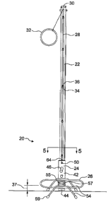
loss of aging friends and loved ones.
[0003] U.S. Patent No. 5,054,431 Coviello discloses a food supporting
platform for animal food, and a vertical guide mounted on a frame for
supporting the platform at a plurality of heights for access to the platform
by
the animal for feeding and by an operator not capable of stopping to service
the platform.
[0004] U.S. Patent No. 5,584,263 Sexton discloses a pet food dish
elevating assembly comprising: a main housing unit formed as a generally
rectangular shaped box with an essentially hollow interior, a front face and
opposing sidewalls, the interior including an electrically powered motor and
two large buttons operatively coupled to the motor, the buttons extending
through the front face, an axle being rotatably coupled within the side walls
and including at least two axle sprockets, a motor sprocket extending from
the motor and coupled to a first axle sprocket by a horizontal chain,
activation of the motor causing the motor sprocket to rotate thereby rotating
the axle of the apparatus; and at least one vertical leg coupled to the main
housing unit, a vertical chain being positioned within a leg and around a
CA 02646215 2008-12-11
-
- 2 -
second axle sprocket, a tray formed in a generally L-shaped configuration
being coupled to the vertical chain, a user depressing a first button to move
the tray upwardly, a user depressing a second button to move the tray
downwardly.
[0005] U.S. Patent No. 7,318,391 Brillon discloses a lifter for pet food
or water bowls that consists of a channel through which slides a riser lifting
a
hook onto which is hooked either a platform or a bowl or any such container.
A handle allows the user to raise the hook to any desired height at which
point it is automatically locked to that given height. By actuating a lever,
the
hook can be lowered.
[0006] There remains a need for a pet food elevating
device which is
easy for persons with reduced mobility to operate, and which may be readily
installed without providing an obtrusive structure.
Summary
[0007] A pet food elevating device comprising a food
platform, a wheel
assembly having wheels coupled to the food platform, a vertical track for
slidably receiving the wheels, an upper pulley, and a rope movably engaged
with the pulley, a first end of the rope being coupled to the food platform,
is
provided. In some embodiments, the pet food elevating device may include a
ring attached to a second end of the rope. The pet food elevating device may
include a projection on the food platform, and the projection may be
engageable with the ring to secure the pet food elevating device at a
predetermined height. The upper pulley may be coupled to an upper portion
of the vertical track.
[0008] In one exemplary embodiment, the pet food elevating
device has
a food platform with a vertical portion and a horizontal portion, and a
securing projection extending approximately horizontally from a first side of
the vertical portion. In this exemplary embodiment, the pet food elevating
device also has a food cradle, being an oval-shaped element coupled to the
CA 02646215 2008-12-11
- 3 -
horizontal portion of the food platform, the oval-shaped element being sized
to support a rim of pet food dishes. The pet food elevating device also
includes a wheel assembly coupled to a second side of the vertical portion of
the food platform, the wheel assembly comprising two pairs of wheels. The
pet food elevating device has a vertical track, and the two pairs of wheels
are
slidably engaged with the vertical track. A pulley is coupled to an upper end
of the vertical track, and a rope is movably engaged with the pulley, a first
end of the rope being coupled to the food platform, and a second end of the
rope being coupled to a ring. The ring is engageable with the securing
portion to secure the pet food elevating device is secured at a predetermined
elevation.
[0009] In addition to the exemplary aspects and embodiments described
above, further aspects and embodiments will become apparent by reference to
the drawings and by study of the following detailed descriptions.
Brief Description of Drawings
[0010] Exemplary embodiments are illustrated in referenced figures of
the drawings. It is intended that the embodiments and figures disclosed
herein are to be considered illustrative rather than restrictive.
[0011] Figure 1 is a front view of an embodiment of a pet food
elevating device in a lowered configuration.
[0012] Figure 2 is a front view of the Figure 1 embodiment of a pet
food elevating device fixed at a predetermined raised elevation.
[0013] Figure 3A is a side view of an embodiment of a food platform.
[0014] Figure 3B is a side view of a second embodiment of a food
platform.
[0015] Figure 4 is a perspective view of an embodiment of a food
platform and a food cradle.
[0016] Figure 5 is a close-up cross-sectional view of portions of the
Figure 1 embodiment taken along line 5-5. Selected components of the pet
CA 02646215 2008-12-11
- 4 -
food elevating device have been omitted to more clearly show the
construction of the Figure 1 embodiment.
[0017] Figure 6 is a perspective view of an embodiment of a food
cradle
with pet food dishes in the food cradle and a feed tray coupled to the food
cradle.
Description
[0018] With reference to Figures 1 and 2, the illustrated embodiment
of
a pet food elevating device 20 includes a vertical track 22, a food platform
24, an optional food cradle 26, a rope 28, an upper pulley 30, and a handle
32.
[0019] In use, the vertical track 22 may be affixed to a structure
such as
a wall, support beam, door, or other suitable supporting structure in an area
where it is desired to feed a pet. In the illustrated embodiment, the vertical
track 22 may include key hole hangers 34 to receive mounting screws 36 to
secure the vertical track 22 in the desired location. Other mechanisms of
securing the vertical track 22 in place, such as through the use of nails or
other suitable securing members, or glue or other adhesives, may also be
used. While the vertical track 22 is preferably installed in a vertical
orientation, it will be apparent that the vertical track 22 could be disposed
in
other orientations, for example at an angle of several degrees away from the
vertical, and still achieve the desired function of elevating pet food.
[0020] Conveniently, the vertical track 22 may be installed so that
its
base is just slightly above the ground, leaving a gap 37, to permit the area
under the pet food elevating device to be easily cleaned. If the vertical
track
22 is installed above the ground, it should be installed sufficiently close to
the
ground that wheels 38, described below, will not drop out of the vertical
track 22 when the pet food elevating device 20 is in its fully lowered
position.
[0021] The upper pulley 30 may be coupled to an upper end of the
vertical track 22, as shown in the illustrated embodiment. Alternatively, the
CA 02646215 2008-12-11
- 5 -
upper pulley 30 may be coupled to the wall at a suitable elevation using
screws, nails, adhesives, or other suitable fasteners, for example, above or
adjacent to the vertical track 22, so as to allow the pet food elevating
device
20 to be raised and lowered to the desired height. The upper pulley 30 may
be a conventional pulley, or may be made of a smooth piece of metal, wood,
plastic, or other material which allows the rope 28 to move smoothly over the
pulley 30.
[0022] With particular reference to Figure 3A, the illustrated
embodiment of the food platform 24 includes a support plate 40. Support
plate 40 includes a vertical portion 42 and a horizontal portion 44. However,
other configurations of the food platform 24 are possible, so long as the food
platform 24 supports both a wheel assembly 45 and pet food dishes 48. The
wheel assembly 45, including the wheels 38, may be coupled to the vertical
portion 42 of the support plate 40, for example by a bolt 43 as illustrated,
or
by using glue, welding, or other suitable attachment methods. The wheel
assembly 45 may be a standard wheel assembly, such as those commonly
used in the construction of closets or other sliding doors. In the embodiment
illustrated in Figure 3A, the wheel assembly 45 includes two longitudinally
aligned pairs of wheels 38 coupled to a vertical plate 47 through axles 49.
The vertical plate 47 is in turn coupled to a securing plate 51, which is
attached to the vertical portion 42 of the support plate 40, for example by
the
bolt 43.
[0023] Any suitable number and configuration of wheels 38 which
allows the food platform 24 to travel within the vertical track 22 may be used
for the wheel assembly 45. For example, the wheels 38 could be coupled
directly to the sides 53 of the vertical portion 42 and the support plate 40
sized appropriately to permit the wheels 38 to slidingly engage with the
vertical track 22. Alternatively, a single wheel 38 could be rotatably coupled
directly on each side 53 of the vertical portion 42 of the support plate 40
and
the support plate 40 sized appropriately to permit the wheels 38 to slidingly
CA 02646215 2008-12-11
- 6 -
engage with the vertical track 22 to provide the wheel assembly 45, as
illustrated in Figure 3B.
[0024] The food platform 24 may further include a securing projection
46 on the support plate 40. In operation, the handle 32 may be fitted over the
securing projection 46, thereby holding the pet food elevating device 20 at a
predetermined elevation, which may conveniently be an elevation that allows
a person to fill or change pet food dishes 48 secured in the food cradle 26
without having to bend over or crouch down towards the floor. In some
embodiments, the handle 32 may be a ring made of metal or plastic, or a
flexible material such as rope or rubber, or other suitable material. The
handle 32 may be coloured. A large colourful ring is particularly
advantageous to ensure ease of use of the pet food elevating device 20 by
elderly persons, who may have reduced cognitive capacities as well as
decreased mobility. Alternatively, other mechanisms may be used to support
the pet food elevating device 20 at a predetermined height, such as a clip at
the free end of the rope 28 or on the support plate 40. Additionally, a series
of projecting pegs could be provided on the exterior of the vertical track 22,
which would allow the pet food elevating device 20 to be secured at a
plurality of predetermined elevations.
[0025] The support plate 40 may be provided with a hole 50, through
which one end of the rope 28 may be inserted and secured. The rope 28 may
be secured to the support plate 40 by tying a knot, or by other methods than
via insertion through the hole 50, such as being secured by a suitable glue or
adhesive, or by a clamp or other holding device secured to the support plate
40.
[0026] With reference to Figure 4, the support plate 40 additionally
provides a platform for securing the optional food cradle 26. The food cradle
26 functions to support the pet food dishes 48, although it will be apparent
that the construction of the food platform 24 may be so as to achieve this
function, or alternatively that the food platform 24 could be integrally
formed
CA 02646215 2008-12-11
- 7 -
with the illustrated food cradle 26. In some embodiments, the food cradle 26
may be easily removable from the food platform 24, so that it may be
separately used to support the pet food dishes 48 apart from the pet food
elevating device 20.
[0027] In the illustrated embodiment, the food cradle 26 is an oval-
shaped element that is secured to the horizontal portion 44 of the support
plate 40 by optional cross bars 55 extending parallel to the horizontal
portion
44 of the support plate 40 across the central portion of the food cradle 26.
Preferably, the optional food cradle 26 is made from plastic coated wire or
formed from plastic, for ease of cleaning. The cross bars 55 may be secured
to the horizontal portion 44 of the support plate 40 by tape 57, or
alternatively by clamps, clips, elastics, rope or other securing elements. In
the illustrated embodiment, the food cradle 26 supports a rim 52 of the pet
food dishes 48 when the pet food dishes 48 are placed on the food cradle 26.
However, the food cradle 26 could be shaped and designed to accommodate
pet food dishes of any shape or size. For example, the two halves of the food
cradle 26 (or, alternatively, the food platform 24) could further include
baskets or additional cross bars 55 to support pet food dishes without rims.
Alternatively, the food cradle 26 or a portion of the food platform 24 could
be formed as a horizontal platform, to support a base of the pet food dishes
48.
[0028] The food cradle 26 or the food platform 24 may optionally
include legs 54, to support the pet food dishes 48 just slightly above the
ground when the pet food elevating device 20 is in a fully lowered position.
The legs 54 help to ensure that the pet food dishes 48 are not dislodged from
the food cradle 26 when the pet food device 20 is lowered. In the illustrated
embodiment, the legs 54 are formed from single pieces of wire or plastic
which may be bent to or formed in the desired shape and secured to the outer
edges of the food cradle 26 with glue or other suitable adhesives. The legs
54 may optionally include rubber stops 59 at the free ends of the legs 54, to
CA 02646215 2008-12-11
- 8 -
ensure that the legs 54 rest securely on the floor, and do not scratch any
surface finishing on the floor. The legs 54 could alternatively be secured to
the support plate 40, or other portions of the food platform 24.
[0029] With reference to Figure 5, the wheels 38 are positioned so as
to
slidably engage with (i.e. run vertically in) the vertical track 22. In the
illustrated embodiment, the vertical track 22 includes a rear surface 56, two
side surfaces 58, and two front rail portions 60 that project inwardly from
the
side surfaces 58. The wheels 38 are slidably engaged between rear surface
56 and respective front rail portions 60, thereby ensuring that the food
platform 24 is securely retained in the vertical track 22 while permitting
smooth upward and downward movement of the food platform 24. The
smooth upward and downward motion achieved by the use of the wheels 38
sliding in the vertical track 22 in response to the force applied by the rope
28
running through the pulley 30 contributes to the ease of use of the pet food
elevating device 20 for persons with impaired mobility.
[0030] In operation, the wheels 38 are inserted within the vertical
track
22, which has been secured at the desired location as described above. A
first end 64 of the rope 28 is secured to the food platform 24, and the free
end of the rope 28 is passed over the upper pulley 30. The handle 32 is then
attached to the free end of the rope 28, for example by tying a knot around
the handle 32. The pet food elevating device 20 may then be easily moved
upwardly by a user pulling on the handle 32, and downwardly by a user
releasing the handle 32. To secure the pet food elevating device 20 at a
predetermined elevation, the handle 32 may be passed over the securing
projection 46, thereby holding the pet food elevating device 20 at a
comfortable elevation for filling or changing the pet food dishes 48, or to
permit the area below the pet food elevating device 20 to be easily cleaned.
Preferably, the length of the rope 28 and the position of the handle 32 are
such as to ensure that the pet food elevating device 20 is secured at a height
so that a user of the pet food elevating device 20 does not have to bend over
CA 02646215 2008-12-11
- 9 -
or stoop to place food or water on the pet food elevating device 20, or to
change the pet food dishes 48 on the food cradle 26. For example, a suitable
length for the rope 28 may be 7 feet. The rope 28 may be made of nylon, or
may be a piece of string or other material that can slide easily through the
pulley 30, and which is strong enough to support the pet food dishes 48 when
these are full.
[0031] With reference to Figure 6, a further embodiment of a food
cradle 26, including an optional feed tray 62 coupled to the food cradle 26,
is
shown. The optional feed tray 62 may be of any desired shape or size, and
may be conveniently secured to the pet food elevating device 20 at the legs
54, using a suitable adhesive or securing member. The optional feed tray 62
may alternatively be secured to the food cradle 26 or the food platform 24,
using, for example, a suitable securing member such as a clip, clamp,
elastics, rope, or a suitable adhesive.
[0032] While a number of exemplary aspects and embodiments have
been discussed above, those of skill in the art will recognize certain
modifications may be made within the scope of the invention. For example,
= the food cradle 26 could be replaced by a level platform secured
to the horizontal portion 44 of the support plate 40 of the food
platform 24;
= the horizontal portion 44 of the support plate 40 could be
omitted, and the pet food cradle 26 securely coupled directly to
the vertical portion 42 of the support plate 40;
= one or more of the pet food dishes 48 could be integrally formed
with the food cradle 26 or the food platform 24; or
= a pair of vertical tracks 22 could be used, with one set of wheels
38 on one wheel assembly 45 movably engaged in each of the
tracks.
CA 02646215 2008-12-11
- 10 -
It is therefore intended that the following appended claims and claims
hereafter introduced are interpreted to include all such modifications as are
within their true scope.