Note: Descriptions are shown in the official language in which they were submitted.
CA 02646360 2013-11-21
Title
SELF-RETRACTING LANYARD AND
BRAKING MECHANISM WITH PAWL LOCKOUT
=
Field Of The Invention
[0002] The present invention relates to a self-retracting lanyard, or
"SRL",
intended for mostly industrial uses, but also suitable for certain
recreational uses. The
invention further relates to the larger family of controlled descent devices,
especially
those used with a harness to protect their wearers from a sudden, accelerated
fall arrest
event.
- Background Of The Invention .
[00031 Self-retracting lanyards have numerous 'industrial end uses
including but not
limited to those for: construction, manufacturing, hazardous
materials/remediation,
asbestos abatement, spray painting, sand blasting, welding, mining, numerous
oil & gas
industry applications, electric and utility, nuclear energy, paper and pulp,
sanding,
grinding, stage rigging, roofing, scaffolding, telecommunications, automotive
repair
and assembly, warehousing and railroading to name a few. Some tend to be more
end
1
CA 02646360 2008-09-08
WO 2007/106207 PCT/US2007/001020
=
use specific than others, like the building/construction system of Franke U.S.
Patent
No. 6,695,095; or the roof anchoring system of Ostrobod U.S. Patent No.
5,730,407.
[0004] There are numerous self-retracting lanyards, or lifelines, in the
field of fall
protection safety equipment. They can and should be worn by an individual when
there is any risk of falling. Such self-retracting lanyards generally consist
of a housing
that includes a rotatable drum or hub around which a lifeline, typically made
of
webbing, cable or even rope, is wound. The drum rotates in a first direction
to unwind
(or "pay out") the line from its housing when a certain level of tension is
purposefully
applied. When that degree of tension is reduced or released, the drum/hub can
slowly
rotate in a reverse direction causing the line to retract or rewind about
itself in a desired
manner. Such housings further include a braking mechanism or assembly for
stopping
drum/hub rotation when the line unwinds too rapidly, i.e., faster than its
predetermined
maximum velocity for normal pay out. Such sudden line pay outs are an
indication
that the lanyard wearer/user has experienced a fall that needs to be stopped
or arrested.
[0005] Should an unintentional, accidental fall commence, the braking
mechanism
in the housing of the SRL engages. It is meant to stop the SRL wearer from
falling too
far. After the initial fall has been arrested, the present invention prevents
subsequent
(typically incremental) line pay outs caused, in part, by the elastic nature
of the line
itself ¨ in essence, an unintentional, bungee-jumping "rebound" that can place
an
undue strain on many current lanyard braking mechanisms while possibly
jeopardizing
the safety/recovery of the SRL wearer as well.
2
CA 02646360 2013-11-21
[0006] SRL 's typically connect at one end to an anchorage point, often on
the
support structure at or near where a user is performing certain assigned
tasks. The line
from the SRL housing is clamped (or otherwise attached) to a harness worn by
the
worker. One representative harness is shown and described in Reynolds et al
U.S.
Patent No. 6,804,830.
[0007] Known models of SRL's include those disclosed in Schreiber et al
U.S.
Patent No. 6,810,99; Wolner et al U.S. Patent No. 5,186,289, Wolner U.S.
Patent No.
48'77,110 and Wolner et al U.S. Application Serial No. 10/914,631, which
published on
March 10, 2005 as US20050051659. None of these devices, however, address the
issue of line rebounding inhibition to the same degree as the present
invention.
[0008] It would be desirable, therefore, to develop a self-retracting
lanyard with a
braking mechanism having a lockout element which prevents the pawl from being
released during rebounding.
Summary Of The Invention
=
[0009] Generally, the present invention provides an improved self-
retracting
lanyard that will stop or arrest a fall event while reducing the risk of
rebounding or
drum/hub ratcheting. More particularly, the present invention provides an
improved
braking mechanism for use in a self-retracting lanyard wherein a line (web or
cable) is
wound around a rotatable drum held in a housing: Such braking mechanisms
typically
include a plurality of pawls for engaging with a toothed plate (or speirad) in
a first
3
CA 02646360 2008-09-08
WO 2007/106207 PCT/US2007/001020
plane of rotation during a fall event. The present invention improves upon
existing
SRL braking mechanisms by incorporating at least one pawl lockout element,
preferably comprising a spring-like deformable material that will flexibly
engage with
a stationary (i.e. non-rotating) component of the SRL, preferably one or more
distal
ribs in the housing interior. Preferably, the pawl lockout element is
positioned in a
plane parallel to the plane containing the pawls of the braking mechanism. A
preferred
deformable material for the pawl lockout element of the present invention is a
small 0-
ring made from synthetic rubber.
=
[0010] The present invention represents an improvement over known SRL's by
keeping its braking mechanism pawl or pawls engaged for an increased duration.
Using mechanical means to hold such pawls in place, the present invention
actually
increases the amount of backward rotation of the drum that is permitted while
keeping
the braking mechanism locked, nearly doubling the amount of rotation that
would be
possible by geometrically maximizing the interaction between the pawl and
teeth tips
of the sperrad plate.
[0011] Preferably, the present invention has more than one pawl lockout
element
for precluding drum ratcheting,- i.e., the incremental backward rotation of
the drum
after an initial fall arrest.
[0012] With the advantages and other improvements of the present invention,
a
plurality of' pawl lockout elements keep the pawls of such braking assemblies
in a
4
=
CA 02646360 2008-09-08
WO 2007/106207 PCT/US2007/001020
locked position after a fall arrest thereby rendering the SRL wearer/user more
safe and
secure from post-fall arrest release or rebounding.
Brief Description of the Drawings
[0013] Further features, objectives and advantages of the present
invention shall
become clearer with respect to the following detailed description of preferred
embodiments made with reference to the accompanying drawings in which:
[0014] Figure lA is a perspective view of a fully assembled, self-
retracting lanyard
= (SRL) having the braking mechanism with the pawl lockout element of the
present
invention;
[0015] Figure 1B is an exploded, partial cutaway of the housing from
Figure 1A
showing one preferred embodiment of distal ribs extending inwardly from the
same;
0016] Figure 2 is a perspective view of one preferred embodiment of a
drum
braking mechanism of the present invention as would be attached to a
stationary
hoUsing frame (not fully shown);
[0017] -Figures 3A through 3C are three views for schematically showing
the
braking mechanism with pawl lockout element of the present invention: (i) in
its
normal operating state (Figure 3A); (ii) in its locked state, engaged with the
sperrad
CA 02646360 2008-09-08
WO 2007/106207 PCT/US2007/001020
teeth after a fall arrest (Figure 3B), and (iii) in its lockout mode with the
lockout
element compressed against a distal rib on the housing interior (Figure 3C);
[0018] Figure 3D illustrates the increased angle of reverse rotation that
can be
sustained with the present invention while still remaining in a locked state;
and
[0019] Figures 4A through 4D are the top, bottom, side and front view of a
preferred embodiment of a pawl lockout ,element of the present invention
mounted on a
cam follower.
Description of Preferred Embodiments
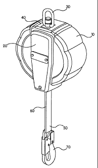
[0020] Referring now to Figure 1A, there is shown a typical, self-
retracting lanyard
fully assembled. The improved braking mechanism with the pawl lockout element
of
the .present invention is internal to that SRL unit and is not visible in that
view. But
portions of the same are better illustrated in the exploded, partial cutaway
of Figure 1B.
Such SRL's include a housing 10 about which is wrapped a cover 20, removable
for
easier servicing. Housing 10 has at its one end (directionally, at the top of
Figure 1A)
an anchor connector 30 for the SRL wearer/user to fasten the unit to an
anchorage
point. On this particular model, there is further shown a load indicator
button 40 for
quickly showing that this particular unit has not undergone a fall arrest and,
as such, is
safe to be used that day.
6 =
CA 02646360 2008-09-08
WO 2007/106207 PCT/US2007/001020
[0021] Below the housing 10 in Figure 1A, there extends a line 50, in this
case
made from nylon webbing, though it is to be understood that the braking
mechanism of
the present invention can also be used with SRL lines made from metal cables
and/or
rope, all of which can undergo their own degrees of line rebounding. SRL's
with
drums of wound webbing are preferred in certain situations because they are
usually
lighter in weight than their cable counterparts. At the lower end of line 50,
Figure lA
shows the stitching 60 that reinforces the connection of line 50 about
snaphook 70. It
is to be understood, however, that numerous other means are known for
connecting
SRL units to a wearer's given safety harness.
[00221 As can be better seen in Figure 1B, the interior side walls of
housing 10
preferably include a distal rib 80. In this embodiment of the present
invention, rib 80
serves as the fixed or stationary contact point for interacting with a
preferred pawl
lockout element as described in greater detail below. To a lesser extent,
distal rib 80
can be supplemented with, or fully replaced by, an inwardly extending
protrusion (or
post) from the housing front inner wall and/or an upwardly extending post from
the
overall SRL frame that runs through housing 10. In later figures, portions of
that
housing frame are depicted as item F where appropriate.
[00231 Within housing 10 of the SRL, there is contained a braking mechanism
100.
Though not fully shown in Figures 2 and 3A through 3D, that mechanism
preferably
consists of a plurality of pawls 110 acting beneath a cam plate 120 for a
drum/hub unit
(not shown) rotatably attached to housing frame F. Line 50 would be repeatedly
7
CA 02646360 2008-09-08
WO 2007/106207 PCT/US2007/001020
unwound from, then rewound about that drum/hub unit in the normal operation of
this
SRL. In this embodiment of the present invention, there is a cam follower 130
fixedly
attached to an end of pawl 110. In Figure 2, there is shown a pair of pawls
110 and
cam followers 130 positioned 180 degrees apart beneath a generally hexagonally-
shaped, outer cam plate 120. One embodiment of cam follower 130 is described
in
greater detail with respect to Figures 4A through 4D hereinbelow.
[00241 A
preferred pawl lockout element 220 of the present invention is shown, in
different modes of operation in the three schematic views of Figures 3A
through 3C.
On Figures 3A and 3A the typical direction of drum rotation., during web
unwinding or
pay out from the housing, is indicated by arrow A. Figure 3A depicts the
normal
operating condition of a pawl 110 interacting with teeth 140 that extend
outwardly
from a sperrad 150 that rotates around a central axis mounting, all beneath
the confines
of outer hexagonal cam plate 120. Cam
follower 130 on pawl 110 moves in
conjunction with the perimeter of hexagonal cam plate 120 in this SRL braking
mechanism. Preferably, pawl lockout element 220 comprises flexible element 200
mounted on a post 210. Flexible element 200 is preferably positioned parallel
to the
plane of rotation of sperrad 150. For the particular point of rotation
depicted in Figure
3A, there is no contact of flexible element 200 on post 210 mounted on cam
follower
130 with the distal rib 80 extending inwardly from a sidewall of housing 10.
[0025] In
its second mode of operation (as shown in Figure 3B), the braking
mechanism of the present invention has been activated and is in a first locked
position.
8
CA 02646360 2008-09-08
WO 2007/106207 PCT/US2007/001020
In such a state, tip T of pawl 110 rests in root R of sperrad 150 adjacent a
given tooth
140 of that sperrad. Through the corresponding movement of cam follower 130
mounted on pawl 110, flexible element 200 on post 210 makes contact With
distal rib
80.= During rebounding, sperrad 150 and cam plate 120 rotate in a reverse
direction
(indicated by arrow B in Figure 3C); however, flexible element 200 on post 210
flexibly compresses against distal rib 80 to keep pawl 110 in a locked
position relative
to sperrad 150. For ease of comparing the relative positions of sperrad 150
and cam
plate 120' between Figures 3B and 3C, Figure 3D was included. Figure 3D better
illustrates how the braking mechanism of the present invention is able to
increase the
maximum permitted rotation of sperrad 150 and thus of the drum to about twenty-
eight
degrees (angle M), or nearly double the thirteen degree (13 ) angle of
rotation
otherwise achievable by only manipulating relative sperrad tooth and pawl tip
geometries to remain in the locked position.
100261 Figures 4A through 4D show one preferred embodiment of the pawl
lockout
element of the present invention from a top view perspective (Figure 4A),
corresponding bottom view (Figure 4B), side view (Figure 4C) and front view
(4D). In
each view, the flexible element 200 (preferably an 0-ring) is fully or
partially visible
on the upwardly, outwardly jutting post 210 which is mounted on cam follower
130.
As .better seen in Figures 4C and 4D, post 210 preferably has a groove G for
receiving
and holding an 0-ring thereon. Preferably, the 0-ring is made of a synthetic
rubber,
more preferably EPDM (an ethylene propylene diene monomer). It is to be
understood, however, that other materials can be substituted therefore in
order to
9
CA 02646360 2008-09-08
WO 2007/106207 PCT/US2007/001020
provide a flexible element for engaging with a stationary component of the SRL
unit
extending from an interior surface of housing 10 itself and/or from one or
more points
on the permanent frame F running through the SRL.
[0027] In the construction of a preferred cam follower 130, there is a cam
following surface 132 positioned above a pawl skirt region 134, the latter
serving to
hold cam follower 130 in place for flexible element 200 to effectively lockout
the pawl
in contact with skirt region 134. And as better seen in the bottom and front
views of
Figures 4B and 4D, respectively, cam follower 130 includes a crescent-shaped,
lower
outer wall 136 that defines a pawl garage 138 that non-rotatably mounts cam
follower
130 on one end of pawl 110.
=
[0028] Preferably, each pawl 110 in accompanying Figure 2 has its own pawl
lockout element, which may or may not be interconnected. If the pawl lockout
elements are configured to mechanically lock simultaneously, or near
simultaneously,
the SRL will have an even more desirable safety redundancy built in.
[0029] Other embodiments of the present invention use a plurality of pawl
lockout
elements to keep at least one pawl in a locked position, even during rebound
when the
drum/hub rotation changes direction. While any such pawl lockout element
should be
flexible and mounted on pawl 110, still similar improvements can be realized
in a
centrifugally driven brake/clutch, or in the braking elements of other
rotational
components. And while presently preferred embodiments depict a sperrad having
teeth
CA 02646360 2008-09-08
WO 2007/106207 PCT/US2007/001020
that extend outwardly from a central axis toward the housing interior walls,
it is
understood that a similar system of pawls, plates and lockout elements can be
easily
implemented in the reverse, i.e., for a braking mechanism in which the sperrad
plate
extends about the braking mechanism circumference before terminating with
inwardly
extended or protruding teeth.
100301 Pawl lockout elements were comparatively tested using both small and
large diameter 0-rings wrapped about a post mounted on a can follower. The
smaller
rings exhibited slightly better pawl lockout performance with both ring sizes
serving to
prevent drum ratcheting while not otherwise interfering with the SRL unit's
ability to
retract webbing under normal operating conditions. Also, regardless of
relative size,
the pawl lockout elements, in combination with their respective fixed contact
points,
allow the SRL and braking mechanism of the present invention to meet or exceed
all
ANSI A10.32 and Z359 standards, and the respective standards of EN and OSHA as
well.
[00311 Having .described presently preferred embodiments, it is to be
understood
that the apparatus and methods of the present invention may be configured and
conducted as appropriate for a given application. The embodiments described
above
are to be considered in all respects only illustrative and not restrictive.
The scope of the
invention is defined by the following claims rather than by the foregoing
description.
A11' changes which come within the meaning and range of equivalency of these
claims
are to be embraced within their scope.
11