Note: Descriptions are shown in the official language in which they were submitted.
CA 02646456 2008-09-11
WO 2008/048357 PCT/US2007/005750
METHOD AND APPARATUS FOR CHARACTERIZING HEAVY OIL
COMPONENTS IN PETROLEUM RESERVOIRS
BACKGROUND OF THE INVENTION
[0001] The present disclosure relates generally to the field of petroleum
reservoir formation and fluid identification, more particularly to a method of
determining heavy oil volume, and even more particularly to a method of
distinguishing movable and non-movable portions of heavy oil components from
wireline logging.
[0002] The ability to detect and quantify very viscous or heavy oil in
petroleum reservoirs becomes more and more important as the discovery of
conventional oils becomes more and more difficult while the worldwide
consumption
of petroleum products increases. Therefore, exploration and production of
petroleum
from heavy oil fields are inevitable trends as there are more proven heavy and
very
viscous oils reserves in the world than that of conventional oils.
[0003] Nuclear magnetic resonance (NMR) is one of the logging techniques
that is useful for underground formation evaluation and fluid identification.
In
principle, the capability of identifying and quantifying fluid phases in
porous media by
NMR techniques is based on the sensitivity of NMR measured quantities, such as
signal amplitude, diffusivity, relaxation times, and some combination thereof.
NMR
signature for heavy oil is characterized by very low diffusivity and short
relaxation
time, and, in extremely heavy oil reservoirs such as tar, the relaxation time
can be so
short that the signal is substantially decayed even before an NMR logging tool
can
detect it. Because the apparent relaxation time for both heavy oil and bound
water
(such as clay-bound-water, for example) are dominated by intrinsic relaxation
mechanism (defined as the combination of bulk and surface relaxation rates),
there is
a great uncertainty in distinguishing heavy oil and bound water using
relaxation time
methods, diffusion contrast-based methods, or a combination of both methods.
[0004] The bound water in formation rock generally consists of clay-bound-
water (CBYh) and capillary bound (or irreducible) water (BVI). Often these two
types
of bound water volumes do not have a sharp boundary to separate them on a T2
1
CA 02646456 2008-09-11
WO 2008/048357 PCT/US2007/005750
(transverse relaxation time) distribution, but it is generally true that CBW
resides in
smaller T2 than BVI on a T2 spectrum. When the formation contains heavy oil,
CBW
is less likely to be discernable from the heavy oil. On the other hand, there
are other
logging techniques that may be used to estimate the volume of CBW. For
instance,
the reading of GR (gamma ray) from GR logging, expressed in API (American
Petroleum Institute), is often used as a CBW indicator.
[0005] NMR relaxation time for a single-component oil, such as hexane,
exhibits a single or nearly-single exponential decay behavior. Crude oils
contain
many constituents having different carbon numbers and different molecular
structures.
Therefore the relaxation time for crude oil exhibits a broader distribution,
and the
distribution pattern often associates with the underlying crude oil
constituents. The
feature of constituent mixture in crude oil is not often characterized by
downhole
fluid-analyzing devices or by openhole logging. A single value of viscosity or
specific
gravity is usually inadequate to fully describe a system that is intrinsically
multiple
components in constituents.
[0006] The distribution of T2 is potentially useful for characterizing the
crude
oil constituents. So far, however, NMR applications for fluid identification
usually
took a different route. Instead of utilizing the rich information provided by
an oil T2
spectrum, common practice is to reduce the distribution to a single value,
often a
geometric-mean T2. Then this single value is correlated to the oil viscosity.
However,
the correlation is a less reliable quantity for heavy oil characterization,
especially for
extra-heavy oils. Additionally, this approach has failed to utilize T2
distribution for
providing the need information of fluid component analysis.
[0007] Viscosity is often a very useful parameter to describe a conventional
crude oil because it is related to the flow properties that are essential to
oil production.
However, viscosity alone cannot fully describe a heavy oil flow property
because
heavy oil may contain more complicated molecules, such as asphaltenes, which
may
affect fluid flow in different manners, such as precipitation. Thus, the
amount of
asphaltene in crude oil affects the production and transportation of heavy oil
from
formation to wellhead to surface. If one can characterize the amount of
asphaltenes in
the logging stage, one can choose the optimal production method that minimizes
the
2
CA 02646456 2008-09-11
WO 2008/048357 PCT/US2007/005750
asphlatene deposition, thereby minimizing the formation damage and pipeline
clogging.
[0008] Another method for identifying heavy oil involves actively or passively
heating the formation and the fluids therein, then performing logging
measurements at
a temperature equilibrium state and at an artificially elevated state. Because
T2 of
heavy oil is significantly affected by temperature, while T2 of water in rock
formations
is much less affected by temperature, by determining whether there is a
significant T2
upshift as temperature increases one would be able to detect the presence of
heavy oil
in the formation that is otherwise indistinguishable by a single-temperature-
state
measurement alone.
[0009] The name heavy oil comes from the fact that the density of the oil is
high. In the refinery industry, heavy oil is defined as the fuel oil remaining
after the
lighter oils have been distilled off during the refining process. For
reservoir
engineering, heavy oil is a type of crude petroleum characterized by high
viscosity and
a high carbon-to-hydrogen ratio. It is usually difficult and costly to produce
by
conventional techniques. The exact viscosity range for heavy oils varies.
[0010] Conventional crude oil may be viewed as oil that flows naturally or
that can be pumped without being heated or diluted. Crude oil is commonly
classified
as light, medium, heavy or extra heavy, referring to its gravity as measured
on the
American Petroleum Institute (API) Scale, which is measured in degrees. U.S.
industry defines light crude oil as having an API gravity higher than 31.1 ,
medium oil
as having an API gravity between 31.1 and 22.3 , heavy oil as having an API
gravity
between 22.3 and 10 , and extra heavy oil (such as bitumen, for example) as
having
an API gravity of less than 10 . Canada has only two classifications, light
oil with an
API gravity greater than 25.7 API, and heavy oil with an API gravity less
than 25.7
API. In other locations, such as the Lloydminster area of Alberta and
Saskatchewan in
Canada, heavy oil has API gravities ranging from 9 to 18 , and from the
oilsands
deposits in the Athabasca area of Alberta, Canada, heavy oil in the form of
bitumen
has an API gravity of around 8 . From the foregoing, it will be appreciated
that the
definition of heavy oil depends on the location of the deposits, having API
gravities of
3
CA 02646456 2008-09-11
WO 2008/048357 PCT/US2007/005750
22.3 to 10 API for U.S. heavy oil, less than 10 for U.S. extra heavy oil,
18 to 9
for Alberta heavy oil, and 8 for Athabasca oilsands heavy oil, for example.
[0011 ] Accordingly, and from a practical standpoint, it would be more useful
to define heavy and extra heavy oil in less rigorous terms. For practical
purposes, it
would be useful to relate heavy and extra-heavy oil based on the ability of
the crude
oil or oil components to flow, rather than the API values, because the API
value is
defined at a standard temperature and pressure condition of 1 atm and 60
degree-C,
while the heavy oil reservoirs may be at different conditions. Thus, the
viscosity
values and the recoverability of the oil at a reservoir head may be
substantially
different from the standard condition. As such, and as herein used, the terms
heavy
oil and extra-heavy oil are referred to in relation to NMR characteristics,
with heavy
oil being defined as a viscous oil that has an intrinsic relaxation time upper-
limit of
approximately 50ms (milliseconds) at reservoir condition, and extra heavy oil
as more
viscous oil that has an intrinsic relaxation time upper-limit of approximately
10ms.
Because crude oil contains hydrocarbons having a distribution of carbon-to-
hydrogen
ratio and chemical structures, a distribution of relaxation time is observed.
The faster
relaxing components are generally related to more viscous components and are
less-
likely to be producible with conventional oil recovery methods. It should also
be
noted, however, that the recoverability is also affected by the reservoir
pressure.
Thus, and as a practical matter, it is preferable not to define a clear-cut
dividing line
between heavy and extra heavy oils.
[0012] While existing petroleum reservoir analysis methods may be suitable
for their intended purpose, there remains, however, a need in the art for an
improved
analytical method of determining heavy oil volume, and of distinguishing
movable
and non-movable portions of heavy oil components within a petroleum reservoir.
BRIEF DESCRIPTION OF THE 1NVENTION
[0013] An embodiment of the invention includes a method for obtaining a
parameter of interest relating to a region investigated by a nuclear magnetic
resonance
(NMR) tool and a non-NMR tool. Data arising from the NMR tool is acquired, and
data arising from the non-NMR tool is acquired. A solution equation is
utilized for
4
CA 02646456 2008-09-11
WO 2008/048357 PCT/US2007/005750
NMR signal intensity, the solution equation being functionally related to the
NMR
data, and a solution constraint is utilized based at least partially on the
non-NMR data.
The solution equation is solved for the signal intensity subject to the
solution
constraint, wherein the solving provides information relating to the parameter
of
interest.
[0014] Another embodiment of the invention includes a computer program
product comprising a computer readable medium having computer readable program
code on or embodied in the medium, the computer readable program code capable
of
implementing the aforementioned method.
BRIEF DESCRIPTION OF THE DRAWINGS
[0015] Referring to the exemplary drawings wherein like elements are
numbered alike in the accompanying Figures:
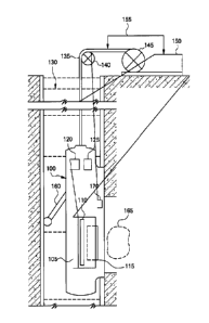
[0016] Figure 1 is an exemplary embodiment of a nuclear magnetic resonance
(NMR) well logging apparatus for use in accordance with an embodiment of the
invention;
[0017] Figure 2 illustrates a crude oil T2 distribution in accordance with an
embodiment of the invention;
[0018] Figure 3 illustrates inverted bins of a T2 distribution in accordance
with
an embodiment of the invention; and
[0019] Figure 4 illustrates a method for obtaining a parameter of interest
relating to a region investigated by a NMR tool and a non-NMR tool in
accordance
with an embodiment of the invention.
DETAILED DESCRIPTION OF THE INVENTION
[0020] In an embodiment of the invention, an analytical method determines
separately the movable and extra-viscous components of heavy crude oils, which
may
be used to assess the producible volume and the likelihood of occurrence of
asphaltene-precipitation caused formation clogging. NMR logging is used to
determine heavy oil volume, and non-NMR logging is used to provide additional
CBW information.
CA 02646456 2008-09-11
WO 2008/048357 PCT/US2007/005750
[0021 ] Figure 1 is an exemplary embodiment of a nuclear magnetic resonance
(NMR) well logging apparatus 100 suitable for detecting and quantifying a
parameter
of interest (discussed in more detail below) in a subterranean region. In an
exemplary
embodiment, apparatus 100 includes a magnetic field and field gradient
generator 105,
such as a permanent magnet for example, a RF signal generator 110, a resonance
circuit and receiver 115, a processing circuit 120, and a storage medium 125.
In an
exemplary application, logging apparatus 100 is suspended in a borehole 130
via a
cable 135, a pulley 140, a drivewheel 145, and surface equipment 150, which
controls
the lowering and raising action of cable 135 as represented by control line
155.
Apparatus 100 may be pressed against one side of borehole 130 via a control
arm 160.
Field gradient generator 105 is capable of applying a static magnetic field
gradient G
to the subterranean region, generally represented at 165. Signal generator 110
is
capable of applying a sequence of magnetic pulses to region 165, and signal
receiver
115 is capable of receiving information, and specifically nuclear magnetic
resonance
information, from the nuclei of region 165 in response to the magnetic field
gradient
from field gradient generator 105 and the magnetic pulses from signal
generator 110.
The nuclei of the region, being subjected to a pulsed NMR technique, are
productive
of NMR echo data, and characteristically have a longitudinal relaxation time
T,
distribution and an apparent transverse relaxation time T2app distribution. In
an
embodiment, the pulses from signal generator 110 and the information received
at
signal receiver 115 are controlled and processed by processing circuit 120.
Apparatus
100 may also include a non-NMR data gathering device 170, such as a gamma ray
detector, which will be discussed in more detail below. Storage medium 125,
readable by processing circuit 120, stores instructions for execution by
processing
circuit 120 for performing method embodiments of the invention, which will now
be
discussed in more detail.
[0022] A typical crude oil T2 distribution sample 200 is shown in Figure 2:
The less-viscous components are represented by the longer relaxation time
portion of
the T2 spectra, designated by reference numeral 205. The short relaxation
components
are more representative of extra viscous and macromolecular hydrocarbons
including
asphaltene, designated by reference numerals 210, 215. The extra viscous oil
and
6
CA 02646456 2008-09-11
WO 2008/048357 PCT/US2007/005750
asphaltene are the crude oil components that are less-likely to be recoverable
and may
even damage reservoir formations by clogging (asphaltene), designated by
reference
numera1215. An in-situ method that can distinguish less-viscous, flowable
(that is,
movable and recoverable), component of heavy oil (reference numera1210) from
the
extra viscous component or asphaltene (reference numera1215) is of economical
importance.
[0023] In an embodiment, the data processing method utilizes information
from a non-NMR log to improve the parameter estimates for formation
characteristics
and fluid typing from NMR data. In particular, the use of the non-NMR data can
overcome the ambiguities of NMR response to heavy oil and bound fluids.
[0024] Typical NMR data acquisition methods suitable for heavy oil well
characterization include single or plural echo trains that may be acquired
with the
same or different relaxation time parameters. In general, multiple GTE
(gradient
multiplied by interecho time) and multiple TW (wait time) are typically used
in order
to exploit the diffusion contrast and Tl/T2;,,t contrast of the saturation
fluids in porous
rocks. The intrinsic T2, defined as
1 1+ p S 1+ 1 Equa.-1
T2int T2bulk V T2bulk T2.su.1
is expected to be very close to Tl (longitudinal relaxation time) for most
typical fluids in porous media, but may be only a fraction of Tl for heavy
oils at low
reservoir temperatures and low field experiments, as is expected for fluids
under a
slow-motion (or rigid-lattice) regime.
[0025] As disclosed herein, the following terminology will be employed:
D Diffusivity of fluid.
G Magnetic field gradient. Generally, but not necessarily, G is the NMR
tool's field gradient (referred to as being intrinsic). For typical well
logging tools,
such as MREXsM tool available from Baker Hughes Incorporated, G is frequency
dependent. However, a frequency dependent G is not a requirement. In an
embodiment, the NMR logging tool has a magnetic field gradient G of about 20
or 40
Gauss/cm.
[0026] Tl Longitudinal relaxation time.
7
CA 02646456 2008-09-11
WO 2008/048357 PCT/US2007/005750
[0027] T2 Transverse relaxation time.
[0028] T2app Apparent T2, where 1IT2 opp =1/T2 ;,,, + 1ITz d,ff
[0029] T2bõik Bulk T2, which is the T2 relaxation time measured in the bulk
state. For non-wetting fluids, 1IT2bu,k "" 1/T2,;ot
[0030] T2d;ff Additional T2 decay due to diffusion in a gradient field, where
1/T2d, = (Y ' G = TE)Z D/12.
[0031] T2i,,t Intrinsic T2, 1/T2,;.t =1ITZbu,k + 11T2S,,,Jr
[0032] T2sif Surface T2, which is the surface contribution of the T2
relaxation time.
[0033] TE Interecho time, which is the time between two adjacent echoes.
In an embodiment, the NMR logging tool has an echo time spacing TE of about 1
millisecond. TE is variable to achieve the desired GTE combination in a data
acquisition scheme.
[0034] TW Wait time, which is the time between the last RF pulse applied
in the previous data acquisition event and the first excitation pulse of the
current data
acquisition event of the substantially same frequency.
y Gyromagnetic ratio
R ratio T1/T2app.
[0035] The diffusion contrast between heavy oil and water is significantly
large, often having several orders of magnitude difference. However, the
utility of
diffusion contrast for heavy oil quantification may be limited, because for
heavy oil
and bound water the sensitivity of NMR relaxation time is dominated by the
bulk
relaxation time (T2bõlk) for heavy oil, and by the surface relaxation time
(TZSõ,f) for
bound water. Both are included in the intrinsic relaxation time (T2;nt).
[0036] In order to maximize the diffusion contrast effect for detection and
quantification of different fluid types by NMR measurements, the commonly used
approach is to increase the experimentally-controlled parameters to maximize
the
contrasts of G-TE among different echo trains. The variation of G is limited
by the
hardware design configuration, and the practical upper limit of TE is
controlled by the
intrinsic relaxation time. If TE T2 for components of the fluid of interest,
the signal
8
CA 02646456 2008-09-11
WO 2008/048357 PCT/US2007/005750
intensity will be greatly decreased. Therefore, the range of GTE variation is
limited.
[0037] An embodiment of the method disclosed herein helps to reduce fluid
typing uncertainty in the short relaxation time range and to determine movable
vs.
non-movable components of the heavy oils. In a first embodiment, the heavy oil
T2
range is restricted such that the low T2 bin limit, T2min-xo, is set to one
that can be
reasonably separated from bound water or to the lower-bound of the movable oil
T2
distribution. For instance, this limit may be set as the upper limit of the
CBW, but it
may also be set to a different value, which will be described later. Once the
heavy oil
range has been reduced, any possible heavy oil components below this range is
treated
as being inclusive to CBWor bound water. For exemplary purposes, this peudo-
CBW
is referred to as CBWI. From a data processing point of view, this will not
increase
the data misfit because if a misfit did occur, it would have implied that the
diffusion
effect is significant enough to separate the two fluids, which is
contradictory to what
actually occurs. From a fluid typing interpretation point of view, this could
be a mis-
interpretation, but may be corrected as follows.
[0038] In an embodiment of the invention, a non-NMR log based CBW
(hereafter denoted CBW2), such as that derived from a gamma ray counter for
example, is computed. Alternatively, CBW2 may be obtained from other non-NMR
data, such as acoustic slowness or velocity measurements, by comparing the
porosity
difference between neutron and density logs, or any combination thereof.
[0039] In another embodiment, the non-NMR based CBW2, may be obtained
by using a prediction method, such as neural network, based on various well
log data
on similar wells or other depth intervals in the same well.
[0040] For heavy oil formations, it is expected that CBW1 >- CBW2 . The
difference
OCBW = CBW1- CBW2 Equa.- 2
is regarded as the heavy oil components that are not directly observed by the
inversion process. The difference OCBW is hereafter denoted VX_xo, to present
the
porosity volume corresponding to the most viscous components in the heavy
crude oil.
Note that VX_xO is the portion of the oil that may be heavy, contains
asphaltenes, and is
non-movable. On the other hand, if CBW1 < CBWZ is found, we interpret the NMR
9
CA 02646456 2008-09-11
WO 2008/048357 PCT/US2007/005750
based results as
CBW = CBW1 Equa.-3
and Vx-HO = 0 .
[0041 ] Even if the T2inir,_HO is chosen larger than the CBW T2,õtoff,
hereafter
denoted as T2c,CBW, the above approach is still valid. In this scenario, the
directly
inverted bins below T2c,CBw includes CBWI and partial BVI bins, as illustrated
in
Figure 3. The BVM bin in Figure 3 refers to free fluid volume. The scenario
illustrated by Figure 3 is more applicable to cases where clay bound water and
capillary bound water T2 partially overlap, or where some rock minerals that
cement
the sand are radioactive and contribute to the GR reading. In such a case, CBW
in
Equation-2 is extended to be inclusive partly of the BVI. Accordingly,
Equation-2
may still be used to treat the excess "CBW '.
[0042] By analyzing the NMR data and the non-NMR data such that each of
the data provides an apparent clay-bound-water characteristic (CBWI and CBW2),
the
difference therebetween will be representative of the volume of heavy oil in
the
region. The aforementioned analysis of CBWI versus CBW2 is referred to as
extra-
heavy oil component estimation by parameter-domain method. In another
embodiment of the invention, CBW2 is used as a constraint that builds into the
NMR
data inversion process.
[0043] In the inversion process of NMR data, the model equation may be
expressed as:
~
.(y=G=TEg
d(tk,TWPTE9)~~~m;j 1-exp TW
p 1exp[_(T1 11 ;=1 ;=, , ~2int>; c2int>
i 12
tk = (1,2,..., K) = TE
Equa.-4
which may also be expressed in a linear matrix equation format as follows:
d = Am, Equa.-5
where d is the experimental data, m is the unknown partial porosity to be
determined, and
CA 02646456 2008-09-11
WO 2008/048357 PCT/US2007/005750
TW 1 D(y=G=TE )z
A,~, = 1- exp - p exp - +' g)(tk ) Equa.-6
Rr ' T2int) ; T2int>i 12
is the matrix element.
[0044] As indicated by Equation-4, the NMR echo signal amplitude decay
may be expressed in a multi-exponential model. The general multi-exponential
model
may be divided into two categories. The first category assumes no knowledge of
fluid
properties but the broadest possible ranges of the key NMR properties, and the
intrinsic relaxation time T(Z;nt); and diffusivity Di are always known. This
is
equivalent to saying that we do not tag any molecule that contributes to NMR
signal
as a given fluid type, water, oil, or gas, but knowing that the range is set
large enough
so that the collective contribution of all molecules to the NMR echo amplitude
may be
expressed by Equation-4. The second category takes into account known
reservoir
fluid properties and forward models the NMR response for these fluids, thereby
enabling the matrix size and the number of unknowns to be reduced. For both
categories, the treatment of applying non-NMR CBW constraints is the same.
[0045] Data is acquired with different combinations of wait time TW and
interecho time TE, which may also have different echo train length K. To
obtain the
signal intensity m; j, one solves the inversion problem of Equation-4 by
solving the
matrix equation of Equation-5.
[0046] The direct inversion of Equation-6 is ill-conditioned, thus the
following regularization term is used:
Am - d 11 2+ a IW,,,m I2 = min subject to m>- 0. Equa.-7
[0047] In the above expression, the condition m - 0 is known as a positive
constraint, which simply means that all molecules cannot contribute to the
total echo
signal negatively. This is one example of applying a physical constraint.
[0048] In Equation-7, the notation "11 11" stands for the Euclidean norm of
its
vector argument (or the maximum singular value of the matrix argument). The
first
term IlAm-dil of Equation-7 comes from Equation-5, and represents the least
square
portion that serves to minimize the misfit by fitting the model matrix m to
the data
matrix d. The second term al I Wmml I of Equation-7 is a regularization term
that serves
11
CA 02646456 2008-09-11
WO 2008/048357 PCT/US2007/005750
to penalize the solution by fitting the model matrix m to the data matrix d to
a
minimum "min" level that is higher than the model and data alone, thereby
making the
solution more stable and smoother.
[0049] The regularization parameter a is estimated from the results of a
relatively inexpensive preliminary non-constrained inversion, such that it
balances the
contributions of the misfit (first) and stabilizer (second) terms. It produces
similar a
estimates to the well known L-curve or S-curve methods at a lesser cost.
Matrix W.
embodies additional information about the desired solution, which is discussed
in
more detail below. The method of regularization and Least Squares minimization
is
not limited to a particular algorithm, and employs known techniques.
[0050] To single out a useful and stable solution, the stabilizer term in
Equation-7 is defined such that W. is nonsingular. In an exemplary embodiment,
it is
either the identity matrix or an nth derivative operator, which forces the
solution to be
small, smooth, or both. However, in NMR logging applications it is often
desirable to
strive for solutions with a high spectral resolution from noisy data. Such
sharp
features may be achieved by using focusing stabilizers, where the basic idea
is
described as follows. After obtaining an initial solution, typically by a
smooth
stabilizer, very small elements ms < E max(m) are excluded. Then, a second
minimization process is run with W,õ(k, k) = max(m)/mk. A small mk results in
a large
weight in the stabilizer of the second step, forcing that particular element
to be even
smaller. The procedure is repeated until no further elements are excluded,
that is, only
those elements with significant contribution remain. In applying this process,
care
should be exercised to avoid over-focusing, where only one or a few elements
remain.
This may be accomplished by defining different termination criteria, or by
applying
additional side constraints, which will now be described.
[0051 ] Clay minerals often contain radioactive elements that may be detected
by a gamma ray (GR) detector. Clean sand or carbonate formations normally
contain
much less radioactive materials. Thus, the GR contrast is a useful indicator
for
identifying shale or clay.
[0052] The GR measured at 100% shale and 100% sand depths, along with a
porosity log, may be used to construct a clay-bound-water curve, CBWGR
12
CA 02646456 2008-09-11
WO 2008/048357 PCT/US2007/005750
GR - GRsd
CBWGR = GR GR m`'i
sh Sd arr
Or Equa.-8
GR - GRsd
CBWGR = (OTot~ of a user defined zone)
GRSb - GRsd
[0053] As is known to one skilled in the art, other CBW models may be
constructed based on GR.
[0054] While CBWGR is used herein to denote a clay-bound-water
characteristic based on non-NMR data arising from a gamma ray detector, it
will be
appreciated, as discussed previously, that other non-NMR data gathering
devices may
be employed for purposes disclosed herein. Accordingly, the term CBWGR is
intended
to encompass clay-bound-water characteristics arising from all applicable non-
NMR
data gathering devices, and not just gamma ray detectors.
[0055] For example, embodiments of the invention may use other logging
measurements, such as SP (spontaneous potential), acoustic velocity or
slowness
measurements and density & neutron measurements to construct a CBW curve
similar
to that with GR. Alternatively, a combination of the foregoing measurements
may be
used, which may improve the robustness of the non-NMR CBW estimates.
Measurement devices other than GR detectors may be useful for improving the
overall
robustness of the non-NMR CBW indicator as well as providing a robust CBW
indicator when testing regions of interest that contain minerals which tend to
reduce or
negate the effectiveness of a GR detector.
[0056] As GR is an indication of radioactive minerals that clay usually
possess, it may vary over the depths if the clay composition changes. Thus,
one must
allow tolerance on cbwGR if using it as a constraint. In an embodiment of the
invention, the following tolerances torl and tor2 are applied:
0<- CBWGR - tor, imõ CBWGR + tor2 Equa.-9
TZ;,n <cbw cutoff
D>water diffusivity cutoff
where:
CBWGR represents a clay-bound-water characteristic arising from the non-
NMR data, torl represents a first tolerance applied to CBWGR, tor2 represents
a second
13
CA 02646456 2008-09-11
WO 2008/048357 PCT/US2007/005750
tolerance applied to CBWGR, mrepresents the NMR signal intensity, T2;,,t
represents
intrinsic transverse relaxation time of investigated nuclei in the region, and
D
represents diffusivity of investigated nuclei in the region.
[0057] The two tolerances may be set by a user, or be field specific.
[0058] The CBWGR constraint is referred to as a physical constraint.
[0059] The application of the CBWGR constraint described above helps to
improve the correctness of CBW, but sometimes the heavy oil signal may still
be
spread across a wide range of diffusivity on a 2D image due to the poor
sensitivity of
diffusivity in a fast decay range. In order to make the heavy oil
identification more
easily legible from 2D NMR images, the following numerical constraint may also
be
optionally applied:
minl K(m)II2 Equa.-10
where:
K(M) = Em,j wij;
i and j represent indices that may be applied for the entire solution space or
a
subset of the solution space;
w;j represents a weighting function rule, such as, for example,
w;j = 1-exp(-d;j / max(d;j));
d;j = min(normalized distance to water line, oil line, and heavy oil line,
where
the normalized distance is the distance computed in log space of T2 and D);
T2 represents transverse relaxation time of investigated nuclei in the region;
and
D represents diffusivity of investigated nuclei in the region.
[0060] By combining Equation-5 with the two constraints of Equations-9 and
10, the following results:
14
CA 02646456 2008-09-11
WO 2008/048357 PCT/US2007/005750
Am=d
subject to
0<- CBWcR - tor, mi j CBWGR + torz
T2 ;N <cbw cutoff
fj
D>water difffusivity cutoff Equa.-11
and
min x(m) 11 z
m
[0061] Similar to solving Equation-5 with no constraints, a regularization
term
is used, such that solving Equation-11 is equivalent to solving the following
minimization equation:
Am-dII2 +alWn,m 112 + Ix(m)I2 1=min
subject to
m - 0. Equa.-12
and
0<_ CBWGR - torl mi j <- CBWGR + torz
TZ m, <ceW cutoff
D>water diffusiviry cutoff
[0062] By introducing two new variables, u and v, we convert the CBWGR
inequality constraint to the following constraints:
CBW Imi j + u= CBWcR + tor2
T2 ;. <cbw cutoff
D>water diffusivity cutoff
Imi j - v= CBWcR - tor, Equa.-13
TZ; . <cBW cutoff
D>water diffusivity cutoff
subject to
u - 0,v - 0
CA 02646456 2008-09-11
WO 2008/048357 PCT/US2007/005750
[0063] Equation-13 may be combined with Am = d of Equation-5 to obtain:
A, m, = d,
where
d
d, = CBWGR + tor,
CBWGR - torZ
m
Equa.-14
m, = u
v
A 0 0
A, = B 1 0
B 0 -1
where B is a vector correspoding to the GR constraint.
[0064] In a more compact form, Equation-12 may be reduced to the following:
I I A. m, - d, I I z+ a II K'm m II z+ 11 K(m) 112 z= min subject to m, u, v>-
0 Equa.-15
In general, each constraint of Equations-9 and 10 may be applied independent
of the other.
[0065] As can be seen from Equations-14 and 15, the solution equation, the
first solution constraint, and the second solution constraint, are combinable
such that
the solution equation may be solved using embedded solution constraints.
[0066] In view of the foregoing, and with reference now to Figure 4, a method
300 for obtaining a parameter of interest (such as the movable portion of
heavy oil
components) relating to a subterranean region investigated by a NMR tool and a
non-
NMR tool, may be applied according to the following: acquiring (305) NMR data
arising from the NMR tool, and (310) non-NMR data arising from the non-NMR
tool
(for example, the non-NMR data from a gamma ray detector is used to construct
a
clay-bound-water (CBW) characteristic); utilizing (315) a solution equation
(such as
Equation-4, 5, 7, 11, 12, 14 or 15) for solving for the NMR signal intensity
m;j, where
the solution equation is functionally related to the NMR data (d); utilizing
(320) a
solution constraint (such as Equation-9 or 10) that is based at least
partially on the
16
CA 02646456 2008-09-11
WO 2008/048357 PCT/US2007/005750
non-NMR data CBWGR; and, solving (325) the solution equation for the signal
intensity subject to the solution constraint. As a result, the solution
provides
information relating to the movable portion of heavy oil components.
[0067] In an embodiment, the solution equation includes a matrix element A
that defines NMR echo signal amplitude decay in relation to the NMR data, and
the
solving of the solution equation includes inversion of the matrix element. The
solving
of the solution equation may also include applying a regularized non-negative
least
square formulation for stabilizing and smoothing the signal intensity
solution.
[0068] In an embodiment, the solution constraint includes tolerances tor1 and
tor2 on the CBW characteristic, a numerical constraint that is functionally
related to
the signal intensity, or both.
[0069] Once the volume of heavy oil in the region has been determined, the
non-movable heavy oil portion of the volume of heavy oil in the region may be
defined to be that portion having a transverse relaxation time T2 equal to or
less than a
defined value, as illustrated in Figure 1.
[0070] An embodiment of the invention may be embodied in the form of
computer-implemented processes and apparatuses for practicing those processes.
The
present invention may also be embodied in the form of a computer program
product
330 having computer program code containing instructions embodied in tangible
media, such as floppy diskettes, CD-ROMs, hard drives, USB (universal serial
bus)
drives, RAM (random access memory), ROM (read only memory), EPROM (erasable
programmable read only memory), or any other computer readable storage medium,
wherein, when the computer program code is loaded into and executed by a
computer
335, the computer becomes an apparatus for practicing the invention. The
present
invention may also be embodied in the form of computer program code, for
example,
whether stored in a storage medium, loaded into and/or executed by a computer,
or
transmitted over some transmission medium, such as over electrical wiring or
cabling,
through fiber optics, or via electromagnetic radiation, wherein when the
computer
program code is loaded into and executed by a computer, the computer becomes
an
apparatus for practicing the invention. When implemented on a general-purpose
microprocessor, the computer program code segments configure the
microprocessor to
17
CA 02646456 2008-09-11
WO 2008/048357 PCT/US2007/005750
create specific logic circuits. A technical effect of the executable
instructions is to
distinguish movable and non-movable portions of heavy oil components from
wireline
logging.
[0071 ] While the invention has been described with reference to exemplary
embodiments, it will be understood by those skilled in the art that various
changes
may be made and equivalents may be substituted for elements thereof without
departing from the scope of the invention. In addition, many modifications may
be
made to adapt a particular situation or material to the teachings of the
invention
without departing from the essential scope thereof. Therefore, it is intended
that the
invention not be limited to the particular embodiment disclosed as the best or
only
mode contemplated for carrying out this invention, but that the invention will
include
all embodiments falling within the scope of the appended claims. Also, in the
drawings and the description, there have been disclosed exemplary embodiments
of
the invention and, although specific terms may have been employed, they are
unless
otherwise stated used in a generic and descriptive sense only and not for
purposes of
limitation, the scope of the invention therefore not being so limited.
Moreover, the
use of the terms first, second, etc. do not denote any order or importance,
but rather
the terms first, second, etc. are used to distinguish one element from
another.
Furthermore, the use of the terms a, an, etc. do not denote a limitation of
quantity, but
rather denote the presence of at least one of the referenced item.
18