Note: Descriptions are shown in the official language in which they were submitted.
CA 02646501 2008-09-22
SPECIFICATION
Toxic Gas Exposure Preventing System for
Anatomic Practice Room
Field of the Invention
The present invention relates to a toxic gas exposure
preventing ventilation system for an anatomic practice room.
Particularly, the present invention is concerned with a
system for preventing the exposure of toxic gas (e.g.,
formaldehyde gas) issuing mainly from an antiseptic such as
formalin when conducting an anatomic practice for a donor
body, i.e. specimen, having been subjected to an antiseptic
treatment using formalin for example.
Background of the Invention
An anatomic practice performed by medical students or
the like is called a medicine faculty type anatomic practice.
In this practice, plural donor bodies having been subjected
to an antispectic treatment using formalin for example are
usually dissected simultaneously on plural dissecting tables
in a practice room. Since this practice is performed in the
presence of many persons and for a long time, it is
necessary that toxic gas, e.g., formaldehyde gas, evolved
from donor bodies be removed efficiently and economically.
1
CA 02646501 2008-09-22
Generally, such toxic gas has so far been removed by
operating a ventilation fan, opening a window, or using an
air cleaner. With these means, however, a satisfactory
exposure preventing effect is not obtained. Among newly-
built anatomic practice rooms there are included those
equipped with central management type air conditioning
equipment having an intake port and an exhaust port.
However, equipment capable of removing toxic gases is
expensive in both equipment cost and maintenance cost and
thus a wide spread of such equipment is difficult. In view
of this point, various local exhaust ventilation means for
each dissecting table have been proposed (see JP 2004-
000451A, JP 2003-320220A, JP 2003-116859A, and JP 2001-
061909A). However, such local ventilation means involve
various problems such as, for example, the structure
thereof obstructing a practicing work, the application to
existing dissecting tables being difficult and the toxic
gas exposure preventing effect for students taking practice
being unsatisfactory.
Disclosure of the Invention
Objects of the Invention
It is an object of the present invention to provide a
toxic gas exposure preventing system for an anatomic
2
CA 02646501 2008-09-22
practice room which system can attain a satisfactory toxic
gas exposure preventing effect without impairing the
workability of students taking practice and which permits the
use of existing dissecting tables as they are without
requiring any special work such as installing an exhaust duct.
Summary of the Invention
The present invention firstly resides in a toxic gas
exposure preventing system for an anatomic practice room,
characterized in that a push hood having a uniform air flow
blow-off mechanism, i.e. supply uniform air flow mechanism,
and a pull hood having an air flow suction mechanism are
disposed for each of plural dissecting tables in the
anatomic practice room and independently of each of the
dissecting tables in such a manner that at least a portion
of a uniform air flow passes in contact with a donor body
on the dissecting table and is thereafter sucked into the
pull hood.
The present invention secondly resides in the above
system wherein a filter having a toxic gas adsorbing
function is installed within the pull hood.
The present invention thirdly resides in the above
system wherein the filter installed within the pull hood is
positioned lower than the air flow suction mechanism and a
3
CA 02646501 2008-09-22
cleaned air flow is exhausted into the room from a position
lower than the dissecting table.
The present invention fourthly resides in the above
system wherein a filter having a toxic gas adsorbing
function is installed also within the push hood.
The present invention fifthly resides in the above
system wherein the height of an air flow blow-off opening
surface of the push hood and/or the height of an air flow
suction opening surface of the pull hood are (is)
adjustable.
The present invention sixthly resides in the above
system wherein the height adjustment is made by a double
structure of the opening surface(s) or using a shielding
plate(s) disposed vertically movably in the opening
surface(s).
The present invention seventhly resides in the above
system wherein the height adjustment is made by a height
adjusting base portion(s) underlying the pull hood and/or
the push hood.
The present invention eighthly resides in the above
system wherein the push hood and the pull hood are disposed
opposedly to each other at both ends in a longitudinal
direction of each of the dissecting tables.
The present invention ninthly resides in the above
4
CA 02646501 2008-09-22
system wherein one push hood is disposed at a position
higher than each of the dissecting tables and a pair of
pull hoods are disposed opposedly to each other at least
outside both ends in a longitudinal direction of each of
the dissecting tables, thereby allowing a uniform air flow
to pass as a descending flow.
The present invention tenthly resides in the above
ninth system wherein a pair of pull hoods are disposed
opposedly to each other also at both ends in a transverse
direction of each of the dissecting table.
Effects of the Invention
By using the toxic gas exposure preventing system of
the present invention it is possible to effectively prevent
the exposure of toxic gas such as formaldehyde gas by using
an extremely small air flow without impairing the
workability of students taking practice. Besides, the
device of the present invention can be installed and moved
easily while using existing anatomic practice room and
dissecting tables as they are without the need of such a
work as installing an exhaust duct. Further, it is
possible to ensure a high air conditioning efficiency.
Brief Description of the Drawings
5
CA 02646501 2008-09-22
Fig. 1 is an explanatory diagram showing an example
of installation of a toxic gas exposure preventing system
according to the present invention.
Fig. 2 is an explanatory diagram showing an example
of a push hood having a height adjusting function.
Fig. 3 is an explanatory diagram showing an example
of opening surfaces of a double structure.
Fig. 4 is an explanatory diagram showing an example
of shielding plates disposed on an opening surface.
Fig. 5 is an explanatory diagram showing another
example of a toxic gas exposure preventing system according
to the present invention.
Fig. 6 is an explanatory diagram showing an example
of a pull hood used in the installation example of Fig. 5.
Preferred Embodiments of the Invention
The present invention will be described hereinunder
with reference to the drawings.
According to the present invention, a predetermined
push-pull ventilation system is installed for each of
dissecting tables in an anatomic practice room. As to in
what manner the push-pull ventilation system is to be
installed, one of the following two installation methods if
roughly classified may be adopted in the present invention.
6
CA 02646501 2008-09-22
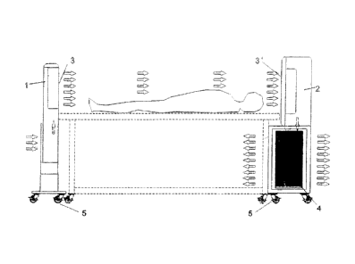
It is Fig. 1 that illustrates the whole of the first
embodiment of installation method and it is Fig. 2 that
illustrates the whole of the second embodiment of
installation method.
First, a description will be given about the first
embodiment.
The first embodiment concerns a horizontal flow or
obliquely downward flow type. As shown in Fig. 1, a push
hood 1 as an air blow-off hood is disposed on a donor body
foot-side of each dissecting table, while a pull hood 2 as
an air suction hood is disposed on a donor body head side
of the same table, or vice versa. It is preferable that
the hood height be as low as possible so as not to obstruct
a practicing work, provided the hood height is preferably
higher than the height of the donor body on the table. The
push hood may be somewhat raised upward so that an air flow
is blown off obliquely downward.
Arrows indicate air flowing directions. A uniform
air flow is blown off as a horizontal flow from the push
hood 1 toward the pull hood 2. By the uniform air flow is
meant a state in which the magnitude of the flow velocity
is substantially constant anywhere in its section when the
flow is seen in terms of a section perpendicular to the
flow. Here, a state in which variations in velocity
7
CA 02646501 2008-09-22
distribution in the absence of any obstacle is within 30%,
preferably 20%, of a mean value indicates the uniform air flow.
If the push hood 1 has an air flow blow-off opening
at a position higher than each dissecting table, there may
be used a suitable conventional push hood. However, it is
preferable to adopt such a configuration as illustrated in
the figure wherein the whole is a vertical thin plate-like
structure and the indoor air is taken in from a lower
portion on the side opposite to the air blow-off opening.
As to the pull hood, like the conventional pull hood,
it has an exhaust fan and makes the indoor ventilation
possible. It is preferable that a filter for adsorbing
toxic gas such as formaldehyde gas issued from a donor body
be installed within the pull hood used in the present
invention. The filter may be a suitable conventional
filter insofar as it can remove toxic gas typical of which
is formaldehyde gas. Also as to the push hood, there
sometimes is a case where it is preferable that a filter
for adsorbing toxic gas such as formaldehyde be installed
within the push hood, although the necessity thereof is
smaller than that for the pull hood. For preventing flue
dust or the like from getting inside and entangled with a
fan in the system or for preventing clogging of a
perforated plate such as punching metal which is for
8
CA 02646501 2008-09-22
creating a uniform flow, it is preferable that a course
dust filter be disposed in an air intake port of the push
hood. Likewise, it is preferable to dispose a course dust
filter in the pull food.
The filter-installed position within the pull hood 2
may be inside an opening surface 3' located in an upper
portion of the pull hood. However, as shown in the figure,
it is preferable that the interior of the pull hood 2 be
formed as an upper, lower, two-stage structure and that a
fan be disposed in the upper stage and a filter receptacle
portion 4 be provided in the lower stage. As the filter
there may be used a known filter capable of removing toxic
gas typified by formaldehyde gas. But, particularly, an
arranged structure of plural sheets, say, 5 to 10 sheets,
of activated charcoal filters is preferred. As shown in
the figure, the lower portion of the pull hood having the
filter receptacle portion is larger in required size than
the upper portion having an air flow sucking function, so
it is preferable that a part of the pull hood be positioned
below the dissecting table to save the space.
It is preferable that exhaust be done through the
entire surface of the lower portion of the pull hood
(arrows indicating air flowing directions, i.e., exhaust
directions into the room, are described as only right and
9
CA 02646501 2008-09-22
left directions in the figure and forward and backward
arrows are omitted).
In the conventional toxic gas exposure preventing
systems for an anatomic practice room, exhaust is generally
outdoor exhaust, but in the system of the present invention,
since very clean air resulting from filtration of toxic gas
through the filter can be exhausted in a relatively small
amount, it becomes possible to effect indoor exhaust and
hence possible to attain the reduction in size of the
system and space-saving without affecting the air
conditioning performed by an air conditioner or the like
and without the need of laying pipes or the like.
Moreover, indoor exhaust can be done in four
directions from the lower portion of the pull hood, and
even when it is necessary to install the pull hood in
contact with a wall surface, it is possible to effect
exhaust in the remaining three directions. Consequently,
in comparison with a like system permitting exhaust in only
one direction, the amount of exhaust air flowing near the
feet of apprentices can be decreased to a completely
inappreciable extent for the apprentices.
Preferably, the push hood and the pull hood are each
provided with casters 5 as shown in the figure to permit
easy movement thereof.
CA 02646501 2008-09-22
Preferably, the area of the air flow blow-off opening
surface of the push hood and that of the pull hood are
equal to each other, or the latter is the larger.
Preferably, a vertical adjusting mechanism for
adjustment to an appropriate position (height) is provided
for each of the push hood and the pull hood because all the
dissecting tables are not always equal in height or a
certain donor body may be very big. As the vertical adjusting
mechanism there may be used any of various mechanisms.
Examples of height adjusting mechanisms are shown in
Figs. 2 to 4. Fig. 3 shows an example of opening surfaces
formed as a double structure. In this double structure, if
the opening surface on the front side is made larger than
the opening surface on the inner side, the range
corresponding to the difference in size can be made an
operation range. The same figure shows a state in which
the opening surface on the front side is made vertically
movable and the height thereof has been adjusted to lower,
middle and upper stages successively from the left side.
It is preferable for the opening surface to have a
perforated body such as punching metal. According to this
method, it is not necessary to move the body itself
vertically with respect to each of the push hood and the
pull hood and therefore the height adjustment can be done
11
CA 02646501 2008-09-22
very easily. Besides, obstruction to the visual field can
be kept to a minimum because the height of the body does
not change.
On the other hand, there also is a case where the
push hood is to be installed at an obliquely upward
position for creating an obliquely downward flow. In this
case, the legs of the body of the push hood may be provided
with a vertical adjusting mechanism or a separate table
provided with a vertical adjusting mechanism may be added
to the body. Such a vertical adjusting mechanism may also
be used for the pull hood. By so doing, it becomes
possible to create a more appropriate air flow and carry
out ventilation effectively.
Fig. 2 shows an example in which the body itself is
endowed with a high adjusting function. More specifically,
the push hood is composed of a push hood body l' and a base
portion 6 easily separable from each other. Further,
plural height adjusting holes 7 are formed vertically in
both ends of a lower portion of a push hood body 1' and
height adjusting holes 7' are formed also in both ends of
the base portion 6 which is box-shaped so as to permit
fitting therein of the lower portion of the push hood body
1'. With fixing members such as bolts, the push hood body
l' is fixed at a predetermined height.
12
CA 02646501 2008-09-22
On the other hand, as to the pull hood, it is
preferable that a vertically movable shielding plate be
disposed on the air flow sucking opening surface. This
mode is shown in Fig. 4. In the example shown in Fig. 4,
two elongated shielding plates 8 are disposed at upper and
lower ends, respectively. When the opening surface is to
be positioned lower than the shielding plates, the two
shielding plates are moved to the upper end side, while
when the opening surface is to be positioned higher than
the shielding plates, the two shielding plates are moved to
the lower end side. The number of the shielding plates may
be one or three or more. In the embodiment of using a
shielding plate(s), it is preferable that the total area of
the opening surface of the pull hood be made larger by
about 10% to 30% than that of the push hood and that a part
or the whole of the opening surface be closed with the
shielding plate(s). As to the material of the shielding
plate(s), there may be used a shielding plate(s) of a
suitable material, e.g., metallic or plastic plate(s).
In the first embodiment described above, both push
hood and pull hood are disposed on both head side and foot
side outside a donor body on each dissecting table and are
not disposed in the longitudinal direction of the dissecting
table, thus causing no obstacle to students taking practice.
13
CA 02646501 2008-09-22
The second embodiment of the present invention
concerns a descending flow type. In this second embodiment,
a push hood having a uniform air flow blow-off mechanism is
disposed above each dissecting table and a total of two or
four pull hoods are disposed in two opposed longitudinal
directions or in four longitudinal and transverse directions
of the dissecting table. Fig. 5 shows a typical example
thereof. As shown in the same figure, a push hood having a
uniform air flow blow-off mechanism is disposed above the
dissecting table and a pair of pull hoods are disposed in
the transverse direction of the dissecting table in contact
with or somewhat spacedly from the dissecting table in such
a manner that openings are positioned at approximately the
same height. In case of installing the pull hoods somewhat
spacedly from the dissecting table, it is necessary that the
amount of sucked air be made somewhat large.
On the other hand, in the longitudinal direction of
the dissecting table, students taking practice perform
operations in a stand-up state in many cases and there is a
fear that the sheet which wraps the donor body may close
the opening surfaces. For this reason, it is not
preferable to dispose the push hoods so as to be in contact
with the dissecting table. In this case, as shown on the
right upper side in Fig. 5, a pair of pull hoods should be
14
CA 02646501 2008-09-22
disposed so as to leave a space enough for passing of
students taking practice. Preferably, each opening portion
is provided with a height adjusting mechanism so that the
height thereof can be adjusted in accordance with the
height of the dissecting table. As to the pull hoods
disposed in the longitudinal direction, there may be used a
divided structure to match the length of the dissecting
table.
A uniform air flow leaving the push hood is divided
in four directions near the dissecting table, but
preferably the divided flows are sucked in by four pull
hoods and toxic gas such as formaldehyde gas is exhausted.
The pull hoods in the transverse direction may be
omitted. In this case, it is preferable to lengthen the
whole of each pull hood in the longitudinal direction to a
sufficient extent or increase the air volume.
Within each pull hood there are installed a fan and a
filter for removing toxic gas such as formaldehyde as in
the first embodiment. In this case, a duct for exhaust to
the exterior is not needed at all. Besides, because of
interior exhaust, there is no air conditioning load. Also
as to the push hoods, it is preferable that the same filter
as in the first embodiment be disposed in each push hood.
Also in case of disposing pull hoods in the
CA 02646501 2008-09-22
longitudinal direction of each dissecting table in the
second embodiment of the present invention, since the pull
hoods are disposed spacedly from the working position of
the students taking practice, the pull hoods scarcely
obstruct the work. Although toxic gas-containing air also
moves toward the working position, there is little exposure
of the toxic gas to the students taking practice in the
presence of the push hoods and pull hoods properly
positioned.
By positioning as above the pull foods in the
longitudinal direction of each dissecting table and by
setting the height of the pull hoods in the transverse
direction of each dissecting table almost equal to the
height of the dissecting table, it is possible to prevent
the pull hoods from obstructing the work of the students
taking practice. Moreover, by constructing the pull hoods
movably and by separation thereof from the dissecting table,
it is possible to further improve the workability.
With the ordinary type of pull hoods alone, it is
impossible to fully suck in gas evolved at a position
spaced away from the hoods and it is very likely that the
students taking practice will be exposed to the gas.
However, by providing a uniform air flow from above, it is
possible to suppress the rise of toxic gas such as
16
CA 02646501 2008-09-22
formaldehyde gas and hence possible to greatly diminish the
possibility of exposure to toxic gas of the students taking
practice.
When smoke was allowed to rise as a substitute for
toxic gas with use of the system shown in Fig. 1 (the
opening surface area of the push hood and the pull hood =-
750 mm x 300 mm, distance between the two: 200 cm) and at a
blow-off air velocity in the push hood of 0.4 m/sec, it
turned out that all the smoke was in effect sucked by the
pull hood.
17