Note: Descriptions are shown in the official language in which they were submitted.
CA 02646579 2008-09-18
Automatic cable car facility
Technical field of the invention
The present invention relates to an automatic cable
transport installation along a closed loop line,
comprising releasable vehicles timed in stations or in
an intermediate station after passing over a released
circuit where they are driven at slow speed along drop-
off and pick-up platforms, the vehicles then being
reaccelerated and recoupled to the cable at the exit of
the station in order to constitute an endless stream of
vehicles.
Prior art
Many automatic transport means are known, that is to
say that operate without the need for the permanent
presence of supervision personnel at the drop-off and
pick-up of the passengers (or the materials).
The most common of them is the elevator having a
virtually total safety and with a minimum of operating
problems.
There also exist many people transporters and automatic
funicular railways furnished with an operation that is
back-and-forth, back-or-forth, or that has a
considerable gap between the vehicles. Exceeding a
predetermined drop-off and/or pick-up time results in a
delay specific to the only vehicle concerned.
The problem is different when such a delay affects a
vehicle forming part of an endless stream of vehicles
which, if no particular arrangement has been provided,
is forced to stop in order to wait for the delayed
vehicle. All the vehicles in the line are then stopped
to the detriment of the efficiency of the installation
CA 02646579 2008-09-18
- 2 -
and this is likely to cause a reaction of the
passengers when it involves passenger transport.
Object of the invention
The object of the present invention consists in
producing an automatic installation for the transport
of vehicles by cable, allowing vehicles released in
stations to exceed the allocated time for drop-off
and/or pick-up in stations, without affecting the
smoothness of operation of the endless stream of the
other vehicles that are in the line and in stations.
The installation is characterized in that each station
comprises an automatic maneuvering mechanism capable of
extracting the vehicles from the slow path in the
released circuit, and of transferring them to a drop-
off/pick-up position that is assigned thereto in order
of arrival, the previous vehicle having been previously
reincorporated into the slow path in place of the
extracted vehicle according to an established program.
In order to maintain the continuous operation of the
endless stream of vehicles in the line, irrespective of
the time allocated to the drop-off/pick-up of a vehicle
released in a station, any vehicle exceeding the drop-
off/pick-up time allocated thereto will not block the
path of the other released vehicles. Drop-off/pick-up
takes place at positions situated outside said path,
that is to say that the released vehicles are
systematically extracted from the normal path, during
drop-off and pick-up, and are then retrieved.
The endless stream of the vehicles in the line is not
affected, with only a "hole" in the line corresponding
to the absence of the delayed vehicle which is
immobilized at an off-path position in a station. To
return to the normal endless stream, the delayed
vehicle is reinserted one circuit afterwards in the gap
CA 02646579 2008-09-18
- 3 -
that its absence has created. It is also possible to
put the endless stream out of time over a certain
number of vehicles in order to insert the delayed
vehicle therein, and the normal timing is then resumed
by operating on the relative speeds of the vehicles
released in the other station.
Each station is also furnished with at least one
compensation position in which there is permanently an
empty reserve vehicle capable of filling an empty space
left by a vehicle delayed and stopped at the pick-
up/drop-off position. If, for any reason, a vehicle
that has to be reinserted into the path is not ready to
depart, it remains in its position thereby creating a
gap in the path, a gap that will be immediately filled
by one of the available reserve vehicles, thereby
reconstituting the timing of the installation.
The compensation position is provided only for the
drop-off of the passengers from a vehicle that would
have had to go to the pick-up/drop-off position
occupied by another delayed vehicle that has not been
able to be reinserted in its place in time.
The maneuvering mechanism for the extractions and
reinsertions of vehicles may comprise various
mechanical control members, particularly horizontal
sidings, vertical or inclined elevators, level points
bringing the vehicles to appropriate tracks.
The compensation positions are situated downstream of
the drop-off/pick-up positions relative to the
direction of the slow path of the vehicles.
The drop-off/pick-up of the passengers is carried out
when stopped, each vehicle stopping at its drop-
off/pick-up position in front of a platform, which is
furnished with a landing door placed opposite the door
of the vehicle that is stopped. The opening and closing
CA 02646579 2008-09-18
- 4 -
of the doors of the vehicles and of the landing doors
is automatic and simultaneous.
Brief description of the drawings
Other advantages and features will emerge more clearly
from the following description of particular
embodiments of the invention given as nonlimiting
examples and represented in the appended drawings,
wherein:
- figures 1 and 2 are schematic views of a
releasable cable car installation with one and two
segments;
- figure 3 shows a schematic view of an end station
of an automatic installation fitted with an operating
device with actuation sidings according to the
invention;
- figures 4.0 to 4.47 represent the successive
phases of a normal operation of the installation with
vehicles A, B, C, D entering the station, the vehicle E
being the reserve vehicle in the compensation position;
- figures 5.0 to 5.47 illustrate the sequence of an
exceptional operation of the system when the
drop-off/pick-up in a vehicle exceeds the time
allocated thereto;
- figures 10 and 11 represent schematic views in
section of an installation, wherein the maneuvering
device consists of a set of respectively vertical and
inclined elevators;
- figures 12 to 15 relate to various installations
in which the maneuvering device consists of a set of
points;
- figure 16 relates to another installation with
mixed use of sidings and points;
- figures 17 and 18 show respectively views in plan
and in elevation of the system of opening and closing
the landing doors.
CA 02646579 2008-09-18
- 5 -
Description of particular embodiments
With reference to figures 1 and 2, a plurality of
vehicles 1 move on a track 5 in a closed loop from a
first station 2 to a second station 3, if necessary
with an intermediate station 4 (figure 2). The vehicles
1 return in the reverse direction over another parallel
track 6 thanks to one or more carrier or puller
cable(s) in the case of a cable car, or any other track
and means of traction for other types of conveyors.
Between the various stations 2, 3, 4 of the loop, the
vehicles 1 move at great speed, for example at several
meters per second, and are distributed evenly, with
reduced time intervals of the order of a few seconds.
On entering one of the end stations 2, 3, the vehicles
1 are released from the cables at the releasing zone 7,
and then are decelerated over a certain length in the
deceleration zone 8. They then travel at slow speed
along a released circuit furnished with a contour 9
turning them round, and pass, depending on the type of
stations, in front of drop-off and pick-up platforms
10, 11 situated either in the contour 9, or in lateral
rectilinear portions.
At the end of their slow path in the released circuit,
the vehicles 1 are reaccelerated in the acceleration
zone 12 and recoupled to the cable in the engagement
zone 13 at the exit of the station.
In an intermediate station 4 (figure 2) traversed by
the vehicles 1, the drop-off and pick-up platforms 14
extend laterally along the tracks 5, 6, the vehicles 1
being, as in the end stations 2, 3, released, slowed
down before passing in front of the platforms, and then
accelerated and engaged afterwards.
CA 02646579 2008-09-18
- 6 -
In the case of figures 1 and 2, the drop-off and pick-
up platforms 10, 11 and 14 are situated close to the
main circuit of the released tracks, and are used by
the passengers when getting on or getting off. This is
the conventional operation of the releasable cable car
installations with a continuous path along the track.
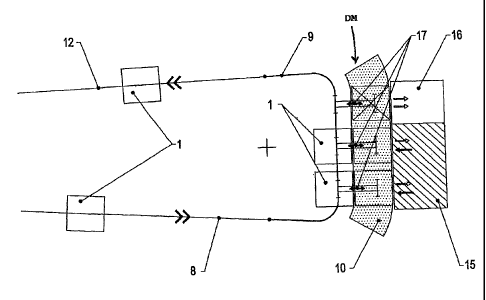
In an automatic installation of cable cars or other
releasable vehicles 1 that are timed without
supervision, the end station illustrated in figure 3 is
fitted with an automatic maneuvering mechanism DM in
order to carry out the extraction and reinsertion of
the released vehicles 1 in the contour 9. The
maneuvering device DM comprises horizontal actuation
sidings 17, making it possible to move the vehicles 1
in a direction across the direction of travel, so as to
extract them from the normal path for the drop-off and
return them to the circuit at the end of a
predetermined time after pick-up. The extracted
vehicles 1 are stored off-line in the location of the
platform 10, and their access doors are then placed in
front of two drop-off and pick-up positions 15 and a
compensation position 16. The passengers are dropped
off and picked up exclusively when the vehicles 1 are
stopped.
The compensation position 16 is only provided for
dropping off the passengers, because it has to receive
the vehicle which would have had to go to a position
occupied by another vehicle that had not been inserted
into the circuit in time. In the compensation position
16, there is therefore permanently an empty vehicle
ready to fill the gap in the event of a timing fault in
the line. The installation may have several
compensation positions 16, up to a number equal to that
of the drop-off and pick-up positions 15.
The vehicles 1 that are released and slowed down in the
deceleration zone 8 are extracted by the sidings 17
CA 02646579 2008-09-18
- 7 -
from the normal path in the contour 9 in order to reach
the drop-off and pick-up position 15 that is assigned
thereto in order of arrival. The extracted vehicle is
then stopped throughout the whole time necessary for
the passengers to get on or off, and is then reinserted
into the main path by the corresponding siding 17. The
same vehicle takes the place freed up by an extracted
vehicle according to an established program.
The compensation position 16 may advantageously be
situated downstream of the main circuit of the contour
9, and in front of the acceleration zone 12 so that the
reserve vehicle waiting in the compensation position 16
has the time to be inserted into the empty space caused
by the vehicle that has not been able to depart on
time.
Figures 4.0 to 4.47 illustrate the successive phases of
a normal operation of the installation with vehicles A,
B, C, D entering the downstream station, the vehicle E
being the reserve vehicle in the compensation position
16, which is slightly offset downstream from the drop-
off and pick-up positions 15. Each arriving vehicle A,
B, C, D goes toward the drop-off/pick-up position 15
that has just been vacated, taking the place of the
previous vehicle which is reinserted into the endless
stream of vehicles after being stopped for a certain
time at its drop-off/pick-up position 15.
Note that the reserve vehicle E remains permanently in
place in the compensation position 16 throughout all
the phases, given the regular timed operation of the
other vehicles A, B, C, D of the installation both in
the line and at stations. When they are released, the
vehicles A, B, C, D are removed from the main path in
the station, and rejoin the separate drop-off/pick-up
positions 15, the preceding vehicle having previously
been reincorporated into the slow path, in the place of
an extracted vehicle. The example of figures 4.0 to
CA 02646579 2008-09-18
- 8 -
4.47 shows two distinct drop-off/pick-up positions 15,
but it is clear that the higher the number of drop-
off/pick-up positions 15, the more time is allocated
for dropping off/picking up.
The dropping off and picking up of passengers in the
positions 15 take place when the vehicles A, B, C, D
are stopped, and are controlled by sliding doors 21,
22, one door 21 being incorporated into each vehicle,
and the other door 22 being arranged facing the
position 15. The automatic operation of these doors 21,
22 will be described in detail below with reference to
figures 17 and 18.
Figures 5.0 to 5.47 represent the sequence of an
exceptional operation of the system, when dropping
off/picking up in a vehicle exceeds the time allocated
thereto. It is the case of the vehicle B which remains
stopped in its place of the drop-off/pick-up position
15, the other place of the drop-off/pick-up position 15
also being occupied normally by the vehicle C.
The vehicle A which arrives in the station (see
figures 5.0 to 5.7) cannot go to the position 15 that
has been allocated thereto, because the preceding
vehicle B which was to vacate the position and be
reinserted into the endless stream of vehicles did not
depart. The arriving vehicle A therefore goes to the
compensation position 16 (see figures 5.8 to 5.22),
which the empty waiting reserve vehicle E which was
parked there has just vacated, in order to fill the
empty space in the endless stream of vehicles left by
the stopped vehicle B. The vehicle A is therefore
provisionally moved into the compensation position 16
(see figures 5.23 to 5.47) where the passengers can get
off. The empty vehicle A is then the reserve vehicle
and the vehicle E reinserted into the line becomes one
of the vehicles of the endless stream.
CA 02646579 2008-09-18
- 9 -
The vehicle B remains out of service at the position 15
until the phase of figure 5.16, the respective doors
21, 22 remaining open. The program established by the
programmable controller allocates a new predetermined
pick-up time to the vehicle B, and this time expires in
the phase of figure 5.38. The doors 21, 22 of the
vehicle B still remain open at this moment, and the
programmable controller places it out of service for a
new period (see figures 5.39 to 5.47). Everything
happens normally at the other adjacent position 15
where the vehicles C and D are taken out and reinserted
according to the program established for maintaining
the regularity of operation of the endless stream. The
vehicle A also remains in reserve in the compensation
position 16.
Figures 6 to 8 represent as examples the variants of
figure 3, with drop-off/pick-up positions 15 and
compensation position 16 with sidings 17 in end
stations.
In figure 6, the drop-off/pick-up positions 15 and
compensation position 16 extend in the rectilinear
portions opposite to the released circuit, respectively
upstream and downstream of the contour 9. The drop-
off/pick-up position 15 is provided for three vehicles
1 of the endless stream, while the compensation
position 16 on the branch opposite may receive two
vehicles 1. The operation is identical to that of
figure 3.
In figure 7, one of the drop-off/pick-up positions 15
of figure 6 replaces on the opposite side one of the
places of the compensation position 16.
Figure 8 illustrates the drop-off/pick-up positions 15
and compensation position 16 distributed side by side
along the contour 9, the compensation position 16 still
CA 02646579 2008-09-18
- 10 -
being placed downstream relative to the direction of
travel of the vehicles 1.
Figure 9 represents the same distribution of the drop-
off/pick-up positions 15 and compensation position 16
with sidings as figure 8, but for an intermediate
station.
Figures 10 and 11 show schematic views in vertical
section of a station in which the drop-off/pick-up
positions 15 and compensation position 16 are at a
different level relative to the platforms 10. The
extraction and reinsertion of the released vehicles 1
is then carried out by vertical elevators 19
(figure 10) or inclined elevators 20 (figure 11).
Figures 12 to 15 represent various positions of end and
intermediate stations, wherein the extraction and
reinsertion of the released vehicles 1 are carried out
thanks to level points 18. The compensation position(s)
16 is/are still placed downstream of the functional
drop-off/pick-up positions 15, and there are still
possibilities for platforms 10, 11, 14 allowing the
return to a conventional operation of the cable car.
In figure 12, two drop-off/pick-up positions 15 are
situated on two auxiliary tracks connected in parallel
on the contour 9 by points 18. The compensation
position 16 is situated in the released circuit just
before the acceleration zone 12.
Figure 13 shows three auxiliary tracks connected in
parallel on the contour 9 by points 18. Two tracks are
provided for two drop-off/pick-up positions 15, and the
third is allocated to the compensation position 16
situated downstream.
Figure 14 illustrates a position with points 18 with
two opposite platforms 11 in an end station. The drop-
CA 02646579 2008-09-18
- 11 -
off/pick-up position 15 on one of the platforms 11 is
designed for two vehicles 1, and the compensation
position 16 of the other platform 11 is designed for a
reserve vehicle.
Figure 15 is an arrangement comparable to that of
figure 9 of an intermediate station, but making use of
points 18 to divert and reinsert the vehicles 1 into
the endless stream.
Figure 16 is an arrangement comparable to figure 14,
but in which the extraction and reinsertion of the
released vehicles 1 for certain positions is carried
out with the aid of a type of maneuvering device
(siding, elevator, points), and for other positions
with different types. The normal drop-off/pick-up
positions 15 comprise sidings 17 on one side, and a
compensation position 16 on the other side of the
contour is fitted with points 18 with an auxiliary
track.
Figures 17 and 18 represent the system for automatic
access to the vehicles 1 at the drop-off/pick-up
positions 15. Each vehicle 1 is provided with a double
door 21, and the drop-off/pick-up location of each
position 15 comprises a landing door 22 that is also
double. Lyre-shaped forks 24 are attached to the
landing doors 22, and operate vertical pins 23 attached
on the top of the doors 21 of the vehicles 1 in order
to open and close them at given moments controlled by
the programmable controller.
Irrespective of the adopted arrangement using sidings
17, elevators 19, 20 or points 18, provision may be
made for the possibility of the existence of platforms
10, 11, 14 running alongside the main circuit of the
released vehicles, in order to allow a conventional
operation when the extraction systems are not used.
CA 02646579 2008-09-18
- 12 -
If the extraction system for the vehicles at the drop-
off/pick-up positions 15 is horizontal (sidings,
points), it involves platforms that can be moved
vertically and raised after the disappearance of any
vehicle from the drop-off/pick-up positions 15.
If the extraction system for the vehicles at the drop-
off/pick-up positions 15 is vertical (elevators), these
platforms may be designed to be unmovable.