Note: Descriptions are shown in the official language in which they were submitted.
CA 02646782 2008-12-15
MEASUREMENT TOOL AND METHOD OF USE
FIELD OF THE INVENTION
This invention relates to a measurement tool, and in particular to a
measurement
tool for use in determining a parameter of a stationary or moving fluid. The
measurement tool has been designed for use in borehole formation testing and
the following description will therefore relate primarily to such
applications, but the
invention is not thereby limited.
BACKGROUND OF THE INVENTION
Measurement tools are in widespread use in borehole formation testing, for
example in boreholes drilled into the earth in order to test for or recover
underground reserves of oil and/or gas. Some such tools are carried by the
drill
string and the measurements are carried out during the borehole drilling
operation
(so-called "measurement-while-drillind' (MWD) or 'yogging-while-drillind'
(LWD)
applications). Other measurement tools are used after the borehole has been
2o drilled, the measurement tools being lowered into the borehole by a cable
or wire.
In highly deviated wells conveyance may be assisted by semi-rigid tubing or by
drill-pipe. Still other measurement tools are deployed downhole for lengthy
periods of time with or without a connecting cable and are referred to as
permanent or retrievable gauges. These are usually for use in production after
the exploration phase is complete.
Tools deployed using cable having one or more electrical conductors are
generally referred to as "electric wireline toolg'. The present invention is
most likely
to be a part of an electric wireline tool, though its use in MWD/LWD or other
3o downhole applications is not thereby excluded.
CA 02646782 2008-12-15
2
One known electric wireline tool is a formation testing tool or"pump-ouY tool,
which
is used to extract a volume of fluid from a formation surrounding a borehole,
the
fluid being tested in order to evaluate the likely productivity of the oil or
gas well.
It is a recognised problem of operating formation testing tools that during
the
borehole drilling operation the fluid within the formation can be contaminated
with
drilling fluid (or "mud) filtrate typically comprising liquid and other
materials. In
order to obtain valuable test results it is of prime importance that the
formation
fluid used for analysis represents virgin formation fluid with little or no
io contamination from fluids used in the borehole drilling operation.
Drilling fluid is generally divided into oil base mud (OBM) and water base mud
(WBM). The drilling fluid pressure is maintained higher than that of the
formation,
and as a result the drilling fluid seeps into the formation, the seeping fluid
being
known as filtrate. Fine particles that cannot penetrate the formation are left
behind on the borehole wall and build up to form a filter (or "mud) cake. This
is
relatively impermeable and forms a skin substantially preventing further
ingress of
fluid. The filtrate displaces virgin formation fluid from the vicinity of the
borehole
wall, until a stable `invaded zone' results. Depending on the virgin fluid,
the type of
mud and the formation composition and structure, different degrees and depth
of
invasion occur into the formation.
The formation fluid may naturally contain a large percentage of water, of some
salinity. Water base mud is predominantiy water but need not have the same
salinity. Although perfect oil base mud has very little water, in practice it
may
contain as much as 40% water. Filtrate may include formation water from other
depths in the borehole that has mixed into the mud.
3o DESCRIPTION OF THE PRIOR ART
Traditionally, operators wishing to extract a volume of fluid from a formation
surrounding a borehole in order to evaluate the likely productivity of the
borehole
CA 02646782 2008-12-15
3
utilised drill stem testing, in which the formation fluid was pumped to the
surface
for testing. This practice has become less desirable primarily because of the
harmful environmental impact of needing to flare-off excess fluid. Also, there
is
difficulty in bringing the fluid to the surface from particular boreholes,
especially
sub-sea boreholes. Furthermore, the pressure and temperature of the fluid
changes during its movement to the surface, and these pressure and temperature
changes can cause changes in the consistency of the fluid (i.e. the fluid may
separate out or otherwise change its material characteristics) which may
invalidate the subsequent test.
To overcome the problems associated with pumping the formation fluid directly
to
the surface, formation testing tools have been developed which can undertake
at
least some of the tests downhole. One such formation testing tool is described
in
US patent 5,602,334, the tool including measurement tools able to measure
selected parameters of the formation fluid downhole. This formation testing
tool
also includes containers which can be filled with formation fluid for
transportation
to the surface for additional testing if desired.
It is of course necessary that formation testing tools such as that of US
patent
2o 5,602,334 be able to determine whether the fluid being pumped out of the
formation is virgin formation fluid, or is contaminated formation fluid, so
that the
tests are conducted only upon virgin formation fluid, and only virgin
formation fluid
is collected in the containers. For present purposes `Yirgiri' means having as
little
contamination as possible, and certainly below some threshold of
acceptability.
Many different parameters are desired to be tested downhole, some of which
assist in determining whether the fluid is virgin or contaminated, and others
which
assist the operator in assessing the likely productivity of the formation.
3o A parameter which can be measured downhole is the electrical resistivity of
the
fluid. This parameter is often used to determine whether the fluid is virgin
or
contaminated because the electrical resistivity of oil is significantly
different to that
of water-base muds. US patent application 2007/0018659 (issued as US Patent
CA 02646782 2008-12-15
4
Serial No. 7,183,778 on February 27, 2007) discloses a measurement tool for
use
in a formation testing tool, the tool measuring the resistivity of the
formation fluid.
In US patent application 2007/0018659 the resistivity of the formation fluid
is
tested as the fluid is flowing along a pipe, and this is a particularly
desirable
feature of measurement tools used in formation testing tools where the pipe
can
lie within the formation testing tool. The pipe should preferably be
substantially
linear and free from constrictions, bends or voids which would induce pressure
changes into the fluid, which pressure changes may affect the consistency of
the
lo fluid and thereby lead to a different test result than would be obtained
upon fluid
within the formation.
Another parameter which can be measured downhole is pressure, typically as
part
of a draw-down and build-up pressure test which can be used to determine the
mobility (permeability divided by viscosity) of the fluid in a formation and
therefore
help to assess the likely productivity of the formation.
Yet another parameter is the chemical constituents of the fluid, which can be
used
to determine whether the formation fluid at one depth of the borehole is the
same
2o as that at another depth, any chemical dis-similarity between the formation
fluids
at different depths indicating that the formation is not contiguous and is
instead
made up of discrete reservoirs which will make the oil and/or gas more
difficult
and expensive to recover. Chemical dissimilarity can also be used to
differentiate
virgin fluid and filtrate.
The likely productivity of an oil and/or gas reservoir is a very valuable
assessment
for operators to make as this determines the likely value of the reservoir to
the
operator. It is an object of this invention to provide a measurement tool
which can
be used in a formation testing tool and which is able to test more relevant
parameters of the formation fluid and/or which is able to test the relevant
parameters more accurately and reliably, so that the operator can make a more
accurate assessment of the productivity of a particular reservoir.
CA 02646782 2008-12-15
It is another object of the present invention to assist in distinguishing
virgin
formation fluid from invasion filtrate (contaminatiori'), recognising that
both the
water and oil components in the invaded zone are often a mixture of residual
virgin fluid and filtrate, and that virgin fluid beyond the invaded zone may
have
5 water or oil similar to that of the mud filtrate.
The measurements of density and viscosity are useful in assessing the
contamination of virgin formation fluid by mud filtrate.
io Also, the measurement of viscosity is particularly valuable in assessing
the
productivity of an oil and gas reservoir. As above indicated, a draw-down and
build-up pressure test can be used to determine the mobility k of a formation
given
by
k
77
where p is the permeability and ri is the dynamic viscosity. Thus if the
viscosity of
the fluid can be determined this will help to determine the permeability of
the
formation to the fluid within the reservoir, which is more directly related to
the
likely productivity of the formation.
2o The dynamic viscosity is related to the kinematic viscosity v and density p
by the
formula
rl=pv.
The measurement of viscosity in the present invention is a function of
kinematic
viscosity and density so that the density must be measured by some means in
order to allow a determination of the dynamic viscosity.
CA 02646782 2008-12-15
6
SUMMARY OF THE INVENTION
According to a first aspect of the present invention the measurement tool is
adapted to measure the density of a fluid. According to a second aspect of the
invention the measurement tool is adapted to measure viscosity of a fluid.
According to a third aspect of the invention the measurement tool is adapted
to
measure both the density and viscosity of a fluid.
According to its first aspect, the present invention provides a measurement
tool
io for measuring the density of fluid within a pipe, the pipe being resilient
and having
a substantially uniform. cross-section along its length, the pipe carrying an
exciter,
the exciter being connected to a signal generator, the exciter and signal
generator
being adapted to impart transverse oscillations to the pipe.
It will be understood that a resilient pipe has a resonant frequency of
transverse
oscillation, the resonant frequency being dependent upon the mass of the pipe.
When the pipe is filled with fluid the mass of the fluid affects the resonant
frequency and so the resonant frequency can be used to determine the combined
mass of the pipe and fluid contained therewithin. Since the mass of the pipe
is
2o known, and the volume of the pipe is known, the density of the fluid within
the pipe
can thereby be determined.
According to its second aspect, the present invention provides a measurement
tool for measuring the viscosity of fluid within a pipe, the pipe being
resilient and
having a substantially uniform cross-section along its length, the pipe
carrying an
exciter, the exciter being connected to a signal generator, the exciter and
signal
generator being adapted to impart rotational oscillations to the pipe.
It will be understood that a resilient pipe has a resonant frequency of
rotational (or
torsional) oscillation, the resonant frequency being dependent upon the
torsional
resilience of the pipe. When the pipe is filled with fluid the viscosity of
the fluid
affects the resonant frequency (since a particularly viscous fluid will cause
the
pipe to behave as if it is substantially solid whereas air or other fluid with
very low
CA 02646782 2008-12-15
7
viscosity will have little effect upon the pipe's resonant frequency of
rotational
oscillation).
In addition, the pipe will not oscillate only at the resonant frequency, but
will also
oscillate strongly at frequencies close to the resonant frequency when
excited.
The amplitude of the response to a forced excitation as a function of
excitation
frequency near a resonance is a peaked curve. The shape of this curve, centred
on the resonant frequency, is commonly termed a"spectrurri'. The actual shape
in
practice for resonant pipes is a'Lorentziari' curve. Depending on the
particular
io measurements or calculations made, a spectrum may be presented for example
as the ratio of oscillation velocity in response to excitation level
(impedance) or
their product (power taken from the exciter) at a constant amplitude or
constant
level of response. In the present invention the spectrum may be derived from
any
such commonly known means.
Changes in the viscosity of the fluid will not only change the pipe's resonant
frequency but will also change the spectrum as viscous friction due to
torsional
shear affects the power absorbed by the fluid at different frequencies. It is
therefore possible to determine viscosity either by observing changes in the
2o resonant frequency, or by observing changes in the shape (primarily the
width) of
the spectrum, and it is understood that changes in the width of the spectrum
are a
more accurate method of assessing changes in viscosity, especially at higher
viscosities where the spectrum is particularly broad and identification of the
peak
is difficult.
According to its third aspect, the present invention provides a measurement
tool
for measuring the density and viscosity of fluid within a pipe, the pipe being
resilient and having a substantially uniform cross-section along its length,
the pipe
carrying an exciter, the exciter being connected to a signal generator, the
exciter
3o and signal generator being adapted to impart transverse and rotational
oscillations
to the pipe.
CA 02646782 2008-12-15
8
Preferably, the pipe is 'tuned' so that when it is filled with a chosen fluid
its
resonant frequency of transverse oscillation is substantially different to its
resonant frequency of rotational oscillation. The two resonant frequencies can
therefore readily be discerned and separated for the measurement of both the
density and viscosity of the fluid. Preferably, the pipe is tuned by securing
a
chosen mass to the outside of the pipe. Desirably, the chosen mass is secured
adjacent to the longitudinal centre of the pipe.
Desirably, the same signal generator and exciter are used for both the density
and
io viscosity measurements, the signal generator and exciter being adapted to
impart
transverse oscillations at a first frequency and rotary oscillations at a
second
frequency, the second frequency being different to the first frequency.
The exciter can be separate from the detector. For example one embodiment
could use a piezoelectric transducer to excite motion and an eddy current
proximity sensor pickup coil to measure it.
The signal generator can transmit a range of frequencies to the pipe, the
signal
generator scanning across the chosen range of frequencies in a chosen period
of
time. In such embodiments the tool preferably includes a detector which is
adapted to determine the response spectrum of the oscillating pipe. The
spectrum will allow a determination of the resonant frequency and other
desired
features.
Alternatively, the signal generator can energise the pipe to oscillate close
to or at
its resonant frequency, and then the excitation can be stopped and the
decaying
oscillations observed. The pipe will oscillate at its resonant frequency
during this
decay, and it is recognised that the decay is exponential with a
characteristic
decay curve time constant which is inversely related to the spectrum line
width
that could otherwise be measured. Accordingly, measuring the decay curve can
provide information about the spectrum for use in the viscosity (and perhaps
also
density) measurements.
CA 02646782 2008-12-15
9
Alternatively again, the signal generator can be an oscillator whose tuning
element is the pipe, in similar known manner as a crystal oscillator has as
its
resonant element a mechanical resonator (crystal) that forms the tuning
element
of an electronic circuit. The signal generator thereby excites the pipe at
only a
single (resonant) frequency. As the resonant frequency changes with changes in
the density (and perhaps also the viscosity) of the fluid, the changes can be
detected by detecting changes in the output frequency of the signal generator.
In one embodiment the exciter comprises a support secured to the longitudinal
io centre of the pipe, the support carrying a pair of permanent magnets, and
the tool
has at least one electrical coil arranged adjacent to each of the permanent
magnets, the signal generator being connected to the electrical coils and
being
adapted to deliver an alternating current to the electrical coils so as to
induce a
force into the magnets and therefore into the support and pipe. Preferably,
the
permanent magnets and respective electrical coils are arranged on opposed
sides
of the pipe. Imparting a similar alternating electrical current into the
electrical coils
for both magnets causes an alternating force of similar magnitude and
direction to
be imparted to both of the magnets together, so that the pipe is caused to
oscillate
transversely. On the other hand, imparting opposing alternating electrical
currents
into the electrical coils of each magnet causes alternating forces of similar
magnitude but opposing direction to be imparted to the magnets so that the
pipe
is caused to oscillate rotationally.
In other embodiments the two magnets are replaced by a single magnet so that
it
is not necessary to calibrate the signal generator to accommodate permanent
magnets having differing magnetic fields.
The invention also provides a method of use of a measurement tool, the
measurement tool having a resilient pipe with a substantially uniform cross-
section along its length, the pipe carrying an exciter, the exciter being
connected
to a signal generator, the method comprising the steps of: {i} issuing an
alternating electrical signal from the signal generator to the exciter so as
to impart
oscillations into the pipe at a first frequency; {ii} measuring the voltage
and current
CA 02646782 2008-12-15
flowing to the exciter at the first frequency; {iii} altering the electrical
signal from
the signal generator so as to impart oscillations into the pipe at a second
frequency; {iv} measuring the voltage and current flowing to the exciter at
the
second frequency; {v} repeating steps {iii} and {iv} at third, fourth etc.
frequencies,
5{vi} determining a response spectrum across the range of frequencies used,
and
{vii} using the spectrum to determine a characteristic of the oscillations of
the pipe.
The characteristic of the oscillations of the pipe may be its resonant
frequency,
the characteristic corresponding to a chosen parameter of a fluid flowing
within
1o the pipe.
The alternation of the electrical signal may be in a number of discrete steps,
so
that the spectrum comprises a number of measured values at discrete
frequencies within the chosen range of frequencies, or it may be continuous
(or
substantially so).
Alternatively there is provided a method of determining a parameter of a fluid
within a pipe, the parameter being one of:
{i} the density of the fluid
{ii} the viscosity of the fluid
{iii} the density and viscosity of the fluid,
the method comprising the steps of:
{a} providing a measurement tool having a resilient pipe with a substantially
uniform cross-section along its length, the pipe carrying an exciter, the
exciter being connected to a signal generator,
{b} issuing an alternating electrical signal from the signal generator to the
exciter so as to impart oscillations into the pipe substantially at its
resonant
frequency,
{c} stopping the electrical signal to the exciter;
{d} measuring a characteristic of the oscillations after the electrical signal
has
stopped, and
{e} using the measured characteristic of the oscillations to determine the
parameter.
CA 02646782 2008-12-15
11
Accordingly, rather than using a "spectruni' method it is possible to use
a"decay'
method in which oscillations are imparted to the pipe substantially at its
resonant
frequency (i.e. close enough to the resonant frequency that the pipe will
adopt its
resonant frequency once the excitation has stopped) and the oscillations are
measured after the excitation has stopped.
Preferably, when the parameter is density the measured characteristic is the
resonant frequency of transverse oscillations, and when the parameter is
viscosity
lo the measured characteristic is the decay curve (and in particular its time
constant)
of rotational oscillations.
The measurement tool according to all of its aspects has additional benefits
in
multi-flow formation testing tools such as that described in US published
patent
application 2008/0173083 filed on 24 January 2007. In this formation testing
tool
two (or more) fluid flows from the formation are kept separate and are tested
separately, and a measurement tool of the present invention could be arranged
in
each flow line and direct comparisons between the two fluids could be made as
desired. Where one flow line recovers fluid from the formation surrounding the
path of the fluid recovered through the other flow line, the comparison can
assist
in determining when virgin fluid is being recovered and the volume of
formation
from which recovery is taking place.
BRIEF DESCRIPTION OF THE PREFERRED EMBODIMENTS
The invention will now be described in more detail, by way of example, with
reference to the accompanying drawings, in which:
3o Fig.1 shows a perspective view of one embodiment of measurement tool
according to the invention;
CA 02646782 2008-12-15
12
Fig.2 shows a side view of part of another embodiment of measurement tool
according to the invention;
Fig.3 shows an end view of the yoke and pipe of the measurement tool of Fig.2;
Fig.4 shows an electrical circuit suitable for exciting oscillations in the
pipe;
Fig.5 shows a representation of two spectra for the oscillations in a pipe of
a tool
such as that of Fig.1 or Fig.2;
Fig.6 shows two curves representing measurements upon the spectra of Fig.5;
Fig.7 shows two curves representing the effect of adding a mass upon the
resonant frequencies of the oscillation of a pipe;
Fig.8 shows a magnet and coil arrangement for an alternative exciter;
Fig.9 shows an exciter using two of the magnet and coil arrangements of Fig.8;
Fig.10 shows a solenoid arrangement for another alternative exciter;
Fig.11 shows an exciter using four of the solenoid arrangements of Fig.10; and
Fig.12 represents the electrical current, voltage and induced emf of an
exciter
circuit.
DETAILED DESCRIPTION
In the drawings, similar numbers are used to represent similar components in
the
various embodiments.
CA 02646782 2008-12-15
13
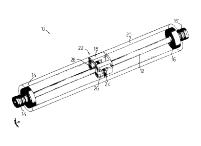
The measurement tool 10 shown in Fig.1 comprises a pipe 12, the pipe being
resilient and having a uniform cross-section along its length. In this
embodiment
the pipe has a circular cross-section. The pipe has end connectors 14,16 by
which the pipe may be sealingly connected to adjacent pipes, or else to other
components within a fluid flow line.
The end connectors are interconnected by a surrounding tube 20 which is
substantially rigid, the tube 20 acting to secure the end connectors 14 and 16
in
their relative positions, and so secure the respective ends of the pipe 12. In
one
io embodiment the pipe 12 and end connectors 14, 16 are machined from solid
and
the tube 20 is welded to the end connectors. This results in a minimum number
of
mechanical joints and therefore reduces the likelihood of a mechanical failure
in
use. Also, and importantly for the present invention it ensures torsional
stress is
transmitted from pipe 12 to tube 20 without intermediate elastic compliance or
damping due to jointing means. Such compliance or damping would not be easily
distinguished in the measurement from that due to the fluid.
By fixing the ends of the pipe 12, the pipe is able to oscillate both
transversely (or
laterally), and also to oscillate rotationally (or torsionally). The pipe can
undergo
oscillations according to its fundamental, or first harmonic, frequency (in
which the
longitudinai centre of the pipe has the maximum amplitude), or according to
its
second harmonic frequency (in which the longitudinal centre of the pipe
remains
stationary and the points approximately half way between the longitudinal
centre
and each of the end connectors undergo the maximum amplitude, or according to
its third harmonic frequency, and so on.
End connectors 14 and 16 have respective parts 14 and 15 for sealingly
connecting the pipe 12 to the external continuations of the fluid path, so
that the
volume within pipe 12 is sealed. The fluid within tube 20 is thereby separated
from the fluid under measurement and can therefore be controlled, and is
desirably air or other gas, in which case the fluid around the pipe 12 has
minimal,
effect upon the transverse and rotational oscillations of the pipe 12.
CA 02646782 2008-12-15
14
As the measurement tool 10 is to measure the density of fluid within the pipe
it is
desirable that the mass of the pipe itself be minimised, so that the tool is
more
sensitive to the mass of the fluid. As the measurement tool 10 is also to
measure
the viscosity of fluid within the pipe it is desirable that the pipe be very
susceptible
to torsional movement, so that the tool readily undergoes torsional
oscillations and
can be sensitive to the viscosity of the fluid. A titanium pipe having a
circular
cross-section with an inside diameter of around 6.4 mm (1/4 inch) and an outer
diameter of around 10 mm (3/8 inch) has been found to be sufficiently
lightweight
and torsionally resilient for the tool to be sensitive to the mass and
viscosity of the
io fluid within the pipe. In addition, when used in formation testing tools
such a pipe
is able to withstand the high pressures involved at the typical depths (around
5 -
km) with air or other gas at atmospheric pressure in the volume around the
pipe 12.
The pipe 12 carries an exciter 22 which is connected to a signal generator 32
(see
Fig.4), the exciter 22 and signal generator 32 being adapted to impart
transverse
and rotational oscillations to the pipe 12, as described below.
Similar to the connection between the pipe 12 and tube 20 described above, the
construction of the exciter 22 must be such that there is substantially no
internal
movement or elasticity of its parts, other than the required motion induced
across
the gap between the stator part fixed to tube 20 and the rotor part fixed to
pipe 12.
Any unwanted movements or elasticity would result in damping which would not
easily be distinguishable in the measurement from that due to the fluid.
In this embodiment the exciter comprises a support 24, electrical coil 26 and
electrical coil 28. The support 24 is connected to the longitudinal centre of
the
pipe 12 (i.e. connected upon the pipe 12 mid-way between the end connectors 14
and 16). As shown in the embodiment of Fig.3, the support 24 carries two
permanent magnets 30, which are preferably substantially identical (i.e. the
magnets have as near-identical magnetic fields as possible). The magnets 30
are
magnetised (or polarised) perpendicular to the plane of the paper as drawn in
Fig.3, in the same direction, as shown by the solid arrow-heads in Fig.2. The
CA 02646782 2008-12-15
electrical coil 26 lies adjacent to one of the magnets 30, and the other
electrical
coil 28 lies adjacent to the other of the magnets 30.
The flow of electricity around the coils 26 and 28 induces an electric field
in the
5 directions shown by the open arrow-heads in Fig.2, and each of the electric
fields
imparts a force upon the respective magnet 30 directed out of the paper in the
orientation of Fig.2 (and towards the top of the sheet in the orientation of
Fig.3),
for the electric and magnetic fields shown in Fig.2.
1o When the magnets 30 are polarised in the same direction, similar
(alternating)
electric fields of the coils 26 and 28 induce transverse oscillations into the
pipe 12,
whereas opposed (alternating) electric fields induce rotational oscillations
into the
pipe 12. If the magnets 30 are polarised in opposing directions this situation
is
reversed.
As shown in Fig.4, the signal generator 32 is connected to the coil 26 by a
first
signal wire 34, and to the coil 28 by a second signal wire 36. The second
signal
wire 36 contains a switch 38 by which an inverter 40 can be switched into or
out of
the second signal wire, as desired. In this way, the signal generator 32 is
able to
cause electrical currents of substantially identical magnitude and direction
in the
respective coils 26 and 28, or currents of substantially identical magnitude
but
opposed direction in the coils 26 and 28, depending upon the position of the
switch 38. (In alternative embodiments in which the magnets 30 are polarised
oppositely then the currents must be reversed to achieve the same effect.)
In the embodiment of Fig.1 the coils 26, 28 are mounted upon respective yokes
18. Preferably the yoke 18 material is of high magnetic permeability and has
low
eddy current loss as any such loss becomes a part of the absorbed power.
Suitable materials for the yokes 18 include laminated steel, bonded iron alloy
3,0 powder and ferrite, as known for similar applications.
In case the magnets 30 do not have identical magnetic fields across the range
of
temperatures expected to be encountered, the electrical currents to the coils
26
CA 02646782 2008-12-15
16
and 28 will have to differ sufficiently so as to ensure that a substantially
identical
force is imparted to each of the magnets, so as to ensure that the intended
transverse oscillations impart no rotational movement, and vice versa. The
forces
upon the magnets can be matched either by calibration or empirically.
It will be understood that the pipe 12 will have a resonant frequency of
transverse
oscillation when empty, and a different resonant frequency when filled with a
fluid,
the resonant frequency being dependent upon the combined mass of the pipe and
the fluid within the pipe 12. Since the mass and volume of the pipe 12 are
known
1o the volume of the fluid is known and therefore the mass of fluid within the
pipe can
be used to determine the density of the fluid.
It will also be understood that the pipe 12 will have a resonant frequency of
rotational or torsional oscillation when empty, and a different resonant
frequency
when filled with a fluid, the resonant frequency being dependent upon the
density
and viscosity of fluid within the pipe 12. Since the density of the fluid can
be
determined as above, the viscosity of the fluid can also be determined.
Fig. 5 shows a schematic representation of two curves showing the power P
absorbed by the pipe 12 at a range of frequencies F. The curves A and B
represent respective spectra for the rotational oscillations of a pipe 12
fiiled with
two different fluids. The curves A and B show that the resonant frequency
(i.e. the
peak of the respective curve) differs between the fluids, and also that the
shape of
the curves differs between the fluids.
To obtain a spectrum such as A or B, it is necessary that the exciter 22
causes
the pipe 12 to oscillate with a number of discrete frequencies within a chosen
range, or causes the pipe 12 to oscillate across a substantially continuous
range
of frequencies. In this embodiment the exciter causes the pipe 12 to oscillate
at
the frequency of the alternating electrical signal issued by the signal
generator 32,
so that it is necessary for the signal generator 32 to sweep across a chosen
range
of frequencies, preferably in a chosen period of time. A detector 42 is
adapted to
measure the voltage and current in each of the signal lines 34 and 36 so as to
CA 02646782 2008-12-15
17
assess the instantaneous power being imparted to the pipe 12, i.e. the power
being imparted at that particular frequency.
It will. be understood that the torsional oscillation spectra represented in
Fig.5
comprise a combination of fluid and pipe power losses, the latter being fixed
and
removable from the calculation by calibration for example.
Considering the viscosity measurement in which the pipe 12 is undergoing
rotational oscillations, it is possible to differentiate between the curves A
and B by
io measuring the frequency of the peak of each curve. However, the spectra for
torsional oscillations are typically broad, in particular for fluids of high
viscosity, so
that identifying the actual frequency at which each curve has its peak is
technically difficult, and requires an accurate measurement of the actual
frequency. Another way to differentiate between the curves A and B is the
width
of the curve at a chosen value, for example at half the peak value of that
particular
curve. Accordingly, it will be seen that the width w of the curve B at its
half-height
is larger than the width w of the curve A at its respective half-height, these
curve
widths being dependent upon the shape of the spectra, and therefore dependent
upon the viscosity of the fluid in the pipe.
Using a measure such as the width of the curve is technically simple as the
width
of the curve is related to a time measurement by the rate at which the signai
generator 32 is sweeping across the range of frequencies. Unlike the peak
measurement the curve width does not require absolute measurement of
frequency or comparison with the frequency of an empty tube or a tube filled
with
a reference fluid.
Such curve width measurements are suitable for the rotational oscillations
where
a peaked spectrum is generated because of power dissipation in the fluid due
to
its viscosity. However, for transverse oscillations it is preferable to
determine the
actual resonant frequency because the pipe will only respond strongly very
close
to the resonant frequency, as the fluid principally moves bodily without
internal
viscous shear.
CA 02646782 2008-12-15
18
As a general comment, it will be understood that the pipe 12 absorbs power
from
the exciter 22, but it is not necessary to detect the absorbed power directly.
In
embodiments in which the exciter is electrically-operated the electro-motive
force
5(emf) e imparted by the exciter 22 (see Fig.12) is due to transverse and/or
rotational movement that results from the input of electrical power, the
product of
current i and voltage v. The mechanical power is the product of current i and
emf
e, or ignoring losses in the permeable materials, equivalently the product of
torque
and angular speed.
If for example the exciter coil is driven at a constant amplitude of current,
then the
pipe will experience a constant transverse force or rotational torque. As the
frequency goes through resonance the motion, and hence emf, will become very
large. The input power will go through a peak. This is not always desired.
If, however, the exciter is driven at a constant voltage amplitude then the
current
will reduce as the frequency goes through resonance. Thus the pipe will
experience a transverse or rotational torque, and hence power input, whose
magnitude decreases going through resonance. The current therefore represents
2o absorbed power and the spectrum will have a dip rather than a peak.
Interpretation of the spectrum measurement depends on the modelling of the
source impedance and exciter winding impedance, as the applied voltage is
reduced by the current flowing through these impedances.
Accordingly, reference herein to 'power spectrum' should be interpreted more
generally as a response spectrum, as the actual spectrum being detected could
be the electrical current for example, and be a peak or a dip.
It is understood that density can be determined from the frequency
measurement,
3o and the spectrum is not required. Conversely, it is understood that the
viscosity
measurement typically requires the response spectrum if the pipe is
continuously
excited, or the decay curve if applicable. In such appiications, the use of
frequency and spectrum together can be used in corroborating a measurement.
CA 02646782 2008-12-15
19
It will also be understood that in measurements requiring the identification
of the
peak of the spectrum it is possible to make the resonant pipe with the exciter
as
the tuned component of an electrical oscillator. In such embodiments the
oscillator frequency always drives itself to the peak of the pipe response,
i.e. to
the resonant frequency, and changes in the fluid density will be detectable by
changes in the output of the signal generator.
Fig.6 shows two curves, the first curve C representing the resonant frequency
io versus fluid kinematic viscosity v (i.e. the frequency of peak power being
imparted
to the pipe 12), the second curve D representing the width w of the spectrum
at
half of the peak power value, again versus kinematic viscosity v. These curves
represent calculations undertaken by one of the inventors, and demonstrate
that
the shape of the curves is substantially identical, and therefore that both of
these
determinations is equally valid in determining the viscosity of the fluid. (As
indicated above the spectra for rotational oscillations are also dependent
upon the
density of the fluid, and fluids of differing density have different curves to
those of
C or D, but once the density is known a measure of the peak frequency, curve
width or decay curve can give a measure of viscosity).
It is desirable to utilise the fundamental frequency of oscillation of the
pipe 12 and
to avoid the second and other harmonics. (The pipe 12 will not easily be
excited
into its even harmonics by excitation at the centre of the pipe 12 as that is
a nodal
point for these harmonics.) An appropriate range of frequencies to be issued
by
the signal generator 32 can be chosen by calculation or experiment depending
upon the range of fluids likely to be encountered by the tool in practice.
In embodiments in which the same pipe 12 is used to measure both of the
density
and viscosity, it will be understood that the exciter 22 can be used to impart
both
transverse and rotational oscillations into the pipe 12. The pipe 12 will be
able to
undergo both of these oscillations together so that the density and viscosity
can
be determined together, on the same volume of fluid. Clearly, in such
embodiments it is necessary that the frequency range used for the transverse
CA 02646782 2008-12-15
oscillations does not interfere with (and preferably not overlap with) the
frequency
range used for the rotational oscillations. A chosen mass can be added
(preferably to the centre of the pipe 12) to "bund' the pipe so that the
fundamental
frequencies of the transverse and rotational oscillations are kept apart. This
mass
5 can conveniently be an integral part of the exciter construction.
Fig.7 shows a representation of the effect of adding a disc of mass M to the
outside of the pipe 12 at its longitudinal centre, upon the resonant frequency
F for
both transverse oscillation T and rotational oscillation R. Again, these
curves
io represent calculations undertaken by one of the inventors.
It will be observed that the addition of a relatively small mass M (up to
around 20
grammes) has little effect upon the (fundamental) resonant frequency of
transverse oscillation T, but a much greater effect upon the (fundamental)
15 resonant frequency of rotational oscillation R. Using calculations or
experiment
to determine actual frequency curves for a given pipe 12 would enable the
choice
of a suitable mass M to values such as Ml or M2, where the resonant
frequencies
for the different oscillations are well apart. (In practice also, care would
have to
be taken to avoid the possible harmonic frequencies).
In an embodiment using a titanium tube as above described, of length 30 cm,
the
fundamental resonant frequency for transverse oscillation T is around 500 Hz.
With mass Ml of around 5 grammes the fundamental resonant frequency for
torsional oscillation is around 4,000 Hz. These frequencies are far enough
apart
so that their spectra do not overlap. It would be possible to use a lesser
mass M,
but at higher frequencies the excitation of the fluid within the pipe 12 is
reduced
(and above around 5,000 Hz there is little excitation of the fluid under
rotational
oscillation) and therefore determinations of viscosity are less reliable.
It will be understood that the radial distribution of the mass M relative to
the pipe
12 is also relevant, as a mass located close to the pipe 12 will have a lesser
effect
upon the resonant frequency of rotational oscillation than the same mass
spaced
away from the pipe, the rotational resonant frequency being affected by the
mass
CA 02646782 2008-12-15
21
moment of inertia about the pipe axis and the transverse resonant frequency by
the mass alone.
The tool 10 in these embodiments has only a single signal generator 32 and a
single set of coils 26, 28 to generate the transverse oscillations at a first
frequency
range and the rotational oscillations at a second frequency range. This can be
achieved by switching the switch 38 to its non-inverting position for a first
period of
time and driving the pipe 12 to oscillate transversely at a chosen frequency
(or a
chosen number or range of frequencies), then switching the switch 38 to its
io inverting position and driving the pipe 12 to oscillate rotationally at a
chosen
frequency (or a chosen number or range of frequencies). This cycle is repeated
across the full range of frequencies chosen, and then the whole cycle is
repeated
so that the density and viscosity of the fluid can be determined on a
substantially
continuous basis.
The frequency at which the switch 38 is moved between its inverting and non-
inverting positions can be chosen as desired. If the signal generator 32
generates
a number of discrete frequencies then changes between the different
frequencies
can be coordinated with movements of the switch 38. Desirably with one signal
generator the frequency sweeps for viscosity and for density will be
alternated.
In alternative embodiments there are two signal generators in series, or two
signal
generators with a set of coils for each (a second set of coils could be
located to
the right of the support 24 in Fig.2, for example), one of the signal
generators
causing the pipe to oscillate transversely at a first frequency and the other
of the
signal generators causing the pipe to oscillate rotationally at a second
frequency.
The signal generators may be implemented in digital or analogue circuitry, in
the
former case using a digital to analogue converter to output the signal.
Simultaneous measurement is possible because of the distinct frequencies of
transverse and torsional oscillation.
CA 02646782 2008-12-15
22
If will be appreciated that the exciter disclosed herein is only one of a
large
number of configurations of magnets and coils that can be used to impart
motion
to the pipe.
Fig. 9 discloses an exciter 122 where two exciters 106 and 107 are disposed on
opposite sides of the pipe 12 and affixed thereto by flange 108. An exciter
100 is
shown in Fig.8 and comprises a magnetically permeable stator 101 with low eddy
current loss carrying coil sides 102 and 103, and a magnetically permeable
rotor
105 carrying magnets 104 polarised as shown by the solid arrow-heads.
io Conveniently the coil sides 102, 103 are part of one coil arranged so that
current
flowing into the paper on side 102 returns out of the paper on side 103.
Applying
current to the coil in the presence of the permanent magnetic field will cause
the
rotor and stator to move relatively. In the exciters 106 and 107 (each of
which has
the same form as the exciter 100) the rotor is shown fixed to the pipe 12 and
the
stators are fixed to the tube (such as tube 20), but the roles of stator and
rotor are
interchangeable. By applying the signal in the same or opposite polarities to
the
two exciters transverse (up and down in the plane of the page) and torsional
oscillations may be imposed.
2o The above-described permanent magnet embodiments use the exciter coils for
both exciting motion and measuring it. One skilled in the art could however
devise a separate coil system just for obtaining the required measurements.
Whilst in some applications it is preferred to use baianced exciters 106 and
107,
in tests using the decay and spectrum methods it has been found that the pipe
12
can be excited into transverse and rotational oscillations by the excitation
of only
one of the exciters 106 or 107. Thus, provided that the resonant frequencies
of
the transverse and rotational oscillations are sufficiently far apart then
exciting the
pipe with the exciter 106 or 107 substantially at the resonant frequency for
transverse oscillations and then stopping the excitation results in the pipe
undergoing transverse oscillations at the resonant frequency for those
oscillations.
There is no tendency to impart rotational oscillations despite the apparent
use of
an unbalanced exciter. Similarly, rotational oscillations can be imparted by
an
CA 02646782 2008-12-15
23
exciter 106 or 107 exciting the pipe 12 substantially at the resonant
frequency for
those oscillations.
In arrangements such as that shown in Fig.9, one of the exciters 106, 107 can
be
used to impart oscillations into the pipe whilst the other exciter 107, 106
can be
used to detect the oscillations. In an alternative arrangement the same
component 106, 107 can be used both an exciter and as a detector.
An alternative embodiment which does not require the use of magnets is shown
in
io Figs. 10 and 11. A rudimentary solenoid 120 comprises an iron stator 121,
an
iron plunger 123 and a solenoidal coil 122, where iron is just one example of
suitable magnetically permeable materials. The application of a current of any
polarity to the coil will draw the plunger 123 into the stator 121. A solenoid
is just
one example of a variable reluctance motor in which coil inductance changes
with
rotor or plunger position.
Four such rudimentary solenoids 125, 126, 127 and 128 affixed to a tube (not
shown) may be disposed about the pipe 12 at its mid section. Plungers 124 are
fixed to the pipe 12 by brackets 131. The signal generator(s) output current
may
2o be divided into a positive half cycle (represented at 129) and a negative
half cycle
(represented at 130), by well-known circuit techniques. If the positive half
cycle is
applied to solenoids 125 and 126 then the pipe will be drawn upwards. If the
negative half cycle is applied to solenoids 127 and 128 then the pipe will be
drawn
downwards. Thus continuous transverse oscillation is imposed on the pipe.
Conversely if the positive half cycle is applied to solenoids 125 and 127 and
the
negative half cycle to solenoids 126 and 128, continuous torsional oscillation
is
imposed. If a signal current of a frequency which is sufficiently high or
sufficiently
different from the resonant frequencies such that it has no measurable effect
on
pipe movement is applied to the solenoids then the voltage measured at this
frequency across the unenergised coils is a measure of their inductance and
hence pipe movement. This is an alternative means of measurement.
CA 02646782 2008-12-15
24
It will be appreciated that the imposed vibrations are of minute amplitude and
practically any embodied exciter may be considered to impart linear local
motion
even for torsion, so that for example the solenoidal embodiment may be
constructed with parallel solenoids as shown.
It will be understood that the determinations of density and viscosity are
substantially independent of whether the fluid is stationary or flowing, and
the
invention in all aspects is therefore suitable for use in a formation testing
tool
where fluid is being pumped along the pipe 12 within the testing tool.
Accuracy
io will depend on the relative times to make the measurements and the transit
time
of fluid of varying properties through the pipe. The invention reduces
measurement time by allowing both measurements to be taken simultaneously or
substantially so, and it ensures coherent measurements by making them on the
same body of fluid in the same physical conditions.
The tool 10 can be calibrated with fluids having known densities and
viscosities, in
which case the tool can be used quantitatrvely. Alternatively, the tool 10 can
be
used qualitatively, so as to determine changes in density or viscosity of a
fluid
flowing through the pipe 12, or to compare the density and/or viscosity of
fluids
flowing in separate pipes 12.
It will also be understood that all of the disclosed embodiments may be used
in
methods employing the continuous excitation of the pipe across a range of
frequencies (the "swept or stepped method), in methods employing the
excitation
of the pipe followed by the decay of the oscillations (the "decay method), and
in
methods in which the signal generator and exciter are tuned to the pipe's
resonant
frequency.
In the third of these alternative methods the signal generator and exciter act
as
the mechanical resonator part of an electromechanical oscillator. The
frequency
of the oscillator is automatically at the peak of the spectrum. The mechanical
resonator provides an impedance for torsion that is a function of its inertia
and
torsional elasticity, and for transverse motion that is a function of density
and
CA 02646782 2008-12-15
elasticity. The elements are respectively analogous to capacitance C and
inductance L, with spectrum width or decay time analogous to a resistive
element
R. It is well known to those skilled in the art how to make such RLC elements
into
an oscillator using an electronic amplifier. A crystal oscillator is a common
5 example, where the crystars electromechanical resonance is exploited in
regenerative feedback of an electronic amplifier. In the present invention the
exciter and measurement circuit becomes an interface between the electronics
and the resonator.
io As concerns the first and second of these alternative methods, the signal
generator and related electronics can permit both methods. The relative
advantages and disadvantages of each of these methods are summarised as
follows:
Swept or stepped method Decay method
Time The frequency sweep has to be A tone burst at the anticipated frequency,
slow enough for the pipe and preferably with a smooth amplitude
fluid inertia to follow it. For envelope, has enough energy and
example if the sweep is stepped bandwidth to excite the pipe quickly whilst
then one needs to be sure the not exciting other modes.
excitation at one frequency has
stabilised to allow the
measurement to be made
before exciting the next. This
can take quite a long time (eg
compared to the transit time of
fluid in the pipe).
Detection An electrical exciter has an Once the tone burst is completed the
pipe
internal impedance due to the excitation decays slowly. There is no
coils' inductance and resistance. excitation current and the internal
This impedance is in series with impedance of the exciter has no effect on
the emf e induced in the coil by the measurement - voltage v is the same
pipe motion. When the exciter as motional emf e.
is being driven, the excitation
CA 02646782 2008-12-15
26
current causes a voltage drop Measurement of the decaying signal to
across the internal impedance. measure the frequency and/or decay rate
This voltage drop, in series with (energy loss) cannot use a phase-
the emf, means that the sensitive detector as there is no reference
measurable exciter voltage v is signal.
not entirely due to motion - the
impedance has to be For simultaneous measurement of
compensated for by viscosity and density the superimposed
computation or possibly by decay curves must be separated by
making a bridge circuit. filtering or a parameter estimation method
used to extract the different
A phase-sensitive detector to characteristics. For example a single
maximise the measurement decay curve may be characterised in the
signal-noise ratio can be used present invention by four unknown
as the motion is synchronous to parameters of amplitude, decay time
the excitation current. constant, frequency and phase. This
becomes eight parameters with
For simultaneous measurement superimposed curves. By way of
of density and viscosity the example a recording of 1000 samples at
spectra must be separated by 50kHz sampling rate will be found to give
filtering before separate phase- good estimates using the known
sensitive detectors may be Levenberg-Marquardt algorithm. Of the
used. eight parameters the decay time constant
is most useful for viscosity and frequency
is most useful for density, as already
explained.
Use of an exciter and separate motion detector combines the advantages of the
above but is more complicated to implement.
It is presently preferred to measure the density of the fluid by exciting the
pipe
substantially at its resonant (transverse) frequency and then stopping the
excitation. The pipe oscillations will decay at the resonant frequency and the
resonant frequency can be measured and used to determine the density of the
fluid. Also, it is presently preferred to measure the viscosity of the fluid
by exciting
CA 02646782 2008-12-15
27
the pipe substantially at its resonant (rotational) frequency and then
stopping the
excitation. The pipe oscillations will decay and the decay curve, and in
particular
its time constant, can be measured and used to determine the viscosity of the
fluid. The measurements can be rapidly interleaved or made at the same time
and the superimposed decay curves analysed as previously described.