Note: Descriptions are shown in the official language in which they were submitted.
CA 02647172 2014-01-20
=
SAFETY SHIELD APPARATUS AND MOUNTING
STRUCTURE FOR USE WITH MEDICAL NEEDLE DEVICES
I. Technical Field
The present disclosure relates to a safety shield apparatus for use with
medical needle
device and, more specifically, to devices and methods for securing a safety
shield apparatus
to a medical needle device, e.g., a blood collection device.
2. Background of Related Art
Safety shields for shielding needles of medical devices are well known in the
art.
Safety shields minimize the risks associated inadvertent needle stick injuries
which subject
doctors, nurses and medical personnel to exposure to HIV, hepatitis and other
serious blood-
borne pathogens.
It is known to incorporate a safety shield into the body of a medical needle.
More
specifically, it is known to form a safety shield apparatus integrally with a
medical needle
device, e.g., a blood collection device. This method of securement increases
the complexity
of the manufacturing process. It is also known to provide a hub on the safety
shield apparatus
which includes a luer fitting to secure the safety shield apparatus to a
medical needle device.
The hub can be formed integrally with or separately from the safety shield
apparatus. This
method also increases the cost and complexity of the safety shield apparatus.
Accordingly, a continuing need exists in the art of safety shield apparatus
for use with
medical needle devices for an inexpensive, simple securement device for
attaching a safety
shield apparatus to a medical needle device.
SUMMARY
In accordance with the present disclosure, a safety shield apparatus is
disclosed which
includes a safety shield including a distal segment having a distal end and a
proximal end, a
1
CA 02647172 2014-01-20
=
proximal segment having a distal end and a proximal end, and a retention
member. The
proximal end of the distal segment is pivotally connected to the distal end of
the proximal
segment and the retention member is pivotally secured to the proximal end of
the proximal
segment. The retention member includes an opening dimensioned to be slidably
received
about a nose of a medical needle device such that the distal segment and the
proximal
segment of the safety shield are manually movable from a retracted position to
an advanced
position to shield a needle supported on the medical needle device. The
apparatus also
includes a retention collar dimensioned to be frictionally engaged about the
nose of the
medical needle device to secure the retention member to the medical needle
device.
The retention collar can be dimensioned to be frictionally engaged, e.g.,
press fit,
about the nose of the medical needle device to secure the safety shield to a
blood collection
device.
In another embodiment, the opening in the retention member may include at
least one
annular rib dimensioned to be received within an annular recess in a nose of a
medical needle
device. The annular rib may be dimensioned to be received in the annular
recess in an
interference fit. Alternately, the opening in the retention member may include
at least one
annular recess dimensioned to receive an annular protrusion formed on a nose
of a blood
collection device. The annular recess can be dimensioned to receive the
annular protrusion in
an interference fit. In one embodiment, the at least one annular recess may
include a series of
recesses. It is also envisioned that the opening in the retention member can
include a series of
annular protrusions and annular recesses which are dimensioned to be received
in a series of
annular recesses and protrusions formed on the nose of the medical needle
device.
In one embodiment, the distal segment may include a bottom or lower wall
having a
bearing member extending outwardly therefrom and the retention member includes
a wall
extension. The bearing member may be positioned to rest on the wall extension
when the
safety shield is in its retracted position. The bearing member can include an
angled top
surface which engages the wall extension during initial movement of the safety
shield from
the
2
CA 02647172 2008-09-23
WO 2007/127345 PCT/US2007/010194
retracted position to the advanced position to slidably urge the distal end of
the distal segment
towards its advanced position.
In another embodiment, the distal segment includes an angled extension having
a
distal end extending outwardly from the top wall. The angled extension is
configured to
engage and slide along at least one of the needle and the nose of a medical
needle device.
The angled extension can include a proximal end which extends from the top
wall towards a
plane defined by the bottom wall. The proximal end of the angled extension can
be
positioned to engage a needle of a medical needle device when the safety
shield is in its
advanced position.
In an embodiment, the proximal segment and the distal segment are pivotally,
connected by a pin hinge. The pin hinge may be formed by cooperating elements
on the
proximal and distal segments. The retention member may be integrally formed
with the
proximal segment.
In still another embodiment, the proximal segment and the distal segment are
.15 manufactured as a single piece having a thinned transition region which
pivotally
interconnects the proximal segment and distal segment to one another_ The
retention member
may also be integrally formed with the proximal and distal segments.
It is contemplated that in one embodiment, the safety shield apparatus may be
configured and adapted for use with a blood collector or a hypodermic needle.
According to another aspect of the present disclosure, a manually advanceable
safety
shield apparatus is disclosed which includes a safety shield having a distal
segment having a
distal end and a proximal end, a proximal segment having a distal end and a
proximal end,
and a retention member. The proximal end of the distal segment is pivotally
connected to the
distal end of the proximal segment and the retention member is pivotally
secured to the
proximal end of the proximal segment.
The retention member includes an opening dimensioned to be slidably received
about
a nose of a medical needle device such that the distal segment and the
proximal segment of
the safety shield are manually movable from a retracted position to an
advanced position to
shield a needle supported on the medical needle device.
3
CA 02647172 2008-09-23
WO 2007/127345
PCT/US2007/010194
The safety shield further includes a retention collar dimensioned to be
frictionally
engaged about the nose of the medical needle device to secure the safety
shield to the medical
needle device. The distal segment includes an angled extension having a distal
end extending
outwardly from the top wall. The angled extension is configured to engage and
slide along at
least one of the needle and the nose of the medical needle device during
movement of the
safety shield toward the advanced position.
In an embodiment, the distal segment of the safety shield includes a body
portion
having a top wall, a bottom wall and a bearing member extending outwardly from
the bottom
wall. The retention member includes a wall extension, wherein the bearing
member is
positioned to rest on the wall extension when the safety shield is in the
retracted position.
In another embodiment, the proximal segment and the distal segment are
pivotally
connected by a pin hinge. The pin hinge may be formed by cooperating elements
on the
proximal and distal segments. The retention member may be integrally formed
with the
proximal segment.
In yet another embodiment, the proximal segment and the distal segment may be
manufactured as a single piece having a thinned transition region which
pivotally
interconnects the proximal segment and distal segment to one another. The
retention member
may also be integrally formed with the proximal and distal segments.
In an embodiment, the distal segment may include a strain relief feature
formed
therein.
Brief Description of the Drawings
Various embodiments of the presently disclosed safety shield apparatus and
mounting
structure are disclosed herein with reference to the drawings, wherein:
FIG. 1 is a perspective view of one embodiment of the presently disclosed
safety
shield apparatus secured to a blood collection device and including a sheath
shielding the
needle;
FIG. IA is a perspective view from the distal end of a blood collection device
according to another embodiment of the present disclosure;
4
CA 02647172 2008-09-23
WO 2007/127345
PCT/US2007/010194
FIG. 1B is an enlarged view of the indicated area of detail shown in FIG. 1A;
FIG. 2 is a cross-sectional view of the blood collection device and safety
shield
apparatus shown in FIG. 1 with the safety shield apparatus in a fully
retracted position;
FIG. 3A is a bottom perspective view of the distal segment of the safety
shield
apparatus shown in FIG. 1;
FIG. 3B is a top perspective view of the distal segment of the safety shield
apparatus
shown in FIG. 3A;
FIG. 3C is a bottom perspective view of a distal segment of the safety shield
apparatus shown in FIG. 1, according to another embodiment of the present
disclosure;
FIG. 3D is a top perspective view of the distal segment of FIG. 3C;
FIG. 4 is an enlarged view of the indicated area of detail shown in FIG. 3B;
FIG. 5 is a bottom perspective view of the proximal segment and retention
member of
the safety shield apparatus shown in FIG. 1;
Fig. 5A is a top perspective view of a proximal segment and retention member,
according to another embodiment of the present disclosure, for the safety
shield apparatus
shown in FIG. 1;
FIG. 6 is a side cross-sectional view taken along section lines 6-6 of FIG. 5;
FIG. 7 is a side cross-sectional view taken along section lines 7-7 of FIG.
3A;
FIG. 8 is a side cross-sectional view of the blood collection device and
safety shield
apparatus shown in FIG. 2 with the safety shield apparatus in a partially
advanced position;
FIG. 9 is a side cross-sectional view of the blood. collection device and
safety shield
apparatus shown in FIG. 8 with the safety shield apparatus in a more
advancedposition;
FIG. 10 is a side cross-sectional view of the blood collection device and
safety shield
apparatus shown in FIG. 9 with the safety shield apparatus in a fully advanced
position;
5
CA 02647172 2008-09-23
WO 2007/127345
PCT/US2007/010194
FIG. 11 is an enlarged view of the cantilevered tabs of the proximal segment
of the
safety shield apparatus as the cantilevered tabs are deformed by the blood
collection device;
FIG. 12 is an enlarged view of the cantilevered tabs of the proximal segment
of the
safety shield apparatus with the cantilevered tabs positioned within recesses
formed in the
blood collection device;
FIG. 13 is a top perspective view of an alternate embodiment of the safety
shield
apparatus shown in FIG. 1;
FIG. 14 is a perspective view of a locking ring for securing the safety shield
apparatus
to a blood collection device;
FIG. 15 is a side cross-sectional view of the safety shield apparatus shown in
FIG. 13
secured to a blood collection device with the locking ring shown in FIG. 14;
FIG. 16 is an enlarged view of the indicated area of detail shown in FIG. 15;
FIG. 17 is a perspective view of another embodiment of the presently disclosed
safety
shield apparatus, a blood collection device and sheath, shown with parts
separated;
FIG. 18 is a side cross-sectional view of the safety shield apparatus, blood
collection
device and sheath shown in FIG. 17 assembled;
FIG. 19 is an enlarged view of the indicated area of detail shown in FIG. 18;
FIG. 20 is a perspective view of yet another embodiment of the presently
disclosed
safety shield apparatus;
FIG. 21 is a side cross-sectional view of the safety shield apparatus shown in
FIG. 20
secured to a blood collection device;
FIG. 22 is an enlarged view of the indicated area of detail shown in FIG. 21;
FIG. 23 is a perspective view of yet another embodiment of a safety shield
apparatus
secured to a blood collection device and including a sheath shielding a needle
thereof;
FIG. 24A is a top, perspective view of a safety shield according to another
embodiment of the present disclosure;
6
CA 02647172 2008-09-23
WO 2007/127345
PCT/US2007/010194
FIG. 24B is atop, plan view of the safety shield of FIG. 24A;
FIG. 24C is a side, elevational view of the safety shield of FIGS. 24A-B;
FIG. 24D is a bottom, plan view of the safety shield of FIGS. 24A-C;
FIG. 24E is a front, elevational view of the safety shield of FIGS. 24A-D;
FIG. 24F is a rear, elevational view of the safety shield of FIGS. 24A-E;
FIG. 25 is an exploded, perspective view of a hypodermic needle syringe
including a
safety shield according to an embodiment of the present disclosure;
FIG. 26A is a top, perspective view of a safety shield according to yet
another
embodiment of the present disclosure, shown in an extended condition;
FIG. 26B is a top, plan view of the safety shield of FIG. 26A;
FIG. 26C is a side, elevational view of the safety shield of FIGS. 26A-B;
FIG. 26D is a bottom, plan view of the safety shield of FIGS. 26A-C; and
FIG. 26E is a top, perspective view of the safety shield of FIGS. 26A-D, shown
in a
folded condition.
Detailed Description of the Embodiments
Embodiments of the presently disclosed safety shield apparatus and mounting
structure will now be described in detail with reference to the drawings
wherein like
reference numerals designate identical or corresponding elements in each of
the several
views.
In this description, the term proximal is generally used to indicate relative
nearness of
a referenced item to a user of the device and the term distal is used to
indicate relative
remoteness of a referenced item to a user of the device.
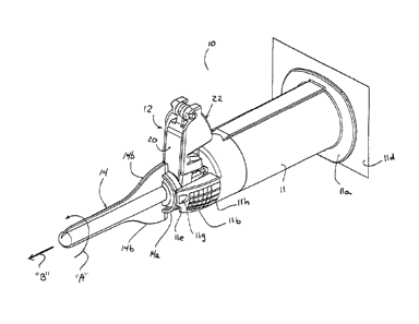
FIG. 1 illustrates a blood collection device 10 having a safety shield
apparatus 12
mounted thereon and a removable sheath 14 positioned about a needle 16 (FIG.
2) of
collection device 10. Blood collection device 10 includes a blood collector
barrel 11 which
7
CA 02647172 2008-09-23
WO 2007/127345 PCT/US2007/010194
defines a cylindrical chamber 18 which is dimensioned to receive a blood
collection vial (not
shown). A proximal end of needle 16 (not shown) is positioned within
cylindrical chamber
18 and is configured to pierce a stopper supported on one end of the blood
collection vial.
As shown in FIGS. IA and 1B, blood collector barrel 11 includes a finger
flange 1 la,
a pair of spaced extensions or towers 1 lb and a nose 11c. Nose 1 lc defines a
throughbore
lid (FIG. 1B) which is dimensioned to receive and frictionally retain needle
16 (FIG. 2)
therein. In one embodiment, finger flange lla is dimensioned or of a size to
facilitate
creation of a positive seal between a proximal face 13 (FIG. 1) of finger
flange 11 a and a
peelable lid lld (FIG. 1) secured to proximal face 13 of finger flange 1 la.
Peelable lid lid
can be secured to finger flange 11 a using an adhesive or the like and can
function to prevent
dust or debris from entering cylindrical chamber 18 or as a sterile barrier
which assures
sterility of cylindrical chamber 18.
Spaced extensions 1 lb are positioned on opposite sides of nose 11c and
include
recesses lie (FIG. 1B) which will be discussed in further detail below. The
inner walls at the
distal end of extensions 11 b define surfaces 11 f for frictionally engaging a
proximal flange
14a of sheath 14 to secure sheath 14 about needle 16. At least one of
extensions llb includes
a land/indentation/depression/recess 1 1 g defining a location where a heated
tool can be
applied to heat stake flange 14a of sheath 14 to at least one of extensions 11
b, thereby
securing sheath 14 to barrel 11. The heat stake provides the clinician with an
indication that
device 10 is new or unused and that sheath 14 has not previously been removed
or tampered
with.
Each extension 1 lb may include fmger gripping sections 11h (FIG. 1) defined
by an
area of ridges, ribs, knurling, roughness, etc. Finger gripping sections 11 h
provide the
clinician with relatively increased gripping, manipulating and holding ability
of blood
collector barrel 11 and, in turn, device 10. Turning momentarily to FIGS. IA
and 1B, in an
alternate embodiment, the outer surface of each extension 1 lb may be smooth
or non-
knurled.
With continued reference to FIG. 1, each extension 1 lb may include a camming
surface, cut-out, recess or the like lie formed in a distal-most corner
thereof. Camming
surface lie functions to aid in the removal of sheath 14 from barrel 11. In
particular, in use,
to remove sheath 14 from barrel 11, sheath 14 is rotated with respect to
barrel 11 (as
8
CA 02647172 2008-09-23
WO 2007/127345 PCT/US2007/010194
indicated by arrow "A" of FIG. 1) until at least one wing or flange 14b of
sheath 14 engages
camming surface lie. Continued rotation of sheath 14 relative to barrel 11, in
the direction
of arrow "A", results in flange(s) 14b camming against a respective camming
surface lie and
the movement of sheath 14 in an axial direction away from barrel 11 (as
indicated by arrow
"B" of FIG. 1) thereby facilitating the separation of sheath 14 from barrel
11. During rotation
of sheath 14 relative to barrel 11, the heat state between flange 14a of
sheath 14 and
extension llb of barrel 11 is broken as a result of shear forces exerted
thereon.
Referring generally to FIGS. 2-7, safety shield apparatus 12 includes a distal
segment
20, a proximal segment 22 and a foot or retention member 24. Distal segment
20, which is
shown in FIGS. 3A, 3B and FIG. 7, includes a body portion 26 having a distal
end 26a and a
proximal end 26b. A hinge member 28 is formed integrally with distal segment
20 at
proximal end 26b thereof. Alternately, hinge member 28 can be formed as a
separate
component from distal segment 20 which is secured thereto. Further, hinge
member 28 can
be formed as a thinned transition region and act as a living hinge which is
integrally formed
between distal segment 20 and proximal segment 22. In this embodiment, hinge
member 28
includes a pair of outwardly directed pivot members 28a which engage a distal
end of
proximal segment 22 to pivotally secure distal segment 20 to proximal segment
22 as will be
discussed in further detail below. Body portion 26 defines a longitudinal
channel 30 which
extends through hinge member 28 along the length of body 26 to a distal wall
32 of distal
segment 20. Channel 30 is dimensioned and configured to receive needle 16
(FIG. 2).
Body portion 26 has an upper wall 34 (FIG. 3B) which extends from proximal end
26b of distal segment towards distal end 26a. Upper wall 34 terminates at an
angled
extension or cowl 36_ In one embodiment, cowl 36 includes a curved distal end
36a and a
proximal end 36b (FIG. 7). While proximal end 36b of cowl 36 is shown as
extending
linearly with distal end 36a, it is contemplated that proximal end 36b need
not extend linearly
from distal end 36a but may extend at an angle with respect to distal end 36a.
Alternatively,
proximal end 36b of cowl 36 may be replaced by any wall (not shown) extending
downwardly from an inner surface of body portion 26 at any location along a
length of body
portion 26. Cowl 36 is positioned to engage and slide along at least one of
nose lie and
needle 16 as safety shield apparatus 12 is moved from a retracted position to
an advanced
position as will be discussed in further detail below.
9
CA 02647172 2008-09-23
WO 2007/127345 PCT/US2007/010194
In one embodiment, body portion 26 also includes a lower wall 38 (FIG. 3A)
positioned at distal end 26a of distal segment 20. A cam or bearing member 40
which
includes an angled surface 40a is formed on lower wall 38. Bearing member 40,
as will be
discussed in further detail below, reduces or minimizes the likelihood of
stalling or binding of
safety shield apparatus 12 in its retracted position. An opening or
throughbore 41 is formed
in distal segment 20 between cowl 36 and lower wall 38.
Referring momentarily to FIGS. 3C and 3D, in an alternate embodiment, a neck
portion 28b, interconnecting body portion 26 and hinge member 28, of distal
segment 20 may
be provided with a strain relief feature in the form of an aperture 28c formed
in a surface
thereof. Aperture 28c may be any suitable geometry including and not limited
to rectangular
(where the longitudinal axis of the aperture is axially aligned with a
longitudinal axis of the
distal segment, or where the longitudinal axis of the aperture is transverse
to the longitudinal
axis of the distal segment), circular, ovular or the like.
Aperture 28c functions as a stress relief hole, wherein aperture 28c is
configured and
dimensioned to cause neck portion 28b to structurally fail prior to pivot
members 28a failing
when forces applied to distal segment 20 exceed a predetermined threshold
level.
Additionally, aperture 28c may be configured and dimensioned to cause neck
portion 28b to
bend prior to pivot members 28a bending when forces applied to distal segment
20 exceed a
predetermined threshold level.
Body portion 26 also includes locking tabs 42 (FIG. 4) and a series of ribs
44.
Locking tabs 42 are positioned on opposite sides of distal segment 20 for
releasably securing
safety shield apparatus 12 in its retracted position as will be discussed
below. Ribs 44
provide rigidity to distal segment 20.
Referring also to FIGS. 5 and 6, proximal segment 22 includes a body 46 having
a
distal end 46a and a proximal end 46b. Body 46 includes a top surface 48 (FIG.
6) and a pair
of spaced sidewalls 50a and 50b. Spaced sidewalls 50a and 50b define a channel
52 which is =
dimensioned to receive distal segment 20 when safety shield apparatus 12 is in
its retracted
position. Channel 52 also allows passage of nose 11 c of blood collection
device 10 and
needle 16. Distal end 46a of proximal segment 22 includes an opening 56 formed
in each
sidewall 50a and 50b. Openings 56 are dimensioned to receive pivot members 28a
of hinge
member 28 (FIG. 3A) to pivotally secure distal segment 20 to proximal segment
22. As
CA 02647172 2008-09-23
WO 2007/127345 PCT/US2007/010194
discussed above, hinge member 28 and openings 56 may be replaced with a living
hinge.
Each sidewall 50a and 50b of proximal segment 22 also includes a cantilevered
tab 58 and a
cutout 60. Cantilevered tabs 58 are positioned to be received within recesses
lie of blood
collection device 10, as will be discussed in further detail below, to lock
safety shield
apparatus 12 in an advanced position. Each cutout 60 is positioned to receive
a respective tab
42 (FIG. 3B) of distal segment 20 to releaseably secure safety shield
apparatus 12 in its
retracted position.
In one embodiment, top surface 48 of body 46 of proximal segment 22 includes a
thumb engagement member 62 which is ribbed to provide a slip-resistant thumb
engaging
surface 64. Sidewalls 50a and 50b also include ribs 65 for providing rigidity
to sidewalls 50a
= and 50b of proximal segment 22.
Retention member 24 is monolithically or integrally formed with proximal
segment
22 and is hingedly connected to proximal end 46b of proximal segment 22 by a
living hinge
66. Alternately, retention member 24 and proximal segment 22 may be formed
separately
and pivotally attached with a separate hinge member. Retention member 24
includes base
portion 68 which defines a mounting hole 70 for securing safety shield
apparatus 12 to blood
collection device 10 as will be discussed in further detail below. Retention
member 24 also
includes a distal wall 72, a proximal wall 74 and a pair of sidewalls 76.
Distal wall 72 is
- integrally connected to living hinge 66 to pivotally secure retention
member 24 to proximal
segment 22. Proximal wall 74 includes a cantilevered extension 77 which
defines a shelf
upon which top surface 40a of bearing member 40 rests when safety shield
apparatus 12 is in
its retracted position. Sidewalls 76 and top and bottom walls 72 and 74 define
a box-like
structure about base portion 68 to provide strength and rigidity to retention
member 24.
Referring momentarily to FIG. 5A, in an alternate embodiment, proximal section
22
may be provided with a rib 76a projecting from a surface of each side wall 76
and extending
in a direction substantially parallel to a central axis of mounting hole. 70.
In use, when
proximal section 22 is secured to blood collector barrel 11, ribs 76a slidably
engage (e.g.,
establish an interference fit with) an inner surface of a respective extension
11 b of blood
collector barrel 11 (see FIGS. 1A and 1B), thereby providing increased
stability
therebetween.
11
CA 02647172 2008-09-23
WO 2007/127345
PCT/US2007/010194
Referring to FIG. 2, in its retracted position, safety shield apparatus 12 is
supported
on blood collection device 10 such that the longitudinal axes of proximal
segment 22 and
distal segment 20 are substantially perpendicular to a longitudinal axis of
needle 16. In the
retracted position of safety shield apparatus 12, tabs 42 of distal segment 20
are releasably
positioned within cutouts 60 of sidewalls 50a and 50b of proximal segment 22
to releasably
lock safety shield apparatus in its retracted position. Further, top surface
40a of bearing
member 40 rests on cantilevered extension 77 of bottom wall 74 of retention
member 24.
Referring to FIG. 8, safety shield apparatus 12 is moved from its retracted
position to
its distal position by manually pressing on thumb engaging surface 64 of
proximal segment
22 in the direction indicated by arrow "A". As illustrated, thumb engaging
surface 64 defines
an angled surface such that pressing on surface 64 creates a force having both
a horizontal
and a vertical component. The vertical component slidably urges top surface
40a of bearing
member 40 onto extension 77 of bottom wall 74 of retention member 24. Since
top surface
40a is angled as illustrated in FIG. 8, engagement between top surface 40a and
extension 77
urges distal end 26a of distal segment 26 outwardly in the direction indicated
by arrows "B".
As this occurs, tabs 42 are forced from cutouts 60, distal end 26a moves
distally along nose
11c of barrel 11 and proximal end 26b of distal segment 20 pivots in relation
to distal end 46a
of proximal segment 22.
=
In the retracted position of safety shield apparatus 12 for the embodiment
shown in
FIGS. 2 and 8, cowl 36 is spaced from nose 11c of blood collector barrel 11
and needle 16.
Alternatively, cowl 36 rests against nose 11c after sheath 14 is removed and
assists slidable
urging of the distal end 26a of distal segment 26 outwardly in the direction
indicated by
arrows "B".
Referring to FIG. 9, as safety shield apparatus 12 is moved in the direction
indicated
by arrow "C" towards its advanced position, top surface 40a of bearing member
14 moves off
of extension 77 and a distal edge 36a of cowl 36 of distal segment 26 moves
into engagement
with needle 16 to guide distal segment 26 along needle 16. As distal segment
26 is moved
further distally, an inwardly extending or proximal portion of cowl 36 moves
along needle 16
until only the proximal edge 36b of cowl 36 engages needle 16 when the safety
shield
apparatus is in its advanced position. See FIG. 10.
12
CA 02647172 2008-09-23
WO 2007/127345
PCT/US2007/010194
As illustrated in FIGS. 11 and 12, as distal segment 26 is moved to its
advanced
position, cantilevered tabs 58 of proximal segment 22 engage an inner wall of
extensions 11 b
of blood collector barrel 11 and are initially deflected outwardly (FIG. 11)
before snapping
into recesses lie of barrel 11 (FIG. 12). Tabs 58 are positioned within
recesses lie to lock
safety shield apparatus 12 in its advanced position. As illustrated in FIG.
10, in the advanced
position of safety shield apparatus 12, needle 16 extends along channel 30
such that distal end
16a of needle 16 is positioned behind distal wall 32 of distal segment 26
adjacent lower wall
38.
FIG. 13 illustrates an alternate embodiment of the presently disclosed safety
shield
apparatus shown generally as 112. Safety shield apparatus 112 is similar to
safety shield
apparatus 12 and includes a distal segment 120, a proximal segment 122 and a
retention
member 124. Proximal segment 122 is pivotally secured to distal segment 120 by
a thinned
transition region or living hinge 126. Safety shield apparatus 112 functions
in a manner
substantially similar to safety shield apparatus 12 discussed above. Thus, the
operation of
safety shield apparatus 112 will not be discussed in detail herein.
FIG. 14 illustrates a retaining collar 140 for mounting safety shield
apparatus 112 to a
blood collection device 110 (See FIGS. 15 and 16). More specifically,
retaining collar 140
includes an annular body 142 having an inner annular portion 142a and an outer
annular
portion 142b joined together by a backspan 142c. Timer annular portion 142a
defines a
diameter dimensioned to be received about a proximal portion of nose 111c of
blood
collection device 110.
In order to mount safety shield apparatus 112 onto blood collection device
110,
retention member 124, which defines an opening 124a (FIG. 13), is positioned
about nose
111c of blood collection device 110 as illustrated in FIGS. 15 and 16. Next,
retaining collar
140 is pressed down over and along nose 111c to capture retention member 124
between
retaining collar 140 and a distal face 111d of blood collection device 110.
The tight
interference fit between the inside diameter of retaining collar 140 and the
outside diameter
of nose 111c provides secure attachment of safety shield apparatus 112 to
blood collection
device 110. It is noted that safety shield apparatus 12 shown in FIGS. 1-12 is
mounted on
blood collector device 10 using a retaining collar 90. See FIGS. 8-10.
Retaining collar 90 is
substantially identical to retaining collar 140.
13
CA 02647172 2008-09-23
WO 2007/127345 PCT/US2007/010194
FIGS. 17-19 illustrate an alternate method and structure for securing a safety
shield
apparatus 212 to a blood collection device 210. More specifically, blood
collection device
210 includes a distal face 210a which includes a plurality of openings 210b.
Retention
member 224 of safety shield apparatus 212 includes a plurality of projections
212a. In one
embodiment, projections 212a include a tapered tip and are dimensioned to be
press fit into
openings 210b to secure safety shield apparatus 212 to blood collector device
210. Although
three openings 210b and three projections 212a are illustrated, it is
envisioned that one or
more openings and projections may be provided, e.g., one, two, four, etc. It
is also
envisioned that the openings may be formed in the retention member and the
projections may
be formed on the blood collection device. As illustrated in FIGS. 17 and 18,
the assembled
device may include a protective sheath 214.
FIGS. 20-22 illustrate yet another method and structure for securing a safety
shield
apparatus 312 to a blood collection device 310. In this embodiment, retention
member 324 of
safety shield apparatus 312 includes an opening 324a which defines one or a
series of annular
recesses and/or ribs or protrusions 330. Nose 311c of blood collector device
310 also
includes one or a series of annular recesses and/or ribs 340 which are
positioned to mate with
annular recesses and/6r ribs 330. In this embodiment, opening 324a defines a
series of
recesses and ribs 330 and nose 311c includes a series of recesses and ribs
340. In order to
mount safety shield apparatus 312 to blood collection device 310, retention
member 324 is
press fit over nose 311c of blood collector device 310 to position recesses
and ribs 330 in
mating alignment with annular recesses and ribs 340. The interference fit
between the
annular ribs and annular recesses provides secure attachment of blood
collection device 310
and safety shield apparatus 312. It is noted that although ribs and recesses
are illustrated as
being smoothly curved other configurations are envisioned, e.g., rectangular
protrusions and
recesses. Further, only recesses may be provided on retention member 324 and
protrusions or
ribs on nose 311c of blood collection device 310, or vice versa. Moreover, the
recesses and
ribs need not be engaged in an interference fit, but rather they may be joined
in an
interlocking fashion.
FIGS. 23-24F illustrate a blood collection device 400 having a safety shield
apparatus
412 mounted thereon and a removable sheath 414 positioned about a needle (not
shown).
Safety shield apparatus 412 of blood collection device 400 is substantially
similar to safety
14
CA 02647172 2008-09-23
WO 2007/127345
PCT/US2007/010194
shield apparatus 112 of blood collection device 110 and thus will only be
discussed in detail
herein to the extent necessary to identify differences in construction and/or
operation thereof.
As seen in FIGS. 23-24F, safety shield apparatus 412 includes a proximal
segment
422 pivotally secured to a distal segment 420 by a thinned transition region
or living hinge
426. Safety shield apparatus 412 functions in a manner substantially similar
to safety shield
apparatus 12 and 112 discussed above.
As best seen in FIGS. 24A and 24C, distal segment 420 includes a raised pad or
the
like 426d projecting from an outer surface of each side wall 426d of body
portion 426.
Raised pads 426d may be disposed beneath or are in registration with locking
tabs 442 of
body portion 426. Raised pads 426d may have a substantially triangular profile
wherein a
wider and/or thicker portion thereof is located closer to the respective
locking tab 442.
Raised pads 426d function to create a frictional engagement with a respective
inner surface of
a side wall 446c of body 446 of proximal segment 422, when safety shield
apparatus 412 is in
a retracted position, as shown in FIG. 23. The degree of friction or
interference between
raised pads 426d against the inner surfaces of side walls 446c of body 446 of
proximal
segment 422 is adjusted based on the dimensions of raised pads 426d (e.g.,
height, width or
thickness) and the distance between side walls 446c of body 446.
As seen in FIG. 24D, distal segment 420 of safety shield apparatus 412
includes a
series of ribs 444 disposed on either side of an inner surface thereof and, in
turn, define
longitudinal channel 430. Longitudinal channel 430 extends through hinge
member 426
along the length of proximal segment 422. Channel 430 is dimensioned and
configured to
receive needle 16 therein (FIG. 2).
As seen in FIGS. 24A-24F, proximal segment 424 of safety shield apparatus 412
includes a rib 476a projecting from a surface of each side wall 476 thereof.
In use, when
proximal section 422 is secured to blood collector barrel 411, ribs 476a are
slidably engage
(e.g., interference fit) an inner surface of a respective extension 411b of
blood collector barrel
411, thereby providing increased stability therebetween.
Turning now to FIG. 25, a hypodermic needle syringe including a safety shield
apparatus, according to an embodiment of the disclosure, is generally
designated 500.
Syringe 500 includes a syringe barrel 502, a plunger rod 504 slidably
disposable within
syringe barrel 502, and a plug 506 selectively supportable on a distal end of
plunger rod 504.
CA 02647172 2008-09-23
WO 2007/127345
PCT/US2007/010194
As seen in FIG. 25, syringe barrel 502 is configured and adapted to support a
safety
shield apparatus 510 on a distal end 502a thereof. Safety shield apparatus 510
may be
constructed and may operate in accordance with any of the safety shield
apparatus' disclosed
herein above. Distal end 502a of syringe barrel 502 is also configured and
adapted to support
a sheath 514 which removably covers a hypodermic needle cannula (not visible).
Syringe
barrel 502 preferably includes graduation marks 530 in milliliters.
Syringe 500 further includes a plunger rod 504 having an elongate plunger
shaft 504a
configured and dimensioned for slidable disposition within a cavity of syringe
barrel 502. A
distal end 504b of plunger shaft 504a may be configured and dimensioned to
support plug
506 thereon. Distal end 504b may include a hub 504c extending distally
therefrom and a pair
of tabs 504d extending radially outwardly from hub 504c.
In one embodiment, plug 506 includes a base wall a pair of spaced apart
uprights 506a
extending from a first surface thereof and defining a space therebetween for
selectively
receiving and engaging tabs 504d of plunger rod 504. Plug 506 may include a
support
element 506b extending from a second surface thereof, opposite the first
surface. Plug 506
further includes a resilient plunger tip 507 supported on support element 506b
thereof.
Plunger tip 507 includes a proximal surface (not shown) configured and adapted
to
selectively engage with support element 506b of plug 506 in a snap-over-type
engagement.
Safety shield apparatus 512 functions in a manner substantially similar to
safety shield
apparatus 12 and 112 discussed above and thus will not be discussed in further
detail herein.
Turning now to FIGS. 26A-26E, a safety shield apparatus, according to another
embodiment of the present disclosure, is shown as 612. Safety shield apparatus
612 is
substantially similar to safety shield apparatus 412 and thus will only be
discussed in detail
herein to the extent necessary to identify differences in construction and/or
operation thereof.
As seen in FIGS. 26A-26E, safety shield apparatus 612 includes a proximal
segment
622 pivotally secured to a distal segment 620 by a thinned transition region
or living hinge
627. Safety shield apparatus 612 functions in a manner substantially similar
to safety shield
apparatus 12,112 and 412 discussed above.
Distal segment 620 includes a body portion 626 having a distal end or wall
626a and a
proximal end or wall 626b. As seen in FIGS. 26A, 26C and 26E, proximal wall
626b is
16
CA 02647172 2014-01-20
sloped or angled with respect to a longitudinal "X" axis of safety shield
apparatus 612. In an
embodiment, proximal wall 626b defines an angled "a" (see FIG. 26C) with
respect to the
longitudinal "X" axis. It is contemplated that angle "a" may be between about
200 and 40 ,
preferably about 30 .
In this manner, when safety shield apparatus 612 is in an extended condition,
if a
force is applied to distal end 626a, in the direction of arrow "F" (e.g.,
transverse to the
longitudinal "X" axis and along a bottom surface of distal segment 620),
distal segment 620
may fold along living hinge 627 until proximal wall 626b contacts a distal
wall 664a of
proximal segment 622.
With continued reference to FIGS. 26A-26E, and in particular, FIGS. 26A, 26B
and
26D, proximal wall 626b of distal segment 626 defines an aperture or window
626c formed
therein and extending completely therethrough.
Aperture 626c functions as a stress relief hole, wherein aperture 626c is
configured
and dimensioned to cause proximal side walls 626d of distal segment 626 to
structurally yield
prior to living hinge 627 failing when forces applied to distal segment 620
exceeds a
predetermined threshold level.
It will be understood that various modifications may be made to the
embodiments
disclosed herein. Although the above description is described in association
with a blood
collection device, it is envisioned that the presently disclosed safety
apparatus and mounting
structure may be used with other medical needle devices, e.g., syringes,
hypodermic needles,
wing-set needles, blood draw needles, etc. Therefore, the above description
should not be
construed as limiting, but merely as exemplifications of preferred
embodiments. Those
skilled in the art will envision other modifications.
17