Note: Descriptions are shown in the official language in which they were submitted.
CA 02647377 2008-09-18
WO 2008/054497 PCT/US2007/008616
SOLAR HEATING BLOCKS
BACKGROUND OF THE INVENTION
1. Field of the Invention
The present invention relates to the field of passive solar energy heating
units which may be installed in building walls in the manner of windows.
2. Description of the Related Art
Passive solar heating units of the subject type are known in the art. For
example, U.S. Patent No. 4,532,917 to Taff et al. shows a modular passive
solar energy
heating unit for heating an enclosed space. The unit employs phase change heat
storage
material, which is optically transparent to visible light when in a high-
stored-energy
liquid state, enabling a viewer to see through clearly, and which is
translucent milky
white when in a low-stored-energy solid state for providing pleasant
illumination to the
enclosed space when first illuminated by sunlight in the morning.
An undesirable characteristic of this and other such modular passive
solar energy heating units of the prior art is their tendency to radiate too
much of the
heat stored during the daylight hours back outside the building at night. As a
consequence, less of the stored heat remains available to heat the building at
night. In
addition, the heat that does remain to be transmitted into the building does
so too
quickly, with the result that its benefit is felt for only a relatively short
time.
The present invention provides a solution to these and other problems of
the prior art.
SUMMARY OF THE INVENTION
Accordingly, the present invention is a solar heating block which is
designed for assembling a solar heating panel in the wall of a building. The
solar
heating block is an insulating, infrared-absorbing, light-diffusing block and
has a top, a
bottom, a first side, a second side, a first face and a second face. The solar
heating
block has an interior volume which includes a first compartment and a second
compartment.
CA 02647377 2008-09-18
WO 2008/054497 PCT/US2007/008616
The first compartment is formed in part by the first face, which is
disposed in use on the outside of the building. The second compartment is
between the
first compartment and the second face. The first compartment contains a
translucent
insulating material, such as an aerogel. The second compartment contains a
heat-
absorbing material, such as water.
In an alternative embodiment, the solar heating block has an interior
volume including first, second and third compartments. The first compartment
is
formed in part by the first face, the second compartment is formed in part by
the second
face and the third compartment is between the first and second compartments.
The first
compartment contains a translucent insulating material, such as an aerogel.
The third
compartment contains a heat-absorbing material, such as water. The second
compartment also contains a heat absorbing material, such as water, where the
solar
heating block is intended for use in a solar heating panel on a side of a
building
exposed to the rays of the sun in the winter, specifically, the south side of
a building in
the northern hemisphere or the north side of a building in the southern
hemisphere. On
the other hand, the second compartment also contains a translucent insulating
material,
such as an aerogel, where the solar heating block is intended for use in a
solar heating
panel on the east or west side of a building.
In a variation of this alternative embodiment, a block intended for use in
a panel substantially unexposed to direct solar radiation at any time of the
year, namely,
a panel on the north side of a building in the northern hemisphere or on the
south side
of a building in the southern hemisphere, the first and second compartments
contain a
translucent insulating material, such as an aerogel, while the third
compartment may
either be empty or filled with a translucent insulating material, such as an
aerogel.
The present invention will now be described in more complete detail,
with frequent reference being made to the figures identified below.
BRIEF DESCRIPTION OF THE DRAWINGS
Figure 1 is an elevational view of a solar heating panel;
Figure 2 is a vertical sectional view taken as indicated in Figure 1;
Figure 3 is horizontal sectional view taken as indicated in Figure 1;
2
CA 02647377 2008-09-18
WO 2008/054497 PCT/US2007/008616
Figure 4 is a perspective view of the left side of the solar heating block
included in the panel of Figure 1;
Figure 5 is a perspective view of the right side of the solar heating block;
Figure 6 is an exploded view of the left side of the solar heating block;
Figure 7 is a vertical cross-sectional view of an alternative embodiment
of the solar heating block;
Figure 8 is a vertical cross-sectional view of still another alternative
embodiment of the solar heating block;
Figure 9 is a vertical cross-sectional view taken through two vertically
stacked solar heating blocks of Figure 8;
Figure 10 is a perspective view of the top surfaces of two adjacent solar
heating blocks of Figure 8;
Figure 11 is a perspective view of alternative top surfaces of two
adjacent solar heating blocks of Figure 8;
Figure 12 is a vertical cross-sectional view through a further
embodiment of the solar heating block;
Figure 13 is a horizontal cross-sectional view through the solar heating
block shown in Figure 12;
Figure 14 is a perspective view of honeycomb material which may be
used in the solar heating blocks of the present invention;
Figure 15 is a vertical cross-sectional view of yet another embodiment
of the solar heating block;
Figure 16 is a vertical cross-sectional view of still another embodiment
of the solar heating block;
Figure 17 is a cross-sectional view through a portion of the solar heating
block of Figure 8 prior to assembly;
Figure 18 is a cross-sectional view through the portion of the solar
heating block shown in Figure 17 following assembly;
Figure 19 is a perspective view of a portion of the solar heating panel of
Figure 1 and a fabric tile;
Figure 20A is a plan view of an alternate fabric tile; and
3
CA 02647377 2008-09-18
WO 2008/054497 PCT/US2007/008616
Figure 20B is a side view of the solar heating panel of Figure 1 showing
the fabric tile of Figure 20A.
DETAILED DESCRIPTION OF THE PREFERRED EMBODIMENTS
Turning now to these figures, Figure 1 is an elevational view of a solar
heating panel 10 assembled from the solar heating blocks 20 of the present
invention.
Such a panel 10 would preferably be installed on the south side of a building
(in the
northern hemisphere) in order to receive maximum exposure to the winter sun,
but
would be at least partly shaded in the summertime by eaves or an overhang. The
view
shown in Figure 1 is one of the panel 10 from inside the building, where the
panel 10
takes the place of a window having southern exposure. The view from outside
the
building, at least in its overall appearance, would be very much the same as
that
presented in Figure 1.
As will be demonstrated below, the solar heating'blocks 20 interlock
with one another to provide some structural integrity to the panel 10 as a
whole. In
addition, the panel 10 is mounted within a frame 22 to ensure a sound
connection to the
wall 24. While a frame is preferred, it is conceivable that the structure
could be
mounted into a wall without a frame.
As shown in Figure 1, the solar heating panel 10 is an array of solar
heating blocks 20 which is six blocks high and eight blocks wide. Of course,
it should
be understood by the reader that the present invention is not limited to
arrays of these
particular dimensions, and that rectangular or square arrays of other
dimensions are
equally possible. Moreover, with appropriate framing, arrays of other shapes
could
alternatively be constructed.
Figure 2 is a vertical section through one of the solar heating blocks 20
of panel 10, and partly showing the block 20 immediately thereabove, taken as
indicated in Figure 1. The solar heating block 20 comprises a block body 26
having a
first block body half 28 and a second block body half 30. The block body
halves 28, 30
are molded from clear or translucent plastic, such as an acrylic plastic, and
heat-welded
or sealed together to produce a watertight connection.
4
CA 02647377 2008-09-18
WO 2008/054497 PCT/US2007/008616
On the left-hand side of the block 20 in Figure 2, that is, the side of the
block 20 on the outside of the building, is a lens 32, which is also molded
from clear or
translucent plastic, such as an acrylic plastic or other material having high
solar
transmission. The lens 32, having approximately the same height and width
dimensions as the block 20, is heat-welded or sealed to face 34 of the first
block body
half 28 at notch 36 which runs around the perimeter thereof. The lens 32 is
about 1.0
inch deep, and provides a volume that thick and of the height and width
dimensions of
the block body 26 outwardly of face 34 for a translucent insulating material
38.
The purpose of translucent insulating material 38 is to prevent heat
stored in the solar heating block 20 during the daylight hours from radiating
outward
during the nighttime hours. In addition, the translucent insulating material
38 allows
solar radiation from outside the building to pass through the solar heating
blocks 20 to
provide natural illumination to the interior of the building and to heat the
material
within the block body halves 28, 30.
The translucent insulating material 38 of choice is aerogel, a unique
form of highly porous non-hazardous silica having a lattice network of glass
strands
with very small pores. The solids content of aerogel is extremely low (5%
solid, 95%
air). Aerogel is recognized to be one of the most lightweight and best
insulating solids
in the world. An aerogel highly suited for the practice of the present
invention is
available from Cabot Corporation of Billerica, Massachusetts under the name
NANOGEL . These aerogels are produced in a method which renders them
hydrophobic with the result that they repel water which otherwise tends to
degrade its
component particles, which are generally in a size range from 0.5 mm to 4.0
mm.
The block body 26, itself is filled with water 40, except for a small
volume 42 at the top to allow for expansion. Three inches of pure, or clear,
water
absorbs about an estimated 50% of the solar infrared radiation passing through
the
block body 26 which generally provides a water thickness in a range from 3.0
to 6.0
inches. Several means are available for increasing this percentage. For
example, the
water may be dyed with a variety of coloring agents used for this purpose to
increase
the estimated absorption to the range of 70% to 85%. Alternatively, a
dispersion agent
may be used to color the water white or some other hue. The water may also
include
5
CA 02647377 2008-09-18
WO 2008/054497 PCT/US2007/008616
antifreeze and antimicrobial agents. For example, the water may include table
salt
(sodium chloride) or calcium chloride, which function both as antifreeze and
antimicrobial agents. In addition, distilled water may be used to minimize the
mineral
and microbial content of the water being used to fill the block body 26.
Finally, by
filling the block body 26 with hot water, or with water that has been
previously been
deaerated or degassed, the formation of bubbles on the inner surface of the
block body
26 and the amount of air or gas in small volume 42 at the top of the block
body 26 may
be kept to a minimum.
The water 40, with or without a coloring agent, could be placed into the
fonm of a gel through the addition of a small amount of a gelling agent, such
as
methylcellulose. The benefits of the gelling agent are that it prevents a
spill should the
block body 26 crack or break, and it inhibits convective flow within the block
body 26.
The latter would permit heat to be transmitted more quickly from the water
into the
building. Water 40 having the gelling agent added tends to hold on to stored
heat for a
longer period of time. A minimal amount of gelling agent is all that is
required; too
much tends to turn the water 40 into an opaque mass.
Alternatively, so-called phase-change materials could be used in place of
water. Such materials take advantage of the heat absorbed or released by a
material
when changing from one state to another, such as from a solid to a liquid
(melting) or
vice versa (freezing) at constant temperature, and enable a greater amount of
heat to be
stored in the solar heating block 20 when the phase-change material is heated
through a
temperature range which includes the temperature at which the phase-change
occurs.
Polyethylene glycol, as disclosed in U.S. Patent No. 4,532,917 to Taff et al.
noted
above, is a phase-change material that may be used for this purpose. Many
others are
known to those of ordinary skill in the art.
As noted above, the block body 26 generally provides a water thickness
in a range from 3.0 to 6.0 inches. The block body 26 itself may be generally
square,
perhaps 8.0 to 12.0 inches on a side, although it need not be perfectly
square. On a
practical level, however, the fact that the block 20 may become overly heavy
and
unwieldy if made too large, as well as generating a large hydrostatic pressure
which
6
CA 02647377 2008-09-18
WO 2008/054497 PCT/US2007/008616
could more easily result in a leak, makes sizes at the smaller end of the
stated range
more preferable.
The inner face 44 of the block body 26 may be clear, frosted or
patterned, as desired, to provide a suitable interior finish. Further, in the
view provided
in Figure 2, the top and bottom of the preferred block body 26 include means
by which
the solar heating blocks 20 may be stacked upon one another. Specifically, the
bottom
of the block body 26 has feet 46, 47, while the top has a narrowed portion 48
creating
volume 42 provided for expansion, foot 46 being a continuation of face 34.
Feet 46,
47, which run the width of the block body 26, straddle the narrowed portion 48
and
thereby provide a stable stacking arrangement. Weather strip 50 runs between
the outer
foot 46 of the block body 26 above and the narrowed portion 48 for the width
of the
block body 26 and down one of its two sides - weather strip 50 on its
neighbors
providing for the bottom and the other of the two sides. Gap 52 between solar
heating
blocks 20 on the exterior of the building may be as little as 1/32 inch
(0.03125 inch).
Figure 3 is a horizontal section through another of the solar heating
blocks 20 of panel 10, and partly showing the block 20 immediately to its
right, taken
as indicated in Figure 1. Much of the detail shown in Figure 3 has been
described
above, and the previously used drawing reference numerals have been inserted
where
appropriate.
As the top and bottom of the block body 26 includes means by which the
solar heating blocks 20 may be stacked upon one another, so also the left and
right
sides of the block body 26, as viewed in Figure 3, include means by which the
solar
heating blocks 20 may be connected to their neighbors on the left and right.
Referring
first to the left-hand side of block body 26 in Figure 3, struts 54, 56 extend
from the left
side of the block body 26, strut 54 being a continuation of face 34, and abut
against the
right side of a block body 26 to its left. Between struts 54, 56, which run
for the full
height of the block bodies 26, are interlock legs 58. As will be seen below,
interlock
legs 58, of which there are two, one above the other, on the left-hand side of
the block
body 26, do not extend for the full height thereof, and do not extend as far
laterally
from the left-hand side of the block body 26 as the struts 54, 56.
7
CA 02647377 2008-09-18
WO 2008/054497 PCT/US2007/008616
On the right-hand side of the block body 26 is a narrowed portion 60
which fits between strut 54 and interlock legs 58 of the block body 26 to its
right.
Nanrowed portion 60 includes wedges 62, of which there are two, as will be
seen
below. Wedges 62, which also do not run for the full height of the block body
26, mate
with interlock legs 58 to hold the block bodies 26 together. Weather strip 50
runs down
one side of block body 26 between strut 54 and narrowed portion 60.
Figure 4 is a perspective view of the left side of the solar heating block
20. First block body half 28 and second block body half 30 are heat-welded or
sealed
together along joint 64 to produce a watertight connection. Weather strip 50
runs along
the top of block body 26 along narrowed portion 48. Struts 54, 56 extend from
the left
side of the block body 26, and continue around the bottom where they become
feet 46,
47. The surfaces of foot 46 and strut 54 ultimately abut against the weather
strips 50 on
adjacent solar heating blocks 20 below and to the left of that illustrated.
Interlock legs 58 extend outwardly one above the other from the left side
of the block body 26. The lower of the two interlock legs 58 extends downward
like
feet 46, 47 to fit between the gap between two solar heating blocks 20
disposed below,
specifically between the narrowed portions 48 thereof to line the blocks 20 up
in a
vertical direction.
Figure 5 is a perspective view of the right side of the solar heating block
20. Weather strip 50 runs, as stated above, along narrowed portion 48 on the
top of
block body 26, and down narrowed portion 60 on the right side of block body
26.
Wedges 62 having inclined surfaces 66 oriented inwardly toward block body 26
mate
with interlock legs 58 of a neighboring solar heating block 20. As such a
block 20 is so
mated, inclined surfaces 66 bring the two blocks 20 into a tight side-by-side
relationship.
Figure 6 is an exploded view of the exterior of the left side of the solar
heating block 20 as shown in Figure 4. Lens 32 is shown as being separated
from face
34 of block body 26, where it is ordinarily heat-welded or sealed to notch 36.
In order
to increase the amount of thermal energy being absorbed by the contents of the
block
body 26, as an alternative or in addition to dyeing the water or using a phase-
change
8
CA 02647377 2008-09-18
WO 2008/054497 PCT/US2007/008616
material, the face 34 may be provided with dots or squares 68, which may cover
50% to
80% of the area of face 34.
The squares 68 or, alternatively, dots or figures of some other shape, are
arranged in an array on face 34, as shown in Figure 6. The squares 68 are
first applied
using white or another light-colored paint. Subsequently, the white squares 68
are
covered in flat black paint or paint of some other absorbing color. With the
face 34
patterned in this manner, the black surface of the squares 68 on the outside
of the face
34 absorbs more heat energy and allows it to be conducted inwardly to warm the
contents of the block body 26. The white or light inside surface of the
squares 68
reflects heat from within the block body 26 back therein to reduce heat loss.
Between
the squares 68, the face 34 is clear or translucent so that some light is able
to pass
through and provide natural illumination within the building.
In an alternative embodiment of the solar heating block of the present
invention, shown in a cross-sectional view in Figure 7, solar heating block 70
has a
block body 72 in the form of a glass block. Glass blocks of this type are
available in 8"
x 8" x 4" and 12" x 12" x 4" sizes, although a 6.0-inch thickness would be
more
desirable in the present context.
The block body 72 includes a first block body half 74 and a second
block body half 76 which are produced separately and joined to one another at
seam 78.
At the top, a hole is drilled for use in filling the block body 72 with water
80, or other
heat-absorbing material, leaving an air space 82 at the top for expansion. A
stopper 84
or sealant is then used to close the hole once the block body 72 is filled.
The inside face 86 of the block body 72 may preferably be frosted or
otherwise light-diffusing, while the outside face 88 may be patterned with an
array of
squares or other shapes, as described above, to maximize heat absorption. An
outer
pane 90 of low-iron glass, preferably having a thickness of 0.125 inches, is
attached to
the outside face 88 using a plastic separator extrusion 92 to minimize heat
loss outward
from the glass block body 72, and to create a volume, preferably having a
thickness of
1.0 inches, for a translucent insulating material 94, such as an aerogel
material, as
described above. The plastic separator extrusion 92 is sealed to the block
body 72 and
9
CA 02647377 2008-09-18
WO 2008/054497 PCT/US2007/008616
outer pane 90. The 1.0-inch thickness of aerogel provides an R-value of 8.0,
offering a
high resistance to heat flow from within the block body 72.
The glass block body 72 and pane 90 represent an attempt to make a
more durable solar heating block 70 than that previously described. However,
the glass
solar heating block 70 may have to be deployed differently than is currently
the case,
because mortar used to cement the blocks 70 to one another may provide a path,
also
known as a "thermal short", for heat to escape outwardly from within the block
70. In
order to avoid such an outcome, individual solar heating blocks 70 may have to
be
separated from one another by plastic strips, and grouting or mortar may have
to be
used only where it is not able to conduct heat from the block body 72 to the
exterior of
the building.
In still another alternative embodiment of the solar heating block of the
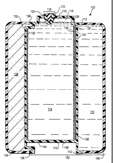
present invention, shown in a cross-sectional view in Figure 8, solar heating
block 100
has a block body 102 which includes three sections, namely, a first interior
block body
half 104, a second interior block body half 106, and an inner lens 108, the
latter being
so-called because it is inside a building when solar heating block 100 is in
use as
intended. The first interior block body half 104 and the second interior block
body half
106 are bonded to one another along joint 110, and the inner lens 108 is
bonded to the
second interior block body half 106 along joint 112.
The first interior block body half 104, the second interior block body
half 106, and the inner lens 108 are molded from clear or translucent plastic,
such as an
acrylic plastic, and heat-welded or sealed along joints 110, 112 to produce
watertight
connections. Water 114, or other heat absorbing material, fills the interior
of the block
body 102, that is say, filling the volume between the first interior block
body half 104
and the second interior block body half 106, except for an air space 116 at
the top
allowing for expansion, as well as the volume between the second interior
block body
half 106 and the inner lens 108. The water 114, or other heat-absorbing
material, is
introduced through hole 118, which is subsequently closed with a plug 120 and
a
wedge 122, which lastly is inserted into the center of plug 20 and forced
thereinto to
ensure that the plug 120 makes an airtight seal in hole 118.
CA 02647377 2008-09-18
WO 2008/054497 PCT/US2007/008616
It will be observed that the block body 102 has an internal wall 124,
which is physically part of the second interior block body half 106 and which
separates
the two compartments formed by the first interior block body half 104 and the
second
interior block body half 106 and by the second interior block body half 106
and the
inner lens 108. Internal wall 124 includes holes 126 so that water 114, or
other heat-
absorbing material, will pass into the compartment between the second interior
block
body half 106 and the inner lens 108 when introduced through hole 118 and will
completely fill that compartment, leaving no air trapped therewithin.
Internal wall 124 is preferably frosted, ensuring that it is translucent
rather than transparent, for reasons to be explained more fully below.
Alternatively, a
diffuser plate 128 of frosted glass or plastic, may disposed adjacent to
internal wall 124
within the compartment formed between the first interior block body half 104
and the
second interior block body half 106 for the same purpose. As above, inner lens
108
may be clear, frosted or patterned, as desired, to provide a suitable interior
finish.
A heat-absorbing grid 130 is disposed adjacent to outer wall 132 of first
interior block body half 104 and within the water-filled compartment formed
between
the first interior block body half 104 and the second interior block body half
106.
Alternatively, and preferably, the heat-absorbing grid 130 is disposed
adjacent to, or is
physically joined to or is combined with, diffuser plate 128. Heat-absorbing
grid 130
has the same purpose as squares 68 described above, that is, it increases the
amount of
thermal energy being absorbed by the contents of the block body 102. In the
present
embodiment, the heat-absorbing grid 130 is a perforated plate which is black
on one
side and white, or some other light color, on the other side. The perforations
take up
from 20% to 50% of the area of the heat-absorbing grid 130 so that the area
not
represented by the perforations is from 50% to 80% of the total area thereof.
As before,
the heat-absorbing grid is oriented so that the black side faces outwardly
toward the
exterior of the building when solar heating block 100 is in use, while the
white or light
side faces inwardly toward the interior of the building.
On the left-hand side of the solar heating block 100 in Figure 8, which
will be the side of the block 100 on the outside of the building is an outer
lens 134,
which is also molded from clear or translucent plastic, such as an acrylic
plastic or
11
CA 02647377 2008-09-18
WO 2008/054497 PCT/US2007/008616
other material having high solar transmission. The outer lens 134 is heat-
welded or
sealed to first interior block body half 104 at joint 136. Translucent
insulating material
138 is disposed in the volume between the outer lens 134 and outer wall 132 of
first
interior block body half 104. Preferably, the translucent insulating material
138 is an
aerogel material, as described above.
Figure 9 is a cross-sectional view taken through two vertically stacked
solar heating blocks 100, as they would be used in a solar heating panel 10.
Between
the vertically stacked solar heating blocks 100 is a bar 140, preferably of
steel, which
runs from one side of frame 22 to the other to provide the solar heating panel
with
additional strength and stability. Bar 140 may have cross-sectional dimensions
of
0.125 inch by 1.5 inch. However, as will be realized by one of ordinary skill
in the art,
bars 140 would tend to be apparent to an observer viewing the solar heating
panel from
within a building as dark lines running horizontally across the solar heating
panel 10.
This effect is minimized or completely eliminated by the diffuser plates 128
in the
vertically stacked solar heating blocks 100. The diffuser plates 128 scatter
light passing
through the solar heating blocks 100 from left to right in Figure 9, that is,
from outside
to inside the building, in all directions. In this manner, light is scattered
around the
opaque bar 140 making the presence of the bar 140 less apparent to an observer
in the
building. It should also be noted that air space 116 is hidden from the view
of an
observer on either side of the stacked solar heating blocks 100.
Gaskets 142 separate the outer lenses 134 and the inner lenses 108 of
adjacent solar heating blocks 100 to prevent thermal shorts and to eliminate
drafts
which would compromise the functioning of the solar heating panel 10
comprising
solar heating blocks 100.
Figure 10 is perspective view of the tops of two adjacent solar heating
blocks 100 showing their connections to one another for additional support and
stability. The sides of the first interior block body half 104 and the second
interior
block body half 106 have vertically oriented spacing ribs 144 to provide a
slight gap
146 between laterally adjacent blocks 100. On each side of the blocks 100 is a
slot 148,
those on the adjacent blocks 100 lining up with one another to produce a
generally U-
shaped combined slot. Connector 150, adapted to fit into the combined slot and
having
12
CA 02647377 2008-09-18
WO 2008/054497 PCT/US2007/008616
inclined surfaces, draws the blocks 100 into a tight relationship as it is
forced down into
the combined slots 148. Bar 140 fits between the two connectors, 150, and the
next
horizontal row of solar heating blocks sit on top of the connectors 150 below.
Figure 11 is a perspective view of the tops of two adjacent solar heating
blocks 100 showing an alternate approach for connecting them to one another.
In this
alternate approach, the connectors are generally H-shaped having vertical legs
which
gradually narrow from the horizontal cross member to their tops and bottoms.
Again,
on each side of the blocks 100 is a slot 152, those on adjacent blocks 100
lining up with
one another. As show in Figure 11, the connectors 154 have horizontal cross
members
156 which maintain a desired separation between adjacent solar heating blocks,
although vertically oriented spacing ribs may also be present. The legs 158 of
the
connectors 154 are inserted into slots 152 and draw the adjacent solar heating
blocks
100 into a tight lateral relationship with one another. As above, connectors
154
straddle bar 140, and the next horizontal row of solar heating blocks 100,
which have
slots 152 on their undersides, sit on top of the connectors 154 below.
In general, the solar heating blocks of the present invention provide day
lighting to the interior of a building in which they are used and, as such, it
may be
desirable to use them as east-, west- and north-facing (or south-facing in the
southern
hemisphere) windows as well as in the south-facing walls (in the northern
hemisphere)
for which they are primarily designed. Their use in east- or west-facing
walls,
however, will lead to overheating in summer, as they would receive the direct
summer
sun. However, with an array of white squares used instead of the black ones
described
above, most of the thermal radiation will be reflected back outside without
passing
through the solar heating block. This will permit the same day lighting to be
achieved
as in the previously described south-facing system without overheating. More
sophisticated solar reflection systems may alternatively be used instead of
the white
squares described above.
Winter solar heat gain would not be required in east-, west- and north-
facing walls. As a consequence, a less sophisticated translucent insulation
material
than aerogel, such as white fiberglass or fumed silica, could be used in solar
heating
blocks for those walls.
13
CA 02647377 2008-09-18
WO 2008/054497 PCT/US2007/008616
For example, and referring to the embodiment shown in Figure 8, south-
facing walls (or north-facing walls in the southern hemisphere) would include
the solar
heating block 100 as described above. For east-and west-facing walls, holes
126 would
not be provided so that aerogel material could be disposed between both the
outer lens
134 and the first interior block body half 104 and the second interior block
body half
106 and inner lens 108. Water, or other heat-absorbing material, would then
fill only
the compartment between the first interior block body half 104 and the second
interior
block body half 106. Heat could than be stored in that interior compartment
and
subsequently vented to the outside of the building, perhaps with the
assistance of a
temperature-controlled fan to pass air through the spaces between adjacent
blocks.
For north-facing walls (or south-facing walls in the southern
hemisphere), the water would be omitted from the compartment between the first
interior block body half 104 and the second interior block body half 106,
leaving this
compartment empty. Alternatively, this compartment, too, could also be filled
with
aerogel material.
One problem with aerogel material, however, is its tendency to settle
over the course of time in response to vibrations and other movements, as
aerogel tends
to settle as its constituent pellets achieve ideal packing. For this reason,
it is not
currently used between sealed glass insulating panels, because settling would
leave a
large gap at the top of the panel. In the present invention, the relatively
small height of
the solar heating blocks reduces the scale of the settling and permits it to
be hidden or
otherwise addressed more simply.
Referring now to Figure 12, a cross-sectional view through a solar
heating block 200 taken in the same manner as shown in Figure 2, specifically,
taken in
a vertical direction and looking toward the right side of the panel as
illustrated in Figure
1. In solar heating block 200, lens 202 is sealed to the outer face 204 of the
block body
206. Translucent insulating material 208 may settle as indicated by the
presence of
space 210 at the top of the volume between the lens 202 and outer face 204 of
block
body 206. As before, the outer face 204 may be patterned with an array of heat-
absorbing squares as previously described.
14
CA 02647377 2008-09-18
WO 2008/054497 PCT/US2007/008616
It will be noted that the upper and lower surfaces of lens 202 are inclined
in a downward direction. As a consequence, space 210, from which translucent
insulating material 208 has settled, is hidden from view by the lens 202 of
the solar
heating block 200 immediately above. At the same time, air space 212 at the
top of
block body 206 is also hidden from view.
The same approach may also be used on the inside of the solar heating
block 200. Block body 206 may comprise a first block body half 214 and a
second
block body half 216, which may be physically identical to lens 202. First
block body
half 214 and second block body half 216 may be hermetically welded or sealed
to one
another along sea1218. Second block body half 216, like lens 202, has upper
and lower
surfaces which are inclined in a downward direction. As a consequence, the air
space
212 is hidden from view by the second block body half 216 of the solar heating
block
200 immediately above. Weather strip 220 may be used as shown between the
lenses
202 and second block body halves 216 of the vertically stacked solar heating
blocks
200.
Figure 13 is a cross-sectional view through solar heating block 200
taken in the same manner as shown in Figure 3, specifically, taken in a
horizontal
direction and looking downward in the panel as illustrated in Figure 1.
Referring to
Figure 13, solar heating block 200 interlocks with those on its left and right
in a manner
similar to that shown in Figure 3. Specifically, a pair of interlock legs 222
are on one
side of block body 206 while a pair of wedges 224, similar to those previously
described above, interlock with one another to hold solar heating block 200
securely to
its neighbors on either side. At the bottom of the block body 206, interlock
legs 222
extend downward into the space between the neighboring blocks 200 below to
align the
blocks 200 vertically.
In an alternative approach, a honeycomb material 230, shown in a
perspective view in Figure 14, of appropriate dimensions may be disposed
between lens
32 and face 34 of block body 26, such that the individual cells 232 are
oriented in a
horizontal direction. The honeycomb material 230 may, for example, be of a
clear
Mylar, and may be placed in lens 32 with the individual cells 232 oriented in
a vertical
direction. Translucent insulating material 234, such as aerogel, may then be
poured
CA 02647377 2008-09-18
WO 2008/054497 PCT/US2007/008616
into cells 232 to completely fill them. After the translucent insulating
material 234 is
leveled, and the block body 26 attached to the lens 32, any settling of the
translucent
insulating material 234 within the individual cells 232 will be far less
noticeable than it
would have been without the honeycomb material 230.
In yet another approach, shown in vertical cross section in Figure 15, a
solar heating block 240 includes an absorber plate 242 having an array of
absorbing
squares as described above. Between the absorber plate 242 and the outside of
the solar
heating block 240 is translucent insulating material 244, such as aerogel. On
the inside
of the absorber plate 242, the liquid contents which absorb heat are sealed
within a
plastic bag 246, or the like, which maintains pressure on the absorber plate
242. Any
settling of the translucent insulating material 244 is rendered less apparent
by the
pressure on absorber plate 242 causing the translucent insulating material 244
to
continue to fill the space between the absorber plate 242 and the outside of
the solar
heating block 240. The inside of the solar heating block 240 includes limit
stops 248
which limit the extent the absorber plate 242 may move toward the outside of
the block
240. The block 240 may also be open at vent 250 to allow for expansion. In
addition,
the absorber plate 242 may be eliminated and the absorbent array of squares
printed
directly on plastic bag 246 in an alternative arrangement. Solar heating block
240 may,
in this embodiment, be a clear plastic (acrylic) block.
In still another approach, shown in vertical cross section in Figure 16,
solar heating block 256 includes a separate, interior liquid container 258,
which may be
blow-molded, filled with liquid and sealed, leaving air space 260 for
expansion. Outer
face 262 of liquid container 258 may be provided with an array of absorbent
squares, as
previously described.
On the outside of the liquid container 258 is translucent insulating
material 264, such as aerogel, occupying the space between the liquid
container 258
and the outside of the solar heating block 256. On the other side of the
liquid container
258 within the solar heating block 256. is an air space 266 which has some
insulating
value to slow the transfer of heat from the contents of the liquid container
258 to the
interior of the building. Springs 268 bias the liquid container 258 toward the
translucent insulating material 264 to negate any settling which may take
place therein.
16
CA 02647377 2008-09-18
WO 2008/054497 PCT/US2007/008616
The inside face 270 of the solar heating block 256 may be of a light-diffusing
character,
for example, frosted.
Finally, the embodiment shown in Figure 8 enables still another
approach toward solving the settling problem to be taken. Referring to Figure
17, a
cross-sectional view of first interior block body half 104 and outer lens 134
before they
are joined to one another, it will be noted that outer wall 132 of first
interior block body
half 104 protrudes beyond edges 160, which are heat-welded or sealed to edges
162 of
outer lens 134 to produce joint 162 of outer lens 134 to produce joint 136.
The amount
of protrusion is labeled "X" in Figure 17.
Translucent insulating material 138, such as an aerogel material, is
disposed in outer lens 134 to a depth an amount "Y" below edges 162. By
filling the
outer lens 134 to a depth such that "Y" is less than "X", the translucent
insulating
material 138 is compressed by outer wall 132 to some degree when the first
interior
block body half 104 is forced down thereonto to bring edges 160 into contact
with
edges 162 to permit joint 136 to be formed. The result is shown in Figure 18,
where the
translucent insulating material 138 occupies the entire volume between the
first interior
block body half 104 and the outer lens 134.
The compression of the translucent insulating material 138 has been
found to cure the settling problem by packing it into the available volume. In
the
compressed state each particle of the translucent insulating material 138
becomes
locked into position relative to others to prevent settling from occurring. It
has been
found that an amount of compression, which equals "X-Y", equal to about 20% of
the
original uncompressed depth of the translucent insulating material 138 in the
outer lens
134 solves the settling problem completely.
Returning, now, to the view presented in Figure 1, it may be desirable to
install insulating fabric tiles on the inside surfaces of the solar heating
blocks 20 shown.
Such fabric tiles may be useful to moderate the rate at which solar heating
blocks 20
release stored heat into the room, as well as to provide an aesthetic visual
appearance
and to allow consumers to coordinate the appearance of the entire solar
heating panel
10 with the rest of the room. A felt insulating pad, light-transmitting, and
having
desired thicknesses and numbers of layers, can be trapped by the fabric tile
to provide
17
CA 02647377 2008-09-18
WO 2008/054497 PCT/US2007/008616
varying degrees of insulation to temper the system to achieve a desired R
value, such as
R-1 to R-3. A higher R value on the inside, while still not approaching R-8 of
aerogel
material, still allows a majority of the stored heat to flow towards the room,
but tempers
its flow and allows the temperature of water in the blocks 20 to remain hotter
and to
heat the room for a longer period of time.
Figure 19 is a perspective view of a portion of the solar heating panel 10
shown in Figure 1 showing the installation of a fabric tile 280 on one of the
solar
heating blocks 20. Trim 282, which may be of wood or plastic, snaps into the
gaps
between adjacent solar heating blocks 20 to hold the fabric tile 280 in place.
The
optional translucent felt insulating pad 284, when desired, is installed
behind the fabric
tile 280.
In an alternate embodiment, shown in Figures 20A and 20B, fabric tile
286 has the flattened appearance shown in the plan view of Figure 20A with
creases
288. When folded along the creases 288, the fabric tile 286 is installed in
the gaps
between adjacent solar heating blocks 20, as shown in side view in Figure 20B.
The
optional translucent felt insulating pad 290, when desired, is installed
behind the fabric
tile 286.
It should be appreciated that a framed window consisting of multiple
blocks may use blocks having different degrees of translucency and heat
absorption.
These blocks could include a transparent block filled with water using an air
space as
insulation, a transparent or translucent block filled with water using aerogel
as an
insulation, and a transparent or opaque block filled with phase-change
material using
aerogel as insulation, or any combination thereof. This provides for privacy
with some
see-through and balances the energy differences between an air-insulated
transparent
water block and an aerogel-insulated semi-opaque phase-change block, thus
creating a
window system which, as a whole, is very energy efficient.
Modifications to the above would be obvious to those of ordinary skill in
the art, but would not bring the invention so modified beyond the scope of the
appended claims.
18