Note: Descriptions are shown in the official language in which they were submitted.
CA 02647385 2013-07-03
ENERGY COLLECTION SYSTEM USING A COLLECTION DEVICE
SUSPENDED FROM A SUPPORT STRUCTURE
TECHNICAL FIELD
The present disclosure is generally related to energy and, more particularly,
is
related to systems and methods for collecting energy.
BACKGROUND
The concept of fair weather electricity deals with the electric field and the
electric
current in the atmosphere propagated by the conductivity of the air. Clear,
calm air carries
an electrical current, which is the return path for thousands of lightening
storms
simultaneously occurring at any given moment around the earth. For simplicity,
this
energy may be referred to as static electricity or static energy. FIG. 1
illustrates a weather
circuit for returning the current from lightning, for example, back to ground
10. Weather
currents 20, 30 return the cloud to ground current 40.
In a lightening storm, an electrical charge is built up, and electrons arc
across a
gas, ionizing it and producing the lightening flash. As one of ordinary skill
in the art
understands, the complete circuit requires a return path for the lightening
flash. The
atmosphere is the return path for the circuit. The electric field due to the
atmospheric
return path is relatively weak at any given point because the energy of
thousands of
electrical storms across the planet are diffused over the atmosphere of the
entire Earth
during both fair and stormy weather. Other contributing factors to electric
current being
present in the atmosphere may include cosmic rays penetrating and interacting
with the
earth's atmosphere, and also the migration of ions, as well as other effects
yet to be fully
studied.
Some of the ionization in the lower atmosphere is caused by airborne
radioactive
substances, primarily radon. In most places of the world, ions are formed at a
rate of 5-10
pairs per cubic centimeter per second at sea level. With increasing altitude,
cosmic
radiation causes the ion production rate to increase. In areas with high radon
exhalation
from the soil (or building materials), the rate may be much higher.
1
CA 02647385 2008-09-25
WO 2007/098341
PCT/US2007/062114
Alpha-active materials are primarily responsible for the atmospheric
ionization.
Each alpha particle (for instance, from a decaying radon atom) will, over its
range of some
centimeters, create approximately 150,000-200,000 ion pairs.
While there is a large amount of usable energy available in the atmosphere, a
method or apparatus for efficiently collecting that energy has not been
forthcoming.
Therefore, a heretofore unaddressed need exists in the industry to address the
aforementioned deficiencies and inadequacies.
SUMMARY
Embodiments of the present disclosure provide systems and methods for
collecting energy. Briefly described in architecture, one embodiment of -the
system,
among others, can be implemented by a support structure wire elevated above a
ground
level, at least one collection fiber electrically connected tò the support
structure wire; a
load electrically connected to the support structure wire; and a diode
electrically connected
between the load and at least one collection fiber.
[0002] Embodiments of the present disclosure can also be viewed as
providing methods
for collecting energy. In this regard, one embodiment of such a method, among
others,
can be broadly summarized by the following steps: suspending at least one
collection
fiber from a support structure wire elevated above ground level, the fiber
electrically
connected to the support structure wire; providing a load with an electrical
connection to
the support structure wire to draw current; and providing a diode electrically
connected
between the collection fiber and the load.
[0003] Other systems, methods, features, and advantages of the present
disclosure will be
or become apparent to one with skill in the art upon examination of the
following
drawings and detailed description. It is intended that all such additional
systems,
methods, features, and advantages be included within this description, be
within the scope
of the present disclosure, and be protected by the accompanying claims.
2
CA 02647385 2008-09-25
WO 2007/098341
PCT/US2007/062114
BRIEF DESCRIPTION OF THE DRAWINGS
[0004] Many aspects of the disclosure can be better understood with
reference to the
following drawings. The components in the drawings are not necessarily to
scale,
emphasis instead being placed upon clearly illustrating the principles of the
present
disclosure. Moreover, in the drawings, like reference numerals designate
corresponding
parts throughout the several views.
[0005] FIG.1 is a circuit diagram of a weather energy circuit.
[0006] FIG. 2 is a perspective view of an exemplary embodiment of many
energy
collectors elevated above ground by a structure.
[0007] FIG. 2A is a side view of an energy collection fiber suspended
from a support
wire.
[0008]. FIG. 2B is a side view of an exemplary embodiment of an energy
collection fiber
suspended from a support wire and with an additional support member.
[0009] FIG. 2C is a perspective view of a support structure for
multiple energy collection
fibers.
[0010] FIG. 2D is a side view of an exemplary embodiment of a support
structure for
multiple energy collection fibers.
[0011] FIG. 2E is a side view of a support structure for an energy
collection fiber.
[0012] FIG. 2F is a side view of an exemplary embodiment of a support
structure for an
energy collection fiber.
[0013] FIG. 2G is a side view of a support structure for multiple
energy collection fibers.
[0014] FIG. 3 is a circuit diagram of an exemplary embodiment of a
circuit for the
collection of energy.
[0015] FIG. 4 is a circuit diagram of an exemplary embodiment of a
circuit for the
collection of energy.
[0016] FIG. 5 is a circuit diagram of an exemplary embodiment of an
energy collection
circuit for powering a generator and motor.
[0017] FIG. 6 is a circuit diagram of an exemplary embodiment of a
circuit for collecting
energy and using it for the production of hydrogen and oxygen.
3
CA 02647385 2008-09-25
WO 2007/098341
PCT/US2007/062114
[0018] FIG. 7 is a circuit diagram of an exemplary embodiment of a
circuit for collecting
energy, and using it for driving a fuel cell.
[0019] FIG. 8 is a circuit diagram of an exemplary embodiment of a
circuit for collecting
energy.
[0020] FIG. 9 is a flow diagram of an exemplary embodiment of
collecting energy with a
collection fiber.
DETAILED DESCRIPTION
[0021] Electric charges on conductors reside entirely on the external
surface of the
conductors, and tend to concentrate more around sharp points and edges than on
flat
surfaces. Therefore, an electric field received by a sharp conductive point
may be much
stronger than a field received by the same charge residing on a large smooth
conductive
shell. An exemplary embodiment of this disclosure takes advantage of this
property,
among others, to collect and use the energy generated by an electric field in
the
atmosphere. Referring to collection system 100 presented in Figure 2, at least
one
collection device 130 may be suspended from a support wire system 120
supported by
poles 110. Collection device 130 may comprise a diode or a collection fiber
individually,
or the combination of a diode and a collection fiber. Support wire system 120
may be
electrically connected to load 150 by connecting wire 140. Supporting wire
system 120
may be any shape or pattern. Also, conducting wire 140 may be one wire or
multiple
wires. The collection device 130 in the form of a fiber may comprise any
conducting or
non-conducting material, including carbon, graphite, Teflon, and metal. An
exemplary
embodiment utilizes carbon or graphite fibers for static electricity
collection. Support
wire system 120 and connecting wire 140 can be made of any conducting
material,
including aluminum or steel, but most notably, copper. Teflon may be added to
said
conductor as well, such as non-limiting examples of a Teflon impregnated wire,
a wire
with a Teflon coating, or Teflon strips hanging from a wire. Conducting wire
120, 140,
and 200 may be bare wire, or coated with insulation as a non-limiting example.
Wires
120 and 140 are a means of transporting the energy collected by collection
device 130.
4
CA 02647385 2008-09-25
WO 2007/098341
PCT/US2007/062114
[0022] An exemplary embodiment of the collection fibers as collection
device 130
includes graphite or carbon fibers. Graphite and carbon fibers, at a
microscopic level, can
have hundreds of thousands of points. Atmospheric electricity may be attracted
to these
points. If atmospheric electricity can follow two paths where one is a flat
surface and the
other is a pointy, conductive surface, the electrical charge will be attracted
to the pointy,
= conductive surface. Generally, the more points that are present, the
higher energy that
can be gathered. Therefore, carbon, or graphite fibers are examples that
demonstrate
exemplary collection ability.
[0023] In at least one exemplary embodiment, the height of support wire
120 may be an
important factor. The higher that collection device 130 is from ground, the
larger the
voltage potential between collection device 130 and electrical ground. The
electric field
may be more than 100 volts per meter under some conditions. When support wire
120 is
suspended in the air at a particular altitude, wire 120 will itself collect a
very small charge
from ambient voltage. When collection device 130 is connected to support wire
120,
collection device 130 becomes energized and transfers the energy to support
wire 120.
[0024] A diode, not shown in Figure 2, may be connected in several
positions in
collection system 100. A diode is a component that restricts the direction of
movement of
charge carriers. It allows an electric current to flow in one direction, but
essentially
blocks it in the opposite direction. A diode can be thought of as the
electrical version of a
check valve. The diode may be used to prevent the collected energy from
discharging
into the atmosphere through the collection fiber embodiment of collection
device 130. An
exemplary embodiment of the collection device comprises the diode with no
collection
fiber. A preferred embodiment, however, includes a diode at the connection
point of a
collection fiber to support system 120 such that the diode is elevated above
ground.
Multiple diodes may be used between collection device 130 and load 150.
Additionally,
in an embodiment with multiple fibers, the diodes restricts energy that may be
collected
through one fiber from escaping through another fiber.
[0025] Collection device 130 may be connected and arranged in relation
to support wire
system 120 by many means. Some non-limiting examples are provided in Figures
2A-2G
using a collection fiber embodiment. Figure 2A presents support wire 200 with
CA 02647385 2008-09-25
WO 2007/098341
PCT/US2007/062114
connecting member 210 for collection device 130. Connection member 210 may be
any
conducting material allowing for the flow of electricity from connection
device 130 to
support wire 200. Then, as shown in Figure 2, the support wire 200 of support
system
120 may be electrically connected through conducting wire 140 to load 150. A
plurality
of diodes may be placed at any position on the support structure wire. A
preferred
embodiment places a diode at an elevated position at the connection point
between a
collection fiber embodiment of collection device 130 and connection member
210.
[0026] Likewise, Figure 2B shows collection fiber 130 electrically
connected to support
wire 200 and also connected to support member 230. Support member 230 may be
connected to collection fiber 130 on either side. Support member 230 holds the
fiber
steady on both ends instead of letting it move freely. Support member 230 may
be
conducting or non-conducting. A plurality of diodes may be placed at any
position on the
support structure wire. A preferred embodiment places a diode at elevated
position at the
connection point between collection fiber 130 and support wire 200 or between
fiber 130,
support member 230, and support wire 200.
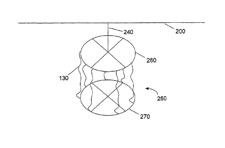
[0027] Figure 2C presents multiple collection fibers in a squirrel cage
arrangement with
top and bottom support members. Support structure 250 may be connected to
support
structure wire 200 by support member 240. Structure 250 has a top 260 and a
bottom 270
and each of the multiple collection fibers 130 are connected on one end to top
260 and on
the other end to bottom 270. A plurality of diodes may be placed at any
position on
support structure 250. A preferred embodiment places a diode at an elevated
position at
the connection point between collection fiber 130 and support structure wire
200.
[0028] Figure 2D presents another exemplary embodiment of a support
structure with
support members 275 in an x-shape connected to support structure wire 200 at
intersection 278 with collection fibers 130 connected between ends of support
members
275. A plurality of diodes may be placed at any position on the support
structure. A
preferred embodiment places a diode at an elevated position at the connection
point
between collection fiber 130 and support wire 200.
[0029] Figure 2E provides another exemplary embodiment for supporting
collection fiber
130. Collection fiber 130 may be connected on one side to support member 285,
vvhich
6
CA 02647385 2008-09-25
WO 2007/098341
PCT/US2007/062114
may be connected to support structure wire 200 in a first location and on the
other side to
support member 280, which may be connected to support structure wire 200 in a
second
location on support structure wire 200. The first and second locations may be
the same
location, or they may be different locations, even on different support wires.
A plurality
of diodes may be placed at any position on the support structure. A preferred
embodiment places one or more diodes at elevated positions at the connection
point(s)
between collection fiber 130 and support wire 200.
[0030] Figure 2F presents another exemplary embodiment of a support for
a collection
fiber. Two support members 290 may support either side of a collection fiber
and are
connected to support wire 200 in a single point. A plurality of diodes may be
placed at
any position on the support structure. A preferred embodiment places a diode
at an
elevated position at the connection point between collection fiber 130 and
support wire
200.
[0031] Figure 2G provides two supports as provided in Figure 2F such
that at least two
support members 292, 294 may be connected to support structure wire 200 in
multiple
locations and collection fibers 130 may be connected between each end of the
support
structures. Collection fibers 130 may be connected between each end of a
single support
structure and between multiple support structures. A plurality of diodes may
be placed at
any position on the support structure. A preferred embodiment places one or
more diodes
at elevated positions at the connection point(s) between collection fiber 130
and support
structure wire 200.
[0032] Figure 3 provides a schematic diagram of storing circuit 300 for
storing energy
collected by one or more collection devices (130 from Figure 2). Load 150
induces
current flow. Diode 310 may be electrically connected in series between one or
more
collection devices (130 from Figure 2) and load 150. A plurality of diodes may
be placed
at any position in the circuit. Switch 330 may be electrically connected
between load 150
and at least one collection device (130 from Figure 2) to connect and
disconnect the load.
Capacitor 320 may be connected in parallel to the switch 330 and load 150 to
store energy
when switch 330 is open for delivery to load 150 when switch 330 is closed.
Rectifier
340 may be electrically connected in parallel to load 150, between the
receiving end of
7
CA 02647385 2008-09-25
WO 2007/098341
PCT/US2007/062114
switch 330 and ground. Rectifier 340 may be a full-wave or a half-wave
rectifier.
Rectifier 340 may include a diode electrically connected in parallel to load
150, between
the receiving end of switch 330 and ground. The direction of the diode of
rectifier 340 is
optional.
[0033] In an exemplary embodiment provided in Figure 4, storage circuit
400 stores
energy from one or more collection devices (130 from Figure 2) by charging
capacitor
410. If charging capacitor 410 is not used, then the connection to ground
shown at
capacitor 410 is eliminated. A plurality of diodes may be placed at any
position in the
circuit. Diode 310 may be electrically connected in series between one or more
collection
devices (130 from Figure 2) and load 150. Diode 440 may be placed in series
with load
150. The voltage from capacitor 410 can be used to charge spark gap 420 when
it reaches
sufficient voltage. Spark gap 420 may comprise one or more spark gaps in
parallel. Non-
limiting examples of spark gap 420 include mercury-reed switches and mercury-
wetted
reed switches. When spark gap 420 arcs, energy will arc from one end of the
spark gap
420 to the receiving end of the spark gap 420. The output of spark gap 420 may
be
electrically connected in series to rectifier 450. Rectifier 450 may be a full-
wave or a half-
wave rectifier. Rectifier 450 may include a diode electrically connected in
parallel to
transformer 430 and load 150, between the receiving end of spark gap 420 and
ground.
The direction of the diode of rectifier 450 is optional. The output of
rectifier 450 is
connected to transformer 430 to drive load 150.
[0034] Figure 5 presents motor driver circuit 500. One or more
collection devices (130
from Figure 2) are electrically connected to static electricity motor 510,
which powers
generator 520 to drive load 150. A plurality of diodes may be placed at any
position in the
circuit. Motor 510 may also be directly connected to load 150 to drive it
directly.
[0035] Figure 6 demonstrates a circuit 600 for producing hydrogen. A
plurality of diodes
may be placed at any position in the circuit. One or more collection devices
(130 from
Figure 2) are electrically connected to primary spark gap 610, which may be
connected to
=
secondary spark gap 640. Non-limiting examples of spark gaps 610, 640 include
mercury-
reed switches and mercury-wetted reed switches. Secondary spark gap 640 may be
immersed in water 630 within container 620. When secondary spark gap 640
immersed
8
=
CA 02647385 2008-09-25
WO 2007/098341
PCT/US2007/062114
in water 630 is energized, spark gap 640 may produce bubbles of hydrogen and
oxygen,
which may be collected to be used as fuel.
[0036] Figure 7 presents circuit 700 for driving a fuel cell. A
plurality of diodes may be
placed at any position in the circuit. Collection devices (130 from Figure 2)
provide
energy to fuel cell 720 which drives load 150. Fuel cell 720 may produce
hydrogen and
oxygen.
[0037] Figure 8 presents exemplary circuit 800 for the collection of
energy. Storage
circuit 800 stores energy from one or more collection devices (130 from Figure
2) by
charging capacitor 810. If charging capacitor 810 is not used, then the
connection to
ground shown at capacitor 810 is eliminated. A plurality of diodes may be
placed at any
position in the circuit. The voltage from capacitor 810 can be used to charge
spark gap
820 when it reaches sufficient voltage. Spark gap 820 may comprise one or more
spark
gaps in parallel or in series. Non-limiting examples of spark gap 820 include
mercury-
reed switches and mercury-wetted reed switches. When spark gap 820 arcs,
energy will
arc from onè end of spark gap 820 to the receiving end of spark gap 820. The
output of
spark gap 820 may be electrically connected in series to rectifier 825.
Rectifier 825 may
be a full-wave or a half-wave rectifier. Rectifier 825 may include a diode
electrically
connected in parallel to inductor 830 and load 150, between the receiving end
of spark
gap 820 and ground. The direction of the diode of rectifier 825 is optional.
The output of
rectifier 825 is connected to inductor 830. Inductor 830 may be a fixed value
inductor or a
variable inductor. Capacitor 870 may be placed in parallel with load 150.
[0038] Figure 9 presents a flow diagram of a method for collecting
energy. In block 910,
one or more collection devices may be suspended from a support structure wire.
In block
920, a load may be electrically connected to the support structure wire to
draw current. In
block 930 a diode may be electrically connected between the support structure
wire and
the electrical connection to the load. In block 940, energy provided to the
load may be
stored or otherwise utilized.
[0039] Any process descriptions or blocks in flow charts should be
understood as
representing modules, segments, or portions of code which include one or more
executable instructions for implementing specific logical functions or steps
in the process,
9
CA 02647385 2008-09-25
WO 2007/098341
PCT/US2007/062114
and alternate implementations are included within the scope of the preferred
embodiment
of the present disclosure in which functions may be executed out of order from
that
shown or discussed, including substantially concurrently or in reverse order,
depending
on the functionality involved, as would be understood by those reasonably
skilled in the
art of the present disclosure.
[0040] It should be emphasized that the above-described embodiments of
the present
disclosure, particularly, any "preferred" embodiments, are merely possible
examples of
implementations, merely set forth for a clear understanding of the principles
of the
disclosure. Many variations and modifications may be made to the above-
described
embodiment(s) of the disclosure without departing substantially from the
spirit and
principles of the disclosure. All such modifications and variations are
intended to be
included herein within the scope of this disclosure and the present disclosure
and
protected by the following claims.