Note: Descriptions are shown in the official language in which they were submitted.
CA 02647389 2008-09-24
WO 2007/123739 PCT/US2007/007985
TOOTHED POWER TRANSMISSION BELT
BACKGROUND OF THE INVENTION
1. Field of the Invention
[0001] The present invention relates generally to toothed
belts and, more specifically, to a relatively thick jacket, thin
cord, toothed belt.
2. Description of the Related Art
[0002] It is known to provide a toothed belt for an
engine such as a synchronous belt that transmits load and motion
by the action of molded teeth in grooves in a pulley for the
engine. Typically, the toothed belt includes a belt body, a
jacket disposed along at least one toothed peripheral surface of
the belt body, and a.tensile member embedded in the belt body.
The belt body has a plurality of belt teeth formed of the body
and spaced apart at a predetermined pitch. The tensile member is
comprised of one or more cords embedded in the belt body.
[0003] It is also known that the toothed belt and pulley
have certain geometrical relationships. For example, as
illustrated in FIG. 1, a pulley 6 has an outside diameter (OD)
and a pitch diameter (PD) describing a circular pitch (CP) or
tooth repeat distance, relative to the center (C) of the pulley
B04-061PCTpd_final.doc
CA 02647389 2008-09-24
WO 2007/123739 PCT/US2007/007985
2
6. A belt 8 has a belt pitch line (BPL) or neutral axis also
describing a CP. The CP of the belt must match the CP of the
pulley for proper engagement or fit. The pulley 6 has a pitch
line differential (PLD) that is half the difference between the
PD of the pulley 6 and the OD of the pulley 6. The belt 8 has a
PLD that is equal to the distance between the BPL and a belt
land. The land is the bottom surface of the groove between
adjacent longitudinally spaced teeth of the belt and is indicated
by reference numeral 20 in FIG. 3. Typically, a center or
neutral axis of the tensile member lies, or is assumed to lie,
along the BPL of the belt.
[0004] It is further known that engine designers maintain
standard PLD and pitch line differentials in the design of the
engine. Exemplary standards include SAE J1278 and ISO 9010 for
automotive under-hood synchronous drives and RMA IP-24 and ISO
5296-1 for industrial synchronous drives. The PLD and pitch are
critical dimensions that insure a sufficient engagement between
the teeth of the belt and the cooperating pulley. As a result,
belts designed for existing engines conventionally have to
incorporate a standard PLD. It is general practice to design the
PLD of the belt to match that of the pulley system, so that BPL
and PD coincide as shown in FIG. 1, within practical tolerances.
The pitch of the belt is generally controlled by properly
selecting the mold dimensions. The PLD of the belt is generally
controlled by the dimensions and properties of the tensile member
and jacket. Nevertheless, some engine designers have designed
CA 02647389 2008-09-24
WO 2007/123739 PCT/US2007/007985
3
belt drive systems incorporating various pulleys that do not
match each other and/or that have non-standard PLD, thus placing
severe stresses on the belt.
[0005] Moreover, automotive designers are demanding that
overhead cam belt systems also drive additional components such
as water pumps, fuel pumps, and the like placing increasingly
severe loads on the belt. Previously, to boost the load carrying
capability of a synchronous belt, a physical property of the
elastomeric compound for the belt body was changed, generally
reducing belt flexibility. Alternately, or in addition, changes
in jacket and/or tensile member construction or use of newer,
high-performance fiber materials have been investigated.
However, a change in the dimensions of the tensile member or
jacket to allow more flexibility and/or load capacity in the belt
will result in a change in the PLD, with the potential of
adversely affecting pitch fit. Thus, although changes to the
tensile member or jacket could also favorably affect load
capacity, the aforementioned geometrical restrictions have placed
rather tight limitations on the practical extent of such changes.
[0006] The interaction between the belt body, the tensile
member, and the jacket is therefore important for the belt
geometry, operation in a given drive system, and life and
performance of the belt. Examples of such interaction and prior
attempts to manipulate cord and jacket variables to achieve
performance improvement have been disclosed. In U.S. Patent No.
4,721,496 to Yokoyama et al., a very narrow range of fiberglass
CA 02647389 2008-09-24
WO 2007/123739 PCT/US2007/007985
4
cord diameter, 0.9 to 1.1 millimeters (mm), combined with a cord
diameter to jacket thickness ratio in the range from 1.8 to 5.0,
was disclosed. In U.S. Patent No. 5,531,649 to Osako et al.,
belts with an above-nominal PLD of between 0.73 and 0.85 mm,
combined with a jacket thickness of between 0.3 and 0.5 mm, with
glass or aramid cord, were disclosed. In U.S. Patent No.
5,209,961 to Yokoi, belts with glass cord diameters of 0.63 mm to
0.85 mm, combined with a cord diameter to jacket thickness ratio
in the range from about 1.5 to 2.2, were disclosed. Thus,
changes in one of these components may not be facilitated unless
consideration is made for the other components. Yet, performance
of belts designed within these conventional parameter ranges have
failed to meet desired performance standards, and in some cases,
have failed to achieve even the minimum expected potential of
newer, high-performance materials such as carbon fiber. As such,
it is desired to focus on changes of the tensile member and
jacket, which complement one another to achieve a desired belt
geometry and improvement in performance.
[0007] Therefore, it is desirable to provide a new belt
construction for a synchronous belt that focuses on the tensile
member and jacket to achieve a desired belt geometry and
improvement in performance, including improved load capacity and
flexibility. It is also desired to provide a new belt
construction for a synchronous belt that uses smaller diameter
cords for the tensile member. It is further desirable to provide
a new belt design approach that results in improved performance
CA 02647389 2008-09-24
WO 2007/123739 PCT/US2007/007985
from high-strength, high-modulus cord materials. It is further
desirable to provide a new belt construction that functions
properly in a variety of pulleys within a predetermined pitch
line differential range. Therefore, there is a need in the art
to provide a toothed belt that meets at least one of these
desires.
SUMMARY OF THE INVENTION
[0008] Accordingly, one embodiment of the present
invention is a relatively thick jacket, thin cord, toothed belt
suitable for an automotive synchronous drive. The toothed belt
includes an elastomeric belt body, at least one tooth formed of
the belt body, a jacket disposed along a peripheral -surface of
the belt body, and a tensile member or cord embedded in the belt
body. The jacket has a compressed thickness of 0.5 mm to about
0.8 mm, and the ratio of the cord diameter to the jacket
thickness is less than 1.8, and the pitch line differential of
the belt is no more than about 1.2 mm.
[0009] An aspect of the invention is the selection of
cord fiber material from the group carbon, PBO, aramid, glass,
and a hybrid of two or more of the foregoing. The cord may be
carbon fiber and of cord diameter from about 0.5 mm to about 0.95
mm. The jacket may have a compressed gauge thickness of about
0.57 mm to about 0.75 mm.
[00010] In another embodiment, the invention is a
synchronous drive assembly comprising at least a driver and a
CA 02647389 2008-09-24
WO 2007/123739 PCT/US2007/007985
6
driven pulley having a predetermined design PLD, and a toothed
belt in driving engagement with said pulleys. The toothed belt
comprises an elastomeric belt body; a tensile cord having a
diameter; a jacket having a compressed thickness; and a belt
optical PLD. The ratio of the belt PLD to the design PLD is in
the range of from about 1.2 to about 1.75; and the ratio of the
cord diameter to the jacket thickness is in the range of from
about 0.7 to about 1.7. The cord may be carbon fiber of filament
count from about 1K to about 48K.
[00011] One advantage of the present invention is that a
thick jacket, thin cord, toothed belt is provided for a vehicle.
Another advantage of.the present invention is that the toothed
belt incorporates a new tensile member made from a 6K tow of
fiber for the cords thereof to increase a flexibility of the
belt. Yet another advantage of the present invention is that the
toothed belt has a thick jacket, which is a "stiff jacket", to
increase a tooth load carrying capacity of the belt. Still
another advantage of the present invention is that the toothed
belt has a thick jacket coupled to a small diameter cord that
improves the load carrying capability of the belt construction
together with other belt performance characteristics. A further
advantage of the present invention is that the toothed belt
functions properly in pulleys of a standard PLD or a range of
PLD. Yet a further advantage of the present invention is that
the toothed belt improves the potential service life of an engine
because a fabric for a thick jacket thereof will not wear out as
CA 02647389 2011-01-14
25145-520
7
quickly as a thin jacket. Still a further advantage of the present invention
is that
the toothed belt allows for the use of a small diameter "high flex", such as
6K
carbon fiber cord, for example when "thin cords" are required for "high flex"
drives.
Another advantage of the present invention is that the toothed belt has a
small
diameter highly flexible cord that reduces belt running temperature, thereby
reducing the onset of compound thermal degradation (i.e., compound aging). Yet
another advantage of the present invention is that the toothed belt has a 6K
yarn
that is not subject to tensile degradation as a function of hours or cycles on
motored engines, thereby increasing the life of the belt. Still another
advantage of
the present invention is that the toothed belt includes a tensile member
having a
cord with a physical geometry that is small in diameter and a jacket that is
great in
thickness when compared to current belt constructions.
[00011 a] According to one aspect of the present invention, there is
provided a toothed belt comprising: an elastomeric body; at least one tooth
formed of said body; a jacket disposed along a peripheral surface of said at
least
one tooth and having a compressed jacket thickness in the range from 0.5 mm to
about 0.8 mm; at least one cord embedded in said body and having a cord
diameter; said at least one cord and said jacket having a ratio of said cord
diameter to said jacket thickness of less than 1.8; and said cord diameter and
said
jacket thickness describing an optical belt Pitch Line Differential (PDL) of
about
1.2 mm or less, wherein said cord diameter is greater than 0.85 mm, or said
ratio
of said cord diameter to said jacket thickness is less than about 1.5, or
both.
[00011 b] According to another aspect of the present invention,
there is provided a synchronous drive assembly having a predetermined design
PLD and comprising at least a driver and a driven pulley, and a toothed belt
in
driving engagement with said pulleys; said toothed belt comprising: an
elastomeric belt body; a tensile cord having a diameter; a jacket having a
compressed thickness; and a belt optical PLD; wherein the ratio of the belt
PLD to
the design PLD is in the range of from about 1.2 to about 1.75; and the ratio
of the
cord diameter to the jacket thickness is in the range of from about 0.7 to
about 1.7.
CA 02647389 2011-01-14
25145-520
7a
[00012] Other features and advantages of the present invention will
be readily appreciated, as the same becomes better understood, after reading
the
subsequent description taken in conjunction with the accompanying drawings.
BRIEF DESCRIPTION OF THE DRAWINGS
[00013] FIG. 1 is a diagrammatic view of a pulley and a toothed belt
illustrating a geometrical relationship therebetween.
CA 02647389 2008-09-24
WO 2007/123739 PCT/US2007/007985
8
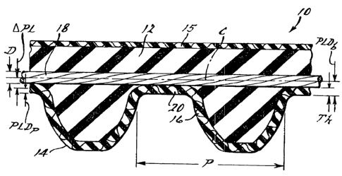
[00014] FIG. 2 is a perspective view of a thick jacket,
thin cord, toothed belt, according to the present invention.
[00015] FIG. 3 is a fragmentary view of the toothed belt
of FIG. 2.
[00016] FIG. 4 is a fragmentary view of a section of the
toothed belt of FIG. 2.
[00017] FIG. 5 is a diagrammatic view of a test
configuration utilized to characterize an aspect of the present
invention.
DETAILED DESCRIPTION OF THE INVENTION
[00018] Referring to the drawings and in particular FIGS.
2 and 3, one embodiment of a thick jacket, thin cord, toothed
belt 10, according to the present invention, is shown. The
toothed belt 10 includes a belt body 12 formed of any suitable
cured elastomer composition. The belt body 12 includes at least
one, preferably a plurality of belt teeth 14 formed of the belt
body 12 and spaced apart at a predetermined tooth pitch (P).
[00019] For utilization in the belt body elastomer
composition, any suitable and/or conventional elastomer type may
be employed, including both castable and non-castable elastomers
and also thermoplastic elastomers. As thermoplastic elastomers,
thermoplastic polyurethane ("TPU") may beneficially be employed.
As non-castable elastomers, chloroprene rubber ("CR"),
acrylonitrile butadiene rubber ("NBR"), hydrogenated NBR
("HNBR"), styrene-butadiene rubber ("SBR"), alkylated
CA 02647389 2008-09-24
WO 2007/123739 PCT/US2007/007985
9
chlorosulfonated polyethylene ("ACSM"), epichlorohydrin,
butadiene rubber ("BR"), natural rubber ("NR") and ethylene alpha
olefin elastomers such as ethylene propylene terpolymer ("EPDM")
and ethylene propylene copolymer ("EPM"), or a combination of any
two or more of the foregoing may beneficially be employed.
[00020] As castable elastomers suitable for use as the
belt body elastomer of the belts in accordance with the present
invention, urethanes, polyurethanes, urethane/ureas, and ureas
are mentioned as non-limiting examples. For castable elastomers,
the belt body 12 is cast of a liquid belt material that, when
cured, has,the requisite physical characteristics required of a
power transmission belt. For example, the material may have the
properties as disclosed in any of U.S. Pat. No. 4,838,843 to
Westhoff, U.S. Pat. No. 5,112,282 to Patterson et al., or in WOP
Publication No. 96/02584 (Feb. 1, 1996) to Wu et al.
[00021] Conventional elastomer composition additives
including fillers, short fibers, curatives, activators,
accelerators, scorch retarders, stabilizers, antioxidants,
antiozonants, and plasticizers may be utilized in conjunction
with the elastomer constituent itself to form the belt body
portions, in amounts conventionally employed for this purpose.
The belts of the present invention, which may be toothed as
illustrated in FIGS. 2 and 3, may be fabricated using known belt-
building techniques, any number of which would be readily
appreciated by one skilled in the relevant art. Examples of
power transmission belts, namely toothed or synchronous belts,
CA 02647389 2008-09-24
WO 2007/123739 PCT/US2007/007985
are disclosed in U.S. Pat. Nos. 2,507,852 and 3,138,962.
Examples of methods for producing such belts are disclosed in
U.S. Pat. Nos. 3,078,206, 3,772,929 and 4,066,732. It should be
appreciated that these patent references are merely examples of
various types of toothed power transmission belts and state-of-
the-art formation techniques thereof.
[00022] The belt teeth 14 formed of the belt body 12 may
have any desired cross-sectional shape such as trapezoidal,
curvilinear, or curvilinear truncated. Examples of curvilinear
tooth shapes appear in U.S. Pat. No. 3,756.,091 to Miller, U.S..
Pat. No. 4,515,577 to Cathey et al., and U.S. Pat. No. 4,605,389
to Westhoff. It should be appreciated that the belt teeth 14 are
spaced from each other by a predetermined pitch (P).
[00023] The toothed belt 10 also includes an optional
jacket 15 to cover the back of the belt body 12. The back of the
belt may optionally be without a jacket and/or ground smooth or
given a corrugated pattern. The belt may be a double sided
synchronous belt, with teeth on both sides, to which all
geometrical and material considerations with respect to the
single-sided belt would optionally apply doubly. The belt teeth
14 are covered with the jacket 16 as shown, disposed along
peripheral surfaces of the belt teeth 14. The jacket 16 is made
of a wear-resistant fabric for promoting tooth sheer strength
and, in castable belt constructions in particular, for reducing
aggressiveness of the belt teeth 14 when entering grooves of a
sprocket or pulley. The jacket 16 is relatively thick. The
CA 02647389 2008-09-24
WO 2007/123739 PCT/US2007/007985
11
jacket 16 has a compressed gauge thickness (Th). It should be
appreciated that the compressed jacket thickness is the thickness
of the jacket, after belt manufacture, when the jacket is part of
the belt structure, compressed in the belt.
[00024] Any suitable or conventional material may be
employed for the jacket 16, including crimped nylon, woven nylon,
cotton, hemp, jute, aramid, polyester, polytetrafluoroethylene
(PTFE), and fiberglass. The fabric may be woven, double-woven,
knit, or non-woven. More than one ply of fabric may be employed,
or more than one type of fabric may be combined in multiple
layers to achieve the desired total thickness. Examples of such
combinations are disclosed in U.S. Pat. No. 5,971,879 to
Westhoff. If desired, the fabric may be cut on a bias so that
the strands form an angle with the direction of travel of the
toothed belt 10. The fabric may be of any desired configuration
such as a conventional weave consisting of warp and weft threads
at any desired angle, or may consist of pick cords, or of a
knitted or braided configuration or the like. It should be
appreciated that a plurality of transversely oriented grooves
(not shown) may optionally be formed in an outer layer or back
side of the toothed belt 10. It should also be appreciated that,
while not necessary, the grooves reduce belt weight and may
enhance belt flexibility in some applications or under certain
circumstances, particularly wherein a castable material is used
to form the belt body 12. The jacket fabric may be treated with
a rubber composition compatible for bonding to the belt body.
CA 02647389 2008-09-24
WO 2007/123739 PCT/US2007/007985
12
The treatment may be a rubber solution or RFL dip, or calendered,
frictioned, or skimmed rubber, and the like. A layer of rubber
may be provided on one side of the fabric as a cushion layer
between fabric and cord. The fabric may have a thermoplastic
film laminated to one side as disclosed in U.S. Pat. No.
3,964,328.
[00025] In one embodiment particularly suited for
automotive applications with system design PLD of about 0.686 mm
or with actual pulley PLD ranging from about 0.6 mm to about 0.8
mm, the jacket thickness (Th) is in a range from about 0.5 mm to
about 0.8 mm, and the ratio of cord diameter to jacket thickness
is less than 1.8, and the belt PLD is no more than about 1.2 mm.
An exemplary jacket 16 comprises Nylon 6-6 texturized yarns
.woven.in a twill pattern with a fabric weight of between about
500 to about 700 grams per square meter (gsm), preferably a
weight of between about 550 gsm to about 650 gsm. In this
embodiment, the jacket 16 has a greige fabric original gauge
thickness of about 1.83 mm and a treated fabric/original jacket
gauge thickness of about 2.1 mm before being compressed to the
compressed gauge thickness (Th). Thus, when combined in this
embodiment with a suitable cord of diameter from about 0.5 to
about 0.9 mm, the ratio of the cord diameter (D) to the original
jacket gauge thickness may be in the range from about 0.24 to
about 0.43, and the ratio D/Th may be in the range from about 0.7
to about 1.8. Preferably the cord diameter may be in a range
CA 02647389 2008-09-24
WO 2007/123739 PCT/US2007/007985
13
from about 0.6 to about 0.85 mm. A suitable cord comprises 6K
carbon fiber and has a diameter of about 0.7 to about 0.8 mm.
[00026] The toothed belt 10 includes a tensile member 18
embedded in the belt body 12. The tensile member 18 includes at
least one, preferably a plurality of helically spiraled cords
embedded in the belt body 12. In this embodiment, the tensile
member 18 in the form of a cord is helically spiraled across the
width of the toothed belt 10 as a matched pair of S and Z twisted
cord in spaced side-by-side fashion according to common practice
in the art. The cord in non-limiting embodiments of the present
invention may thus occupy from about fifty-six percent (56%) to
about ninety-five percent (95%) of the belt width, and preferably
from about sixty-five percent (65%) to about ninety-two percent
(92%) of the belt width.
[00027] The cord of the tensile member 18 comprises a
plurality of twisted and/or bundled yarns at least one of which
comprises a yarn of fibers. In the present context and
throughout the present application, the terms "fiber" and
"filament" are utilized interchangeably to designate a material
having a small cross-sectional diameter, e.g., 4-9 m, and a
length at least about one hundred times its diameter, but
generally having an exceedingly great or even indefinite length,
and which forms the basic element of a yarn. The term "yarn" is
utilized herein and throughout the present application to
designate at least two, but generally with regard to fiber yarns,
one thousand or more fibers that are laid and/or twisted and/or
CA 02647389 2008-09-24
WO 2007/123739 PCT/US2007/007985
14
otherwise bundled together in a continuous strand to form a
component of a cord. The term "cord" is utilized throughout the
present application to designate the product of one or more yarns
that may be twisted as is known in the art, and where two or more
yarns are employed, may moreover be laid and/or bundled and/or
twisted together and/or treated with an adhesive treatment.
[00028] The fibers are high strength, high modulus fibers.
The fibers may be made, for example, of fiberglass, aramid,
poly(p-phenylene-2,6-benzobisoxazole) (PBO), carbon, or hybrid
combinations thereof. Preferably, the fibers are carbon fibers.
Exemplary carbon fibers for utilization in the practice of an
embodiment of the present invention are described for example in
aforementioned U.S. Pat. No. 5,807,194, the contents of which,
with regard to illustrative carbon fiber types, configurations,
and designations that may be utilized in the practice of
embodiments of the present invention, are incorporated herein by
reference. Carbon fiber is generally made by carbonizing an
organic fiber such as polyacrylonitrile (PAN), rayon, or pitch
fiber wherein in the carbonizing process the diameter of the
fiber is substantially reduced. Yarns formed from one or more
carbon fibers typically have a mass per unit length of from about
66 tex to about 1,650 tex, and a filament count (i.e., number of
individual carbon fibers per yarn) of from about 1,000 to about
54,000. The carbon fiber for use in accordance with the present
invention possesses a tensile modulus in the range of from about
50 GPa to about 600 GPa; preferably of from about 100 GPa to
CA 02647389 2008-09-24
WO 2007/123739 PCT/US2007/007985
about 300 GPa; and most preferably of from about 150 GPa to about
275 GPa, as determined in accordance with ASTM D4018. In
embodiments of the present invention wherein the cross-sectional
diameter of the individual carbon fibers is in the range of from
about 5 m to about 9 m, the filament count of the cord utilized
in the automotive power transmission application mentioned above
may be from about 3,000 to about 12,000, preferably about 6,000.
As is well known in the art, carbon yarn and cord formed
therefrom may be characterized by the number of fibers contained
therein rather than by denier or decitex. A nomenclature of
numbers and the letter "K" are used to denote the number of
carbon fibers in a yarn. Thus, in a "3K" carbon fiber yarn, the
"K" is an abbreviated designation for "1,000 fibers", and the "3"
designates a multiplier. Thus "3K" carbon yarn identifies a yarn
of 3,000 fibers or filaments. Moreover with regard to cord
nomenclature, in a "3K-2" carbon fiber cord for example, the "2"
indicates that two 3K yarns are twisted and/or otherwise bundled
together to thus form a cord having a filament count of 6,000.
[00029] The carbon fiber cord comprises any combination of
yarns suitable for a given application, including but not limited
to 1K-i, 3K-1, 3K-2,6K-1 ... 6K-9, 12K-1 ... 12K-4, 18K-i ... 18K-3,
24K-1, 24K-2, 48K-1, and the like, which provide a cord with a
diameter (D) determined by the design method to be discussed
below. Non-limiting examples of carbon fibers suitable for use
in practicing the present invention are made available
commercially by Toray Industries, Inc., under the references
CA 02647389 2008-09-24
WO 2007/123739 PCT/US2007/007985
16
TORAYCA-T400 HB 6K 40D and TORAYCA-T700 GC 6K; similar materials
are also available commercially through Toho Tenax Co., Ltd.,
under the references UT500-6k; and similar materials are further
available commercially through Cytec Industries, Inc., under the
references T-650/35 6K 309NT. Suitable glass fibers include E-
glass, or preferably high-strength glass such as S-glass, R-glass
or U-glass. Non-limiting examples of glass fibers suitable for
use in practicing the present invention are made available
commercially by AGY of Aiken, South Carolina, under the reference
762 S-2 Glass. Non-limiting examples of aramid fibers suitable
for use in practicing the present invention are made available
commercially by Dupont Chemical Company under the references
KevlarTM and NomexTM and by Teijin Techno Products Limited under
the references TechnoraTM, TwaronT", and TeijinconexTM. Non-
limiting examples of PBO fibers suitable for use in practicing
the present invention are made available commercially by Toyobo
Co., Ltd., under the reference ZylonT".
[00030] In addition, the cord may have a hybrid cord
construction. For example, the cord may have a carbon fiber (6K)
center core with fiberglass or aramid yarn wrapped around the
outside of the center core. In a hybrid cord construction
suitable for the aforementioned automotive application, the
center core has a diameter (D) of less than 0.8 mm. Preferably,
the core has a diameter (D) between about 0.55 mm and about 0.8
mm. It should be appreciated that the carbon fiber bundle is the
main load carrying component.
CA 02647389 2008-09-24
WO 2007/123739 PCT/US2007/007985
17
[00031] Fiber manufacturers typically coat fibers with a
sizing, which generally serves to inhibit fracturing as the fiber
is processed into yarns and wound onto spools, and/or to
facilitate wetting of the fibers and yarns formed therefrom with
cord treatment(s). In some instances, the sizing may thus have a
chemical structure that is compatible with a cord treatment
applied to the yarns and/or filaments for incorporation of
treated cord into a power transmission belt, and may for example
thus be a water- or solvent-based epoxy solution. Throughout the
present application, the term, "sizing" is used to denote a
generally thin film applied to a yarn and/or yarn filament at a
level of from about 0.2 to 2.0% dry weight, i.e., based on the
weight of the dried, so treated yarn or filament, i.e., the dried
yarn or filament to which the sizing had been applied, in order
to function as hereinabove described.
[00032] In accordance with an embodiment of the present
invention, an RFL composition, i.e., an elastomer latex
composition further comprising a resorcinol-formaldehyde reaction
product, may be applied as a cord treatment to at least a portion
of the yarn and/or one or more of its carbon filaments.
Throughout the present application, the term, "cord treatment" is
used to denote a material applied to a yarn and/or yarn filament
(which may or may not include a sizing) and located at least on a
portion of the yarn- and/or yarn filament surface and within at
least a portion of one or more interstices formed between such
filaments and yarn(s) of a cord formed through the bundling
CA 02647389 2008-09-24
WO 2007/123739 PCT/US2007/007985
18
and/or twisting and/or other combination or configuration of such
cord-treated yarn; and being applied to such yarn and/or yarn
filament at a level greater than two percent (2.0%) based on the
final weight of the so treated cord.
[00033] As the RFL constituents, any suitable materials
may be employed. The resorcinol-formaldehyde resin fraction in
the RFL solution preferably represents from about 2 to about 40%
by weight dry basis, with the latex fraction representing from
about sixty percent (60%) to about ninety-eight percent (98%)_
Preferably, the resorcinol-formaldehyde resin fraction represents
from about five percent (5%) to about thirty percent (30%) by
weight dry basis, and the latex fraction represents from seventy
percent (70%) to about ninety-five percent (95%). This
proportion in an embodiment of the present invention has been
found to allow for the various filaments of the carbon fiber to
be impregnated sufficiently to reduce abrasion and breaking
thereof, while maintaining sufficient flexibility necessary to
accomplish the twisting and cabling operations conventionally
employed. Irrespective of the particular fractions of
resorcinol-formaldehyde resin and latex employed or the pick-up
level achieved however, it has been found in the practice of the
present invention that the solids level of the cord treatment
solution should be brought to and maintained at a point wherein
the RFL solution remains substantially stable during the
treatment process.
CA 02647389 2008-09-24
WO 2007/123739 PCT/US2007/007985
19
[00034] The latex component in the RFL solution may be of
any suitable type, including HNBR, NBR, carboxylated HNBR,
carboxylated NBR, vinyl pyridine/styrene butadiene rubber
("VP/SBR"), carboxylated VP/SBR, SBR, hydrogenated SBR,
chlorosulfonated polyethylene ("CSM"), ethylene alpha-olefin-type
elastomer such as EPDM and EPM, or a combination of any two or
more of the foregoing. In a preferred embodiment, the latex
component is a carboxylated HNBR type, and may include minor to
up to equal amounts or proportions by weight or more of other
elastomer types, including ethylene alpha-olefin-type elastomers
such as EPDM or EPM. Ethylene alpha olefin elastomer may be
utilized singly or in combination of any two or more. thereof to
improve low temperature performance properties of the resultant
belt, such as low temperature flexibility.
[00035] Other cord treatments known in the art may also
suitably be used, such as the epoxy-latex/RFL two-step treatment
disclosed in U.S. Pat. No. 6,500,531 for carbon fiber cord, or
the similar treatment for PBO cord disclosed in U.S. Pat. No.
6,824,871, or the solvent-based epoxy-rubber/RFL treatment for
carbon fiber disclosed in U.S. Pat. No. 4,883,712.
[00036] In embodiments of the present invention, the cord
may have a diameter (D) of from about 0.2 mm to more than 2.1 mm.
The following discussion addresses an embodiment belt designed
to fit a standard automotive application with system design PLD
of 0.686 mm (0.027 inch) . For such a belt, D may range from
about 0.5 mm to about 0.9 mm. Preferably, the cord has a
CA 02647389 2008-09-24
WO 2007/123739 PCT/US2007/007985
diameter between about 0.7 mm and about 0.8 mm. A suitable cord
may comprise 6K carbon fiber. The center (C) of the cord defines
a neutral belt axis/pitch line as illustrated in FIG 2. The
standard design tolerance for pulley PLD is +0.05 -0.00 mm.
However, in at least one known automotive example, the pulley 6
(FIG. 1) has a pitch line differential (PLD) in the wider range
of about 0.648 mm (0.0255 inches) to about 0.775 mm (0.0305
inches) which causes pitch fit problems for conventional belts_
The neutral belt axis of the inventive belt is located above the
greatest pulley PLD. The belt has a differential pitch line
(APL) that is the difference between the PLD or neutral axis of
the belt and the design pulley PLD of 0.686 in this case. The
LPL is in a range of about 0.09 mm (0.003 inches) to about 0.5 mm
(0.02 inches). Preferably, APL is in a range of about 0.16 mm to
about 0.51 mm, or from about 0.16 mm to about 0.36 mm. It should
be appreciated that the APL is also the difference in pitch line
between the toothed belt 10 and the pulley 6. The tensile member
18 and jacket 16 described above thus together provide a belt
that may have a PLD in the range of from about 0.78 mm to about
1.2 mm, or preferably in the range from 0.85 mm to about 1.2 mm
or in the range from about 0.85 to about 1.1 mm. The tensile
member 18 and jacket 16 described above together provide a belt
that may have a D/Th in the range of from about 0.7 to about 1.8,
or preferably from about 0.9 to about 1.6, or from about 1.0 to
about 1.5.
CA 02647389 2008-09-24
WO 2007/123739 PCT/US2007/007985
21
[00037] As illustrated in FIG. 4, the PLD of the toothed
belt 10 can be measured optically and calculated based on the
jacket surface position (PFS) , the cord-fabric interface (PcF),
and the body rubber-cord interface (PRC), all determined at a
cross section of the belt through a land area (20 in FIG. 3).
The average jacket thickness (Th) is equal to the absolute value
of the difference between the average PCF and. the average PFS .
The average cord diameter (D) is equal to the absolute value of
the difference between the average PRC and the average PCF. The
optical PLD is equal to the average jacket thickness (Th) plus
half of the average cord diameter (D), i.e. PLD.= Th + D/2. It
should be appreciated that the optical PLD of the toothed belt 10
is measured based on an average of several readings, preferably
taken at one or more land 20 positions around the belt.
[000381 To design a belt suitable for a given drive
system, there are five variables that must be taken into
consideration. The five variables are D (diameter of the cord),
Th (thickness of the jacket), PLDp (pitch line differential of
the pulley or drive system), PLDb (pitch line differential of the
belt which is based on the optical dimensional measurement
previously described), and APL (the difference in pitch line
between the belt and the pulley). Alternately, PLr (pitch line
or PLD ratio) may be used as the fifth design variable instead of
APL. The PLDp is generally given by design and is considered the
design PLD of a conventional belt/drive system. Two equations
are provided: (1) APL = PLDb-PLDp or PLr = PLDb/PLDp, and (2)
CA 02647389 2008-09-24
WO 2007/123739 PCT/US2007/007985
22
PLDb = Th + D/2. Thus, to specify the belt, two more equations
or variables must be supplied by the designer. Two design
approaches are practical. (1) If the variable D/Th is in a given
range, and either LPL or PLr is also in a given range, the design
method is called a "thickness ratio" approach. This design method
may be considered independent of the PLDp, or applicable to any
desired PLDp. (2) If D and Th are given or in given ranges, then
PLDb is easily calculated, and LPL or PLr become dependent on the
PLDp and easily calculated, and the design method is called an
"actual thickness" approach. Specifying D and Th generally
yields a belt suitable only for a specific PLDp. It should be
appreciated that the toothed belt 10 may be designed based on
these variables and by either method.
[00039] Thus, according to the actual thickness approach,
by way of a design example, a preferred jacket thickness of from
0.5 to 0.7 mm and a preferred cord diameter of from 0.6 to 0.8 mm
may be specified. As a result, the ratio D/Th will range from
about 0.9 to about 1.6. Also as a result, the PLDb will range
from about 0.8 to about 1.1 mm. It may be generally preferable
to narrow the specified ranges somewhat to maintain a ratio of
D/Th in the range from about 1 to about 1.5 and a PLDb in the
range from 0.85 to 1.08 mm. Then, as a result, for a design PLDp
of 0.686 mm, the LPL of the belt/pulley system will be in a
preferred range of from about 0.16 to about 0.36 mm. This design
example may be applicable to a belt for an automotive overhead
cam drive system.
CA 02647389 2008-09-24
WO 2007/123739 PCT/US2007/007985
23
[00040) Alternatively, according to the thickness ratio
design approach, by way of example, the ratio PLr may be
specified to be in the range from about 1.2 to about 1.75, or
from 1.24 to about 1.75, or preferably from about 1.24 to about
1.6. The ratio D/Th may be in the range from about 0.7 to about
1.8, or in a preferred range of from about 0.9 to about 1.6, or
from about 1.0 to about 1.5. As a result, for a specified PLDp
of, for example, 0.686 mm, the PLDb must then be in the range
from about 0.83 to about 1.20 mm, or preferably from about 0.85
to about 1.2, or from about 0.85 to about 1.1. Given PLr and
PLDp and D/Th, the cord diameter and jacket thickness can then be
properly selected to provide PLDb.. Thus, thick jacket, thin cord
belts according to the present invention can be designed for any
desired belt/pulley system PLD. This thickness ratio approach,
applied by way of example to the standard industrial synchronous
pulley sizes or "sections" listed in the standard RMA IR-24,
yields the ranges for cord diameter and jacket thickness listed
in Table 1. Each combination listed is a proportionately scaled
embodiment of the inventive thick jacket, thin cord, toothed belt
using the narrowest ranges listed above for PLr and D/Th. It
should be appreciated that the industrial H section belt is
equivalent in PLD to the most common automotive PLD, 0.686 mm.
By way of example, a carbon fiber cord construction approximating
a nominal diameter in the desired range is listed for each belt
section in Table 1. It should be understood that suitable cords
of each desired diameter range may be constructed from aramid,
CA 02647389 2008-09-24
WO 2007/123739 PCT/US2007/007985
24
glass, PBO or other suitable high strength, high modulus fibers.
It should also be understood that the same design approach can
be applied to metric belt sizes such as 2-mm, 3-mm, 5-mm, 8-mm
and 14-mm pitches and the like, and for any desired tooth
profile.
Table 1.
Belt PLDb-range Carbon Nominal D-range Th-range
Section PLDp (mm) (mm) Fiber D (mm) (mm) (mm)
Cord
MXL, XL 0.254 0.32-0.41 1k 0.29 0.21-0.35 0.18-0.27
L 0.381 0.47-0.61 3k 0.5 0.31-0.52 0.27-0.41
H 0.686 0.85-1.1 6k or 0.75 or 0.57-0.95 0.49-0.73
12k 0.95
XH 1.397 1.73-2.24 18k or 1.24 or 1.15-1.92 1.0-1.5
24k 1.45
XXH 1.524 1.89-2.44 24k 1.45 1.26-2.1 1.1-1.6
[000411 The toothed belt 10 fits the pulley PLD of
existing engines but is significantly altered from conventional
belt design by decreasing the diameter of the tensile member 18
and more than proportionately increasing the thickness of the
jacket 16. The smaller diameter tensile member 18 takes less
energy to bend, which reduces the generation of heat, in turn,
reducing the running temperature of the toothed belt 10, thereby
reducing the aging of the compound for the body 12. The use of
high-strength, high-modulus fibers such as carbon fibers for the
tensile member 18 maintains tensile strength of the toothed belt
10. The thick jacket 16 boosts the load capacity of the belt
teeth 14 while using standard elastomer compounds. As a result,
CA 02647389 2008-09-24
WO 2007/123739 PCT/US2007/007985
the toothed belt 10 lasts longer with abrasion because it takes
longer to wear through the thicker jacket 16. It should be
appreciated that a larger diameter tensile member takes more
energy to bend, resulting in the generation of heat and quicker
aging of the body compound.
[00042] The toothed belt 10 has a cord to fabric ratio
that maintains the desired 1PL or PLr rather than the
conventional approach of matching the pulley PLD within
relatively tight tolerances. For example, an inventive toothed
belt having a tensile member of 6K carbon fiber yarn and a
relatively thick jacket is compared to conventional toothed belts
having tensile members of glass fiber yarn and of 12k carbon
fiber as illustrated in Table 2 as follows:
Table 2.
Jacket Compressed
Construction Cord gauge Ratio gauge Ratio PLDb
D (mm) (mm) Th (mm) D/Th (mm)
Comparative 1.0 1.6 0.63 0.2-0.3 4 0.75
Std. Glass
Comparative 0.95 1.6 0.59 0.2-0.3 4 0.73
Carbon 12K
Inventive 0.75 2.1 0.36 0.5-0.7 1.25 0.98
Carbon 6K
This comparison indicates that the inventive toothed belt 10
having a tensile member of 6K carbon fiber yarns has a lower
ratio of cord diameter to jacket thickness and a higher belt
PLD than conventional belts. Thus, the toothed belt 10 having
a tensile member of 6K carbon fiber yarns has lower initial
CA 02647389 2008-09-24
WO 2007/123739 PCT/US2007/007985
26
tensile strength but a high flex cord that reduces belt
running temperature.
[00043] To illustrate the effects of the present
invention, toothed belts were formed using tensile members formed
of standard glass yarns, 12K carbon fiber yarns, and 6K carbon
fiber yarns. The belts differed only in jacket thickness and
cord material. Each of the belts had a 25 mm top width and 141
teeth (9.525 mm pitch) and measured about 1343.025 mm in length.
The teeth were curvilinear. To maintain the standard automotive
tooth pitch and fit pulleys with a 9.525 mm pitch at nominal belt
length, the mold for the inventive belt only was cut to have a
PLD of 0.94 mm. In each of the following examples set forth in
Table 3, each belt had an original belt tensile strength and were
tested for a number of hours to a final belt tensile strength:
Table 3.
Belt Belt Tensile Test time(s) Belt Tensile
Strength Strength
(Identification) Original (Hrs) Final
(kN/20mm) (kN/20mm)
Comparative 37 330 ave All Tensile
Std Glass failure
Comparative 34 792 803 Complete belt
12K Carbon / failure
Inventive 1362 / 1574 / 21.9 / 21.5 /
6K Carbon 25 1936 21.2
[00044] The three different cord material belts as
described above for each of the examples set forth in Table 3
were built using cord-jacket combinations as set forth in Table 2
and tested on a test rig 30 as illustrated in FIG. S. The test
CA 02647389 2008-09-24
WO 2007/123739 PCT/US2007/007985
27
rig 30 was built to simulate the timing belts used on a 1900cc,
four-cylinder, direct-injection, diesel engine. The test rig 30
includes seven pulleys 32, 34, 36, 38, 40, 42, and 44 as shown in
the schematic depiction provided in FIG. 4. The pulley 32
represented a driver or crankshaft pulley, the pulley 34
represented a tensioner pulley, the pulley 36 represented a
camshaft pulley, the pulley 38 represented an idler pulley, the
pulley 40 represented a fuel injector pump pulley, the pulley 42
represented a water pump pulley, and the pulley 44 represented an
idler pulley. The pulley 32, pulley 36, pulley 40, and pulley 42
each possessed sprocket grooves (22, 44, 44, and 19 in number,
respectively) for meshing with the belt teeth, at a 9.525 mm
pitch, but with different PLDp (0.648 mm, 0.749 mm, 0.749 mm, and
0.775 mm, respectively). The pulleys 38 and 44 were plain, i.e.,
non-toothed pulleys, measuring 28 mm and 80 mm in diameter,
respectively, and auto-tensioner pulley 34 was plain and measured
67 mm in diameter. A test apparatus included a chamber
containing the test rig 30 and within which the temperature was
held at 120 C throughout the test.
[00045] The belts were operated on the test rig 30 in a
clockwise direction under a "4-mm" load, which represents maximum
load or displacement of the fuel injector pump, at 4000 RPM
applied by electric motor at the'crankshaft or driver pulley 32,
with an installation tension of 500 N imposed by the automatic
mechanical tensioner 34, and with a peak tight side tension
caused by the fuel injector pump of 2,500 N, as measured by
CA 02647389 2008-09-24
WO 2007/123739 PCT/US2007/007985
28
strain gauges in pulley 34. The belt was tested until either
failure or a final belt tensile was achieved. These results
indicate that three comparative toothed belts having a tensile
member formed of standard glass fiber yarn all had tensile
failures at approximately 330 hours, and two comparative toothed
belts having a tensile member formed of 12K carbon fiber yarn had
a complete belt failure at 792 and 803 hours, respectively. On
the other hand, three inventive toothed belts having a tensile
member formed of 6K carbon fiber yarn were tested for 1362, 1574,
and 1936 hours, respectively, and had a final belt tensile of
21.9, 21.5, and 21.2 kN/20 mm, respectively. The inventive belts
exhibited signs of normal wear failure, including jacket wear in
the land areas and on tooth flanks. Therefore, the toothed belt
having a relatively thick jacket and thin cord of 6K carbon
had a lower initial tensile strength, but a much longer life, and
a more desirable mode of failure.
[00046] Accordingly, the toothed belt 10 of the present
invention has a small diameter cord with a thick fabric/jacket to
maintain a belt PLD much greater than the pulley PLD. The
toothed belt 10 has lower initial tensile strength and a high
flex cord that reduces belt running temperature. The toothed
belt 10 has a high gauge fabric that improves tooth-loading
capability and tooth and land wear resistance.
[00047] The present invention has been described in an
illustrative manner. It is to be understood that the
terminology, which has been used, is intended to be in the nature
CA 02647389 2008-09-24
WO 2007/123739 PCT/US2007/007985
29
of words of description rather than of limitation. Many
modifications and variations of the present invention are
possible in light of the above teachings. Therefore, within the
scope of the appended claims, the present invention may be
practiced other than as specifically described. The invention
disclosed herein may suitably be practiced in the absence of any
element that is not specifically disclosed herein.