Note: Descriptions are shown in the official language in which they were submitted.
CA 02647477 2008-09-25
25213-99
APPARATUS FOR THERMALLY DEHALOGENATING
HALOGENATED SUB STANCES
[DEVICE FOR THE THERMAL DEHALOGENATION
OF HALOGEN-CONTAINING SUBSTANCES]
100011 The present invention relates to a device for the dehalogenation, in
particular
debromination of halogen-containing, respectively bromine-containing
substances, in
particular of waste materials, as set forth in the first claim. The device is
used, in
particular, for the debromination of fluid substances, in particular of
carbonaceous
substances, such as oils, as well as for the liquefaction of polypropylene in
the course of a
thermal treatment in a reactor.
100021 Its commercial application potential resides, in particular, in the
disposal of
brominated starting material, for example when converting mother liquors of
prepared
plastic fractions, in conjunction with a pyrolysis of electronic scrap, in the
treatment of
brominated oils, in the production of secondary fuels, as well as in the
chemical recycling
of polypropylene.
100031 In the case of solid starting material, the liquefaction thereof to
produce the
aforementioned fluid substances, for example by pyrolysis, constitutes the
preliminary
stage. Suitable starting materials generally include all organic materials or
components
which contain organic materials that are contaminated with halogens, in
particular
bromine, or that contain halogens or bromine.
[0004] The German Patent Application DE 102 34 837 Al describes a process
concept
for treating halogen-containing, in particular bromine-containing waste
materials by
pyrolysis, where recyclable materials and/or energy are able to be recovered,
and, in fact
without producing any further halogenated contaminants. In this context, the
waste
materials are mixed in a first step in an inert gas with a molten polyolefin
(substituted or
1
CA 02647477 2008-09-25
25213-99
unsubstituted). In a second step, the hydrogen halides formed during melting
are separated
off, the carbon-bromine bond splitting at temperatures above 270 C without the
use of a
coreactant. The phenyl radicals are stabilized, for example, by radical
recombination with
another aromatic compound. However, this reaction path leads to the formation
of
biphenyl derivatives, to carbonization and, undesirably, to the formation of
halogenated
dibenzo-p-dioxins (PBDD) and dibenzo-p-furans (PBDF). The latter are able to
be
effectively suppressed in a pyrolysis process in the presence of polyolefins,
such as
polyethylene or polypropylene. The actual debromination is then effected by
the attack of
the phenyl- and bromine radicals on the macromolecules of the polyolefin under
hydrogen
abstraction. If one starts out from bromophenol and polypropylene, for
example, then
phenol and hydrogen bromide are obtained as main products. Alkyl phenols and
alkyl
bromides are formed as secondary products. Adding polyethylene or
polypropylene allows
stable molecules to be formed from the radicals, thereby also preventing PBDD
and PBDF
from forming.
100051 The described method ensures, in particular, that organic substances,
such as
oils, are able to be debrominated, making them suited for further use as
secondary fuel.
[0006J However, successfully implementing the aforementioned process concept
necessitates a sufficient residence time to carry out the aforementioned,
required chemical
processes. An industrial-scale implementation under general commercial
conditions fails
precisely because of this point, since a residence time of the brominated
organic vapors in
the reactor (or waste stream through the reactor) that is comparatively short
relative to the
total treatment duration connotes only an incomplete conversion [reaetion]
(dehalogenation or debromination). On the other hand, simply prolonging the
residence
time increases the process time in an installation and thus limits throughput
and,
consequently, profitability without creating additional capacity.
[0007] Against this background, an object of the present invention to devise a
device
for debrominating oils and for liquefying polypropylene that will enable
organic substrates
2
CA 02647477 2008-09-25
25213-99
substances to be debrominated on an industrial scale and that will not exhibit
the
aforementioned limitations. It is intended, in particular, that the chemical
reaction referred
to in the context of the related art be able to be implemented within a
treatment time that is
considered suitable from a technical standpoint.
[0008] To achieve the objective, a device having the features set forth in the
first
claim is provided. The dependent claims having an antecedent basis in this
claim recite
advantageous refinements of the present invention.
[0009] The objective is achieved by a reactor having a reaction volume for
thermally
treating the halogenated substances, which, in addition to an inlet for the
mentioned
substances, has an inlet for the polyolefins. The reactor has a tempering
device to adjust
the temperatures required for a pyrolysis in the reaction volume to preferably
between
approximately 200 C and 500 C. The reaction volume includes a top vapor space,
as well
as a bottom sump (sump region).
100101 One important feature of the present invention relates to the location
and
design of the inlet for [introducing] the polyolefins into the reaction
volume. It has a
heating device for heating the polyolefin to above the softening point in
order to condition
the same prior to injecting it into the reaction volume, it being possible for
the heating
device to be constituted of the aforementioned tempering device. In the
aforementioned
temperature range, in particular, however, between approximately 300 and 400
C,
polyolefin, such as polypropylene (softening point around 200 C, decomposition
starting
at or above approximately 350 C) or polyethylene is in the softened conveyable
and
injectable state, i.e., within a viscosity range of between 10 and 70 Pas. The
polyolefin is
preferably input as a raw material, such as granular material, into a
conveyor, such as a
spiral conveyor or a melt pump, for example, and heated already therein, i.e.,
outside of
the reaction volume, until a pumpable mass is obtained.
100111 The device preferably includes an activable/deactivable recycling
option for
the polyolefin (return flow and re-feeding), i.e., a fluid connection for the
aforementioned
polyolefin melt between the inlet and the outlet for the polyolefin in the
reaction volume.
3
CA 02647477 2008-09-25
Depending on the specific embodiment, the fluid connection has a feed pump
and/or a
heating device.
[0012] The inlet includes at least one nozzle (including extruder assemblies),
which is
oriented in the reaction volume toward the substances to be dehalogenated. In
principle,
the nozzles allow the polyolefins to be injected into the substances over a
preferred large
specific surface area, thereby advantageously accelerating the chemical
processes taking
place. A multiplicity of parallel-connected nozzles distributed within the
reaction volume
allow the polyolefin to be distributed over the entire volume of the substance
to be
dehalogenated, thereby advantageously significantly reducing the time required
for a
complete reaction over the entire volume of the substance. In principle, the
chemical
kinetics inherent in the reactions described in the teaching of the
aforementioned German
Patent Application DE 102 34 837 Al may be selectively controlled as a
function of the
positioning and orientation of the nozzles in the reaction volume.
100131 The inlet for the polyolefin preferably discharges into the top vapor
space
which contains the substances to be dehalogenated in a molecular, thoroughly
miscible
form that is able to contacted by the polyolefin. This ensures that the
substances to be
dehalogenated have chemical access to the polyolefin as a coreactant, ideally
spontaneously and by all molecules. The substances are typically present as
gases, vapors,
liquids, or as dust or fine particles in the vapor space that is directly or
indirectly tempered
by the heating of the reaction volume. They may also form constituents of
molten or liquid
aerosols, atomizations or, in principle, also of suspensions.
100141 To implement the aforementioned thermal treatment in the reaction
volume, it
is necessary to establish and maintain an inert gas atmosphere, such as a
nitrogen
atmosphere, for example, which is introduced via a gas supply inlet. The gas
supply inlet
may be realized either as a separate, supplementary feed pipe or as a gas
supply inlet for a
two-substance or multi-substance nozzle for introducing the polyolefin or
components of
the halogenated substance, the inert gas assuming the function of a carrier
gas, for example
for an atomization.
100151 One specific embodiment relates to a reaction system featuring a top
feeding
of a polyolefin melt, i.e., having a nozzle assembly at the top in the
reaction volume and
4
CA 02647477 2008-09-25
oriented downward therefrom into the vapor space. The polyolefin is deposited
from above
onto the substances to be dehalogenated (by heating, preferably in gaseous or
vaporous
form) and mixed in, a large specific polyolefin surface area being ensured by
one nozzle,
preferably, however, by a multiplicity of individual nozzles of the nozzle
assembly. The
polyolefin is discharged from the nozzles either as fine threads or as
atomized molten
aerosol. In the latter case, tempering must be employed to substantially lower
the viscosity
of the polyolefin to the point where atomization is rendered possible without
a significant
pressure build-up in the conveying system. In the polypropylene (PP) example,
a
temperature range within the thermal decomposition range of PP (approximately
350 C),
of between approximately 300 and 400 C, preferably of between 330 and/or 360
C, is
targeted.
[0016] The problem of reaction kinetics encountered in a dehalogenation
process, i.e.,
the relatively slowly occurring reaction, is generally considered to be a
limiting factor. A
proposed countermeasure provides for inverting the application of the reaction
phases, as
mentioned above. In this context, the preferred polypropylene (PP) is present
as a flow-
through phase, while the halogenated substances, such as brominated oils, for
example, are
fed as liquid to be vaporized into the reaction volume. In a state
characterized by a large
specific surface area, the PP penetrates the circumambient substances to be
halogenated. A
greatest possible polypropylene melt surface area is realized (PP [molten]
threads or
droplets or mist) by feeding the polypropylene via one or a plurality of
nozzles, atomizers
or spinning heads, preferably in the top region of the reactor, which [melt
surface area] is
able to react with the halogenated or brominated substances contained in the
top vapor
space in the reaction volume. In addition, the polymer melt entering into the
sump region
of the aforementioned substances located below the vapor space is able to
entrain a portion
of the substances, such as oil, and then still cause the same to react in the
melt phase
(preferably in the sump region, but also in a PP recycling circuit). Moreover,
PP melt may
be drawn from the sump region and fed via a preferably heated connecting line
and an inlet
into the vapor space again, the entrained substances being recycled again into
the vapor
space and fed again to the dehalogenation process taking place there. The
substances
advantageously first exit the functioning device when they are dehalogenated.
Also,
pyrolysis products of the polyolefin passing over into the gas space enter
into reaction with
the halogenated or brominated products contained in the vapor space. To this
end, the
reactor is designed to be pressure-resistant, thereby allowing potential
reaction times to be
CA 02647477 2008-09-25
prolonged and hindering the tendency of products to pass into the gas phase
(Le Chatelier
principle).
[0017] The present invention is explained in greater detail in the context of
exemplary
embodiments and with reference to the following figures, which show:
[0018] FIG. 1: a cross section of a specific embodiment having a reaction
volume and inlets for polyolefin;
[0019] FIG. 2a and b: alternative design options for the inlets for
polyolefin;
100201 FIG. 3: a schematic view of another specific embodiment having a
spiral conveyor for polypropylene; as well as
100211 FIG. 4: the characteristic time curves for concentrations of various
bromine compounds in the case of a debromination.
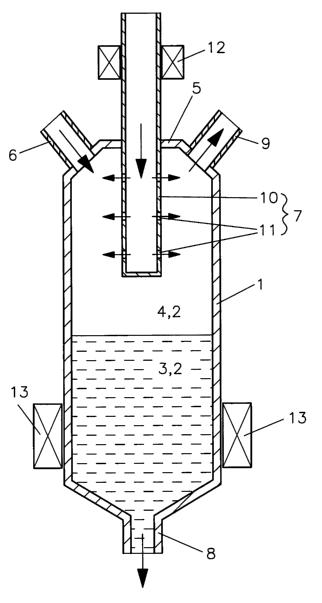
[0022] The specific embodiment shown in FIG. 1 includes a reactor 1 having a
reaction volume 2 where the substances to be dehalogenated are located in a
bottom sump
region 3 underneath a vapor space 4 in top region 5. The reactor also has a
substance
inlet 6, a polyolefin inlet 7, outlets for polyolefin 8, as well as for the
dehalogenated
substances and gas products 9. The last-mentioned outlets for the
dehalogenated
substances and the gas products may be jointly or separately configured, in
the case of a
jointly configured outlet, the dehalogenated substances and the gas products
(including
halogen compounds) being separated in a downstream stage (not shown). The
polyolefin
feed pipe includes a nozzle tube 10 that is closed on one side and that
features a
multiplicity of radially outwardly oriented individual nozzles 11 on the
peripheral surface.
The polyolefin to be injected is pressed into the nozzle tube, already
preheated by a
continuous-flow heater 12 and issues as fine jets or mist through individual
nozzles 11 into
vapor space 4. The reactor has a tempering device 13 to heat reaction volume
2.
Downpipe 8 may be designed as an extruder having a cutting-off device for a
solidifying
substance mixture containing the dehalogenated substances and polyolefin.
100231 An agitator (not shown) or some other circulation device may be
optionally
6
CA 02647477 2008-09-25
25213-99
provided in reaction volume 1 to further enhance the intermixing and thus
accelerate the
reaction.
100241 The aforementioned agitator may also be designed and utilized as a
polyolefin
feed pipe, by locating the same preferably on the stirring spoons, the
position thereof
constantly changing and advantageously accelerating an intermixing of the
polyolefin with
the substance mixture.
[0025] For an atomizer nozzle, FIG. 2a depicts exemplarily an alternative
polyolefin
inlet 7 in a sheath flow line 14 for an inert gas as a two-substance nozzle 15
for producing
a polyolefin mist or an aerosol. On the other hand, for a multi-nozzle
configuration for
producing fine threads or droplets, FIG. 2b illustrates exemplarily a
polyolefin feed pipe 7,
which discharges into a multiplicity of individual nozzles 11 which spread
apart in a three-
dimensional fan-shaped configuration.
100261 FIG. 3 shows another specific embodiment in a schematic system
representation. Polyolefin inlet 7 is designed as a horizontal pipe that is
closed on one side
having a horizontal nozzle array of substantially identical individual nozzles
(bores having
0.5 mm diameter) that is connected via a rising pipe 16 (connecting line)
having a
continuous-flow heater 12 to a preferably heatable distributor 17 (having a
valve circuit).
Distributor 17 has at least two switch positions, a first switch [valve]
position (fresh feed
position) allowing fresh polyolefin to be supplied from a spiral conveyor 18,
and the
second switch position (recycling switch position) allowing polyolefin drawn
from
reaction volume 2 to be fed into rising pipe 16. As a means of conveyance for
a recycling
process, a melt pump 19 is interposed between polyolefin outlet 8 and
distributor 17. In the
context of this specific embodiment, the substance inlet, as well as the
outlet for
dehalogenated substances and gas products are combined with an inlet for an
inert gas
atmosphere to form a reactor head-side connecting pipe 20, it being able to
execute the
specific tasks via various components. Since the specific embodiment is only
conceived
for batch operations and thus does not necessitate a simultaneous charging and
discharging
of the dehalogenated substance, the aforementioned connecting pipe [designed]
for a
plurality of tasks does not adversely affect the ongoing operation, especially
as an
7
CA 02647477 2008-09-25
25213-99
optionally provided polyolefin recycling circuit is decoupled herefrom and is
thus not
affected. The mentioned components include, for example, a ball valve 21
having an
electromechanical valve 22 including a safety valve 23 and pressure gauge 24
for
supplying the inert gas atmosphere in the vapor space, a supply vessel 25
having an inlet
valve 26 for a liquid substance or a halogenated substance that is liquefied
by pyrolysis,
for example, as well as an outlet valve 27 for the dehalogenated substances
and reaction
products present in the gas phase.
[0027] FIG. 4 shows the concentrations of various bromine compounds 28
(respectively, the measured characteristic signal-amplitude curve, i.e., not a
specific unit)
over characteristic test-time curve 29 in the case of a debromination of 3.5 g
tribromophenol (TBP) in a reactor of a specific embodiment according to FIG. 3
where PP
is used as a coreactant. At point in time 0, the substances to be
dehalogenated are
introduced, resulting in an increase, in particular, of 2,4,6-tribromophenol
30 and
2,4-dibromophenol 31, while an increase of 2,6-dibromophenol 32, 4- and 2-
bromophenol
33, respectively, 34, as well as of phenol 35 and 2,6-dichlorophenol 36, which
are
contained only in smaller concentrations, is much less pronounced. A
spontaneous contact
with a PP molten aerosol as a coreactant occurs concurrently with a heating to
approximately 350 C in the reactor, a chemical conversion, in particular, of
the
aforementioned bromine compounds 30 to 34 to 2-bromo-2-methylpropane 37
occurring,
which is then drawn off from the reaction volume via the connecting pipe. On
the basis of
the results illustrated in FIG. 4, a batch operation is terminated within a
time window of
between 40 and 80 min, preferably of between 60 and 80 min (concentration of
2,4,6-
tribromophenol 30 falls to a minimum value).
8
CA 02647477 2008-09-25
REFERENCE NUMERAL LIST
1 reactor
2 reaction volume
3 sump region
4 vapor space
top region
6 substance inlet
7 polyolefin inlet
8 polyolefin outlet
9 outlet for dehalogenated substances and gas products
nozzle tube
11 individual nozzles
12 continuous-flow heater
13 tempering device
14 sheath flow line
two-substance nozzle
16 rising pipe
17 distributor
18 spiral conveyor
19 melt pump
connecting pipe
21 ball valve
22 valve
23 safety valve
24 pressure gauge
supply vessel
26 inlet valve
27 outlet valve
28 concentrations of various bromine compounds
29 characteristic test-time curve
2,4,6-tribromophenol
9
CA 02647477 2008-09-25
31 2,4-dibromophenol
32 2,6-dibromophenol
33 2-bromophenol
34 4-bromophenol
35 phenol
36 2,6-dichlorophenol
37 2-bromo-2-methylpropane