Note: Descriptions are shown in the official language in which they were submitted.
CA 02647625 2008-12-19
-1-
Title: RECONFIGURABLE AIRFLOW WAND FOR A SURFACE CLEANING
APPARATUS
FIELD
This application relates to surface cleaning apparatus which utilize
a wand extending between a surface cleaning head or tool and a cleaning unit,
such as may be used in a canister vacuum cleaner or in an above floor cleaning
wand. In particular, the application relates to any such wand which is
bendable.
BACKGROUND
Canister vacuum cleaners typically comprise a main canister body,
which is connected in fluid flow communication with a surface cleaning head by
means of a rigid wand and a flexible hose extending between the wand and the
canister body. The rigid wand comprises the handle for directing a surface
cleaning head over a floor to be cleaned. In addition, the wand comprises the
airflow conduit from the surface cleaning head to the canister body. The
surface
cleaning head may have a dirty air outlet nozzle, which is pivotally mounted
to
the rigid wand. Accordingly, in order to permit a user to clean under, e.g., a
sofa,
bed or the like, a user may bend down or crouch down so as to extend the wand
generally horizontally. In this orientation, the cleaning head may be
maneuvered
under furniture.
One disadvantage of this design is that the user must have
sufficient maneuverability so as to position the wand generally parallel to,
and
proximate, the floor so as to enable the cleaning head to be maneuvered under
furniture having a low ground clearance. However, not all users may have this
maneuverability. Accordingly, it has been proposed to provide a wand or
extension tube which is bendable. See for example United States Patent No.
CA 02647625 2008-12-19
-2-
6,695,352 (Park et al.). Park et al. discloses an extension tube for a vacuum
cleaner which utilizes first and second tubes, each of which has a coupling
part
provided thereon. The coupling parts inter-engage to define a rotatable joint
which defines the airflow passage from one tube to the next. Other designs
which have been developed include United States Patent No. 5,927,758
(Carlsson) and United States Patent No. 6,209,925 (Edin). Each of these
patents also discloses a reconfigurable extension tube wherein the rotatable
joint
also comprises part of the airflow passage.
SUMMARY
In accordance with the instant invention, a simplified construction
for a moveable coupling for an extension wand for a vacuum cleaner, which is
bendable, is provided. A bendable wand has at least two operation modes. In a
first mode, the wand has at least two sections that are held in a fixed
position
such that the sections may be used to guide a surface cleaning head or other
tool across a surface to be cleaned. In a second mode, at least two sections
are
moved relative to each other such that the wand may be used to guide a surface
cleaning head or other cleaning tool under furniture having a low ground
clearance. In the first mode, the two sections, or tubes, may extend generally
in a
straight line (linearly). In the second mode, the first section may pivot
freely with
respect to a second section. Optionally, the sections may be lockable in any
orientation achieved in the second mode.
In accordance with this construction, an upstream tube and a
downstream tube are connected in fluid flow communication by a flexible
conduit.
Instead of utilizing the airflow passage between the tubes as the pivotable
joint or
connector that provides the or at least some of the structural strength such
that
movement of the downstream wand controls movement of the upstream wand as
in the prior art, separate members are utilized to permit the tubes to provide
at
CA 02647625 2008-12-19
-3-
least some of, and preferably all of, this structural strength. For example,
each of
the tubes may have provided thereon, or incorporated as part thereof,
structure
members which, when joined together, permit one tube to move (e.g. pivot),
with
respect to the other tube and also provide structural strength such that the
tubes
may be used to guide a surface cleaning tool over a floor in either the first
mode
and the second mode. Therefore, in a locked or first mode, the upstream and
downstream tubes are rigidly connected together such that the tubes may
function as a single elongate tube. In the second mode, the tubes may be at an
angle to each other and used to guide a surface cleaning tool under furniture
having a low ground clearance with the user being able to remain optionally
upright, if the downstream tube is sufficiently long.
One advantage of this design is that the pivot joint itself is defined
by structural members that do not have a moveable seal. In the design of Park
et al., the joint is defined by inter-engaged, rotatable connectors.
Accordingly, in
order to maintain an airtight fluid flow passage a rotatable seal must be
utilized.
In other words, when the upstream tube is rotated with respect to the
downstream tube, one coupling member slides within the other coupling member.
The seals which are utilized in this design must maintain a relatively
airtight seal
during this rotational movement. Such seals may wear out over time. In
contrast, in accordance with the instant invention, a flexible conduit, which
need
not be a load bearing member (e.g. may be a flexible hose), is utilized to
connect
the upstream and downstream tubes in fluid flow communication but not to
define
the construction which is utilized to control the rotation of the upstream
tube with
respect to the downstream tube and to permit the downstream tube to be used to
steer the upstream tube. Accordingly, no moveable seal need be utilized in
accordance with this design.
In accordance with one aspect of this invention, there is provided a
wand for a surface cleaning apparatus comprising:
CA 02647625 2008-12-19
-4-
(a) an upstream rigid tube having an upstream end and a
downstream end;
(b) a downstream rigid tube releasably pivotally connected to the
upstream rigid tube and having an upstream end and a downstream end; and,
(c) a flexible fluid flow conduit connecting the upstream end of the
downstream tube in fluid flow communication with the downstream end of the
upstream tube.
In one embodiment, the wand further comprises a lock securing the
upstream and the downstream rigid tubes in a fixed orientation. In any such
embodiment, the wand may further comprise a lock release actuator positioned
remote to the lock. For example, the wand may further comprise a handle
associated with the downstream rigid tube and the lock release actuator is
positioned proximate the handle. If a handle is provided, then, preferably,
the
handle is positioned proximate the downstream end of the downstream rigid
tube.
In some embodiments, the upstream rigid tube is pivotally
connected to the downstream rigid tube at a position proximate the upstream
end
of the downstream rigid tube.
In some embodiments, the downstream end of the upstream rigid
tube has a first connector associated therewith and the upstream end of the
downstream rigid tube has a second connector associated therewith and the
first
and second connectors are pivotally connected together. In some embodiments,
the first connector is secured to the upstream rigid tube and the second
connector is secured to the downstream rigid tube. Alternately, or in
addition, the
wand may further comprise a lock securing the upstream and the downstream
rigid tubes in a fixed orientation, the lock comprising a member extending
from at
least one of the downstream rigid tube and the second connector and releasably
engageable with at least one of the upstream rigid tube and the first
connector. In
CA 02647625 2008-12-19
-5-
any such embodiment, the wand may further comprise a lock release actuator
positioned remote to the lock. For example, the wand may further comprise a
handle associated with the downstream rigid tube and the lock release actuator
is positioned proximate the handle. If a handle is provided, then, preferably,
the
handle is positioned proximate the downstream end of the downstream rigid
tube.
In accordance with one aspect of this invention, there is provided a
wand for a surface cleaning apparatus comprising:
(a) an upstream rigid tube having a fluid flow passage having an
upstream end and a downstream end;
(b) a downstream rigid tube having a fluid flow passage having an
upstream end and a downstream end;
(c) the downstream rigid tube being moveably connected to the
upstream rigid tube between a first position in which the upstream rigid tube
is
positioned in a fixed orientation with respect to the downstream rigid tube
and a
second position in which the upstream rigid tube is at an angle to the
downstream rigid tube; and,
(d) a flexible fluid flow conduit extending between the upstream end
of the fluid flow passage of the downstream tube and the downstream end of the
fluid flow passage of the upstream tube.
In one embodiment, the upstream rigid tube is pivotally connected
to the downstream rigid tube.
In some embodiments, the wand further comprises a lock
releasably securing the upstream and the downstream rigid tubes in the first
position. Preferably, the lock release actuator is positioned remote to the
lock.
In some of these embodiments, the wand further comprises a
handle associated with the downstream rigid tube and the lock release actuator
CA 02647625 2008-12-19
-6-
is positioned proximate the handle. Preferably, the handle is positioned
proximate the downstream end of the fluid flow passage of the downstream rigid
tube.
In some of these embodiments, the upstream rigid tube is pivotally
connected to the downstream rigid tube at a position proximate the upstream
end
of the fluid flow passage of the downstream rigid tube.
In some of these embodiments, the upstream rigid tube has a
downstream end having a first connector associated therewith and the
downstream rigid tube has an upstream end having a second connector
associated therewith and the first and second connectors are pivotally
connected
together. Preferably, the first connector is secured to the upstream rigid
tube and
the second connector is secured to the downstream rigid tube.
In some of these embodiments, the wand further comprises a lock
securing the upstream and the downstream rigid tubes in the first position,
the
lock comprising a member extending from at least one of the downstream rigid
tube and the second connector and releasably engageable with at least one of
the upstream rigid tube and the first connector. Preferably, a lock release
actuator positioned remote to the lock. Preferably, a handle associated with
the
downstream rigid tube and the lock release actuator is positioned proximate
the
handle.
DESCRIPTION
These and other advantages of the present invention will be more
fully and particularly understood in connection with the following description
of
the preferred embodiments of the invention in which:
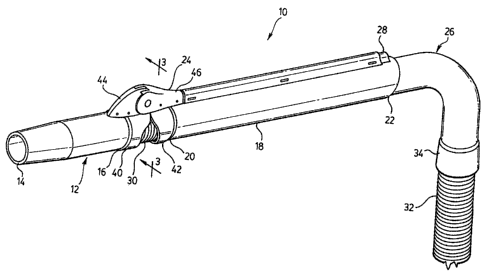
Figure 1 is a perspective view of a wand according to a first
embodiment to the instant invention;
CA 02647625 2008-12-19
-7-
Figure 2 is a exploded view of the wand of Figure 1;
Figure 3 is a cross-sectional view along the line 3-3 of Figure 1 of
the rotatable joint showing the lock in the locked position;
Figure 4 is a cross-sectional view along the line 3-3 of Figure 1 of
the rotatable joint showing the lock in the unlocked position;
Figure 5 is a cross-sectional view along the line 3-3 of Figure 1
showing the upstream tube pivoted at an angle of about 900 to the downstream
tube;
Figure 6 is a perspective view of an alternate embodiment
according to the instant invention;
Figure 7 is a side view of the embodiment of Figure 6;
Figure 8 is an enlarged view of the rotatable joint of Figure 7
showing the upstream tube bent at an angle of about 900 to the downstream
tube; and,
Figure 9 is a perspective view of a second alternate embodiment
according to the instant invention.
DESCRIPTION
Referring to the embodiment of Figures 1-5, wand 10 comprises
upstream tube 12, having upstream end 14 and downstream end 16, and
downstream tube 18, having upstream end 20 and downstream end 22.
Upstream tube 12 and downstream tube 18 are moveably connected together by
means of a rotatable joint 24. Upstream tube 12 and downstream tube 18 are
connected in fluid flow communication by a flexible fluid flow conduit 30. A
handle 26 for maneuvering wand 10 is preferably provided. Preferably, a lock
release actuator 28 is positioned adjacent handle 26.
CA 02647625 2008-12-19
-8-
Each of upstream and downstream tubes 12 and 18 may be of any
particular length and may be made of any rigid material (e.g. plastic or
metal).
Upstream end 14 of upstream tube 12 may be a nozzle for cleaning a surface.
Alternately, or in addition, it may be adapted to receive a surface cleaning
tool,
such as a surface cleaning head, additional extension tube, crevice cleaning
tool
or the like. Downstream end 22 of downstream tube 18 may be connected
directly with a cleaner body or may be connected thereto via a flexible hose
32.
Flexible hose 32 may be any flexible hose or conduit known in the
surface cleaning arts. For example, flexible hose 32 may be a plastic hose
with a
reinforcing member secured thereto in a spiral pattern.
As exemplified in Figure 2, the upstream end 34 of flexible tube 32
may have a handle 26 affixed thereto. Accordingly, handle 26 comprises an
intermediary component between downstream tube 18 and flexible hose 32. It
will be appreciated that, in an alternate construction, flexible hose 32 may
be
connected directly with downstream end 22 of tube 18. It will be appreciated
that
in such a construction, handle 26 may be incorporated as part of tube 18, tube
18
may be used as the handle or the handle may be a separate component
mounted thereto.
Flexible fluid flow conduit 30 (which is preferably a flexible hose)
connects downstream end 26 of upstream tube 12 in fluid flow communication
with upstream end 20 of downstream tube 18. Accordingly, in operation, air is
drawn into wand 10 via upstream end 14 and travels through upstream tube 12
(which define am upstream passage) through flexible fluid flow conduit 30,
through downstream tube 18 (which define am downstream passage) through
flexible hose 32 to the cleaning unit of a surface cleaning apparatus.
Additional
intermediary members may be provided in the fluid flow path from the dirty
fluid
inlet (e.g., the inlet of a surface cleaning head) to the cleaning unit.
CA 02647625 2008-12-19
-9-
It will be appreciated that the surface cleaning apparatus may be
any surface cleaning apparatus known in the art, such as an upright vacuum
cleaner, canister vacuum cleaner, backpack vacuum cleaner, wet-dry vacuum
cleaner or the like. If, for example, wand 10 is utilized with a canister or
backpack vacuum cleaner, then it will be appreciated that wand 10 may be
utilized as the extension tube that is steeringly connected to the surface
cleaning
head as is known in the art. Alternately, if the surface cleaning apparatus is
an
upright vacuum cleaner, then wand 10 may comprise an above floor cleaning
wand. Accordingly, it will be appreciated that hose 32 may be secured to a
surface cleaning apparatus by any means known in the art and wand 10 may
optionally be removably mounted to the surface cleaning apparatus.
Flexible fluid flow conduit 30 may be secured to tubes 12 and 18 by
any means known in the art. For example, upstream end 36 of conduit 30 may
be secured to downstream end 16 of tube 12 by a flexible cuff provided on end
36, which is slipped over end 16. Alternately, or in addition, upstream end 36
may be secured to tube 12 by an adhesive, an 0-ring clamp, a friction fit or
any
other means known in the art. Similarly, downstream end 38 of conduit 30 may
be secured to upstream end 20 of tube 18. Alternately, or in addition, a
collar or
cuff 40 may be provided on downstream end 16 of tube 12 and/or a collar or
cuff
42 may be provided on upstream end 20 of tube 18. In such a case, collar 40
may be used to secure upstream end 36 to tube 12 and collar 42 may be used to
secure downstream end 38 to tube 18. Collars 40, 42 may be separately molded
elements which are affixed to tubes 12, 18 by a friction fit, an adhesive, a
set
screw or the like. Conduit 30 may be slipped over end 16 of tube 12 and collar
40 mounted thereover so as to secure conduit 30 to tube 12. Alternately,
collar
40 may have a mounting member for receiving upstream end 36. Accordingly,
collar 40 could include an airflow passage there through. Similarly, collar 42
may
be used to secure downstream end 38 to tube 18. It will be appreciated by
those
CA 02647625 2008-12-19
-10-
skilled in the art that various mounting means may be used and that this
invention is not limited by the particular mounting means which is selected.
As exemplified in Figure 1, rotatable joint 24 comprises a first
connector 44 which is associated with downstream end 16 of tube 12 and the
second connector 46 associated with upstream end 20 of tube 18. First and
second connectors 44, 46 may be secured to tubes 12 and 18 by any means
known in the art and may be moveably mounted with respect to each other by
any means known in the art. Preferably, as exemplified in Figures 2-5, first
and
second connectors 44, 46 are pivotably mounted together.
As exemplified in Figure 2, tube 12 is provided with a flange 48
having openings 50. Flange 48 may be secured to tube 12 by any means known
in the art. For example, flange 50 may be secured to tube 12 by means of an
adhesive, welding, screws or it may be formed integrally as part as tube 12.
Connector 44 comprises first and second halves 52, 54, which may be secured
together by screws 56, rivets, an adhesive, welding or other means. Screw 56
passes through opening 58 in second half 54, through opening 50 and is
received in screw mount 60, which is provided on the inner surface of first
half 52
of first connector 44. Accordingly, flange 48 is used to secure first
connector 44
to tube 12. It will be appreciated that first and second halves 52, 54 may be
secured to tube 12 by any other means such as by an adhesive, welding,
mechanical attachment or other means directly connecting first and second
halves 52, 54 directly to tube 12.
Second connector 46 may be similarly mounted to tube 18. For
example, tube 18 may be provided with two flanges 62 each of which may be
provided with one or more openings 64. Second connector 46 may accordingly
comprise first and second halves 66, 68 and be secured together by means of
one or more screws 70 extending through opening 72 in second half 68, through
CA 02647625 2008-12-19
-11-
openings 64 in flanges 62, into screw mount 74 provided on the inner surface
of
first half 66.
First and second connectors 44, 46 may be pivotally secured
together by means of pivot screw 76. For example, each of first of second
halves
52, 54 may have a recessed surface 78 having an opening 80 therein. First and
second halves 66, 68 may also be provided with an opening 82 in mounting
portion 84 thereof. Mounting portions 84 are spaced apart when first and
second
halves 66, 68 are secured together on tube 18. Accordingly, once first and
second halves 52, 54 have been secured to tube 12, recessed surfaces 78 may
be inserted into the gap between mounting portions 84 and openings 80 and 82
aligned so that pivot screw 76 may extend through opening 82 in second half
68,
through opening 80 in second half 54, through opening 80 in first half 52 and
into
screw mount 86. Accordingly, when assembled, first and second connectors 44,
46 are secured to tubes 12 and 18 essentially as part of an exoskeleton, and
provide the pivot mount for pivotally connecting tubes 12 and 18 together.
It will be appreciated that other methods of pivotally connecting first
and second connectors 44, 46 may be used and that first and second connectors
44, 46 may be of varying designs.
Optionally, wand 10 includes a lock to secure wand 10 in at least
one orientation. For example, as shown in Figure 1, tubes 12 and 18 extend
linearly in accordance with a first mode or orientation such that the upstream
and
downstream flow passages provided therein extend essentially linearly (e.g.
along the same longitudinal axis). Preferably, a lock is provided to secure
tubes
12 and 18 in this fixed orientation, which is particularly useful for moving a
surface cleaning head over a floor to be cleaned. Any locking means known in
the art may be used.
Ax exemplified lock is shown in Figure 2. As exemplified therein,
first half 52 is provided with a C-shaped flange 88 on inner surface 90. A
similar
CA 02647625 2008-12-19
-12-
C-shaped flange may be provided on the inner surface of second half 54.
Accordingly, when assembled, the C-shaped flanges 88 define a pocket 92 for
receiving spring 94. Lock member 96 is moveably mounted in first connector 44
and is provided with extension 98 and locking portion 100. As shown in
particular in Figures 3 and 4, lock member 96 has an oblong internal opening
102
which seats on outer surface 104 of mount 106. It will be appreciated that a
mount 106 may be provided on the inner surface of recessed surface 78 of
second half 54. Extension 98 is preferably tubular in shape and is seated
within
one end of spring 94. Accordingly, spring 94 is positioned on extension 98 and
then inserted into pocket 92 thereby securing spring 94 in position. In order
to
accommodate locking member 96, a slot 108 may be provided in the
downstream side of first and second halves 52. First and second halves 66, 68
have a pocket 112 for receiving locking portion 100. Pocket 112 may be formed,
for example, by a C-shaped flange 110 provided on inner surface 116 of each of
first and second halves 66, 68.
As shown in Figure 3, the locking member is in the locked position.
Accordingly, spring 94 presses against extension 98 forcing locking member 96
in the downstream direction thereby maintaining lock member 96 in pocket 112.
Accordingly, locking portion 100 prevents first connector 44 from rotating
with
respect to the second connector 46. When locking portion 100 is removed from
pocket 112 (to the position shown in Figure 4), then first connector 44 may
rotate
with respect to second connector 46 (see for example Figure 5).
Locking member 96 may be moved between the locked position
shown in Figure 3 and the unlock position shown in Figure 4 by any means
known in the art, such as a lock release actuator. Preferably, lock release
actuator 28 is positioned distal to rotatable joint 24 and, more preferably,
adjacent to handle 26. Accordingly, a linkage 116 may be provided such that
lock
release actuator 28 may remotely actuate the lock. As exemplified, linkage 116
has lock release actuator 28 provided at one end thereof and driving member
CA 02647625 2008-12-19
-13-
118 provided at an opposed end thereof. Actuator 28 and driving member 118
may be integrally formed as part of linkage 116 or may be separate elements.
If
tube 18 is provided with two flanges 62, then flanges 62 may be spaced apart
to
define a channel within which linkage 116 is slideably mounted. Accordingly,
when linkage 116 is moved in the direction of arrow A in Figures 4 and 5, then
driving member 118 will drive locking portion to the unlocked position shown
in
Figure 4. It will be appreciated that only one flange 62 may alternately be
used
and, for example, linkage 116 may have a channel in its tube side in which
flange =
62 is slideably received.
Preferably, linkage 116 is biased to the locked position shown in
Figure 3. Accordingly, a biasing member may be provided to urge actuator 28
into the locked position. For example, inner surface 114 of first and/or
second
half 66, 68 may be provided with an abutment member 120. Similarly, linkage
116 may be provided with a spring mount or abutment member 122. Spring 124
may be positioned between abutment members 120, 122. Accordingly, when a
user desires to rotate upstream tube 12, the user may press actuator 28 moving
linkage 116 in the direction of arrow A thereby compressing spring 124 and
moving locking portion 100 into the unlocked position thereby permitting
upstream tube 12 to rotate. When a user releases actuator 12, spring 124 will
drive linkage 116 into the locked position. Concurrently, spring 94 will move
locking member into the locked position (i.e. driving locking portion 100 into
pocket 112).
A cap 126 or other cover may be provided for covering linkage 112.
Cap 126 may be secured to tube 18 by any means known in the art and may be
of any desired shape. For example, as exemplified in Figure 2, cap 126 is
designed to seat on flanges 62, such as by having members 128 removably
receivable in openings 130. Accordingly, cap 126 may be secured in place by
positioning cap 126 over flanges 62 and pressing downwardly such that
members 128 are received in openings 130. It will be appreciated that cap 126
CA 02647625 2008-12-19
-14-
may extend around all or a portion of tube 18 and may be secured thereto by
any
means known in the art, such as by means of an adhesive, welding, screws,
clamps or the like.
Figures 7 and 8 exemplify an alternate embodiment. Having similar
function are referred to using the same reference number in Figures 7 and 8.
In this alternate embodiment, first and second connectors 44, 46
are pivotably mounted together by pivot pin 132. First and second connectors
are
configured as collars which are provided on downstream end 16 of upstream
tube 12 and on upstream end 20 of downstream tube 18. Actuator 28 comprises
a trigger-like member which has an opening 134 for receiving a finger of a
user.
Locking member 96 is pivotably mounted about pivot pin 136 and has a hook 138
provided at distal end 140 of locking member 96. Hook 138 is removably
received in recess 142 of first connector 44. Arm 144 has a first end 146
secured
to linkage 116 and a second end 148 that is pivotably mounted to locking
member 96 by pivot pin 150. A channel 152 is provided in tube 18 in which a
portion of linkage 116 is seated so as to permit longitudinal movement in the
direction of arrow A of Figure 5. In operation, a user may use actuator 28 to
move linkage 116 longitudinally along tube 18 in the direction of arrow B
shown
in Figure 8. Movement of linkage 116 in the downstream fluid flow direction
causes arm 144 to apply a force to locking member 96 causing locking member
96 to pivot around pivot pin 116 thereby rotating hook 138 out of recess 142.
This
permits tube 12 to rotate about pivot pin 132 relative to tube 18.
It will be appreciated by those skilled in the art that linkage 116
may, for example, be a boden cable or any other member known in the art, which
will provide a pulling force on locking member 96. In addition, linkage 116
may be
secured to tube 18 by any means known in the art. Similarly, locking member 96
may engage first connector 44 by any other means known in the art.
CA 02647625 2008-12-19
-15-
A further alternate embodiment is shown in Figure 9. As shown
therein, first connector 44 is secured to downstream end 16 of tube 12 and is
generally Y-shaped, having two opposed flanges 154. Similarly, second
connector 46 is secured to upstream end 20 of tube 18 and has a Y-shaped end
having opposed flanges 156 which, when assembled, overlies flanges 154. Each
pair of flanges 154, 156 may be secured together by a pivot pin 158.
It will be appreciated that various different constructions may be
utilized for first and second connectors 44, 46. In particular, connectors 44,
46
may be formed as part of tubes 12 and 18 or may be separate members that are
manufactured separately and then attached thereto. In any such case,
connectors 44, 46 are associated with tubes 12 and 18 and provide the movable
joint. Accordingly, when connectors 44, 46 move with respect to each other,
tubes 12 and 18 move with respect to each other. It will be appreciated that
movements other than pivotal may be utilized. For example, one member 44, 46
may translate as well as rotate with respect to the other connector 44, 46.
In addition, an actuator may be provided adjacent the lock or distal
thereto. If the actuator is provided distal to the lock, then it is preferably
positioned proximate the handle. Preferably, the actuator is positioned such
that
a user may release the lock while holding the handle.
It will be appreciated that certain features of the invention, which
are, for clarity, described in the context of separate embodiments or separate
aspects, may also be provided in combination in a single embodiment.
Conversely, various features of the invention, which are, for brevity,
described in
the context of a single embodiment or aspect, may also be provided separately
or in any suitable sub-combination.
Although the invention has been described in conjunction with the
specific embodiments hereof, it is evident that many alternatives,
modifications
and variations will be apparent to those skilled in the art. Accordingly, it
is
CA 02647625 2008-12-19
-16-
intended to embrace all such alternatives, modifications and variations that
fall
within the spirit and broad scope of the appended claims. In addition,
citation or
identification of any reference in this application shall not be construed as
an
admission that such reference is available to the present invention.