Note: Descriptions are shown in the official language in which they were submitted.
CA 02647658 2013-08-22
LATCH SYSTEM FOR SLIDING PANEL IN VEHICLE
Background
[0002] This disclosure relates to a latch system, and more particularly a
latch
system for a panel such as a sliding panel in a vehicle.
[0003] It is known to provide for sliding panels, for example doors such as a
tambour door, in vehicles used to cover storage enclosures. Such known sliding
doors
typically have a detent or a latch to retain the door in a desired position.
However, such
known latch systems occupy space in the vehicle, do not provide sufficient
amount of
latching or retaining force, and do not otherwise realize certain advantageous
features
(and/or combinations of features).
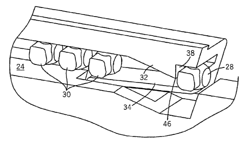
[0004] It would be desirable to provide a sliding panel, door or the like of a
type
that includes any one or more of these or other advantageous features: provide
a panel that
can be articulated to expose or cover a storage space, controls, a display, a
user interface, a
mirror, or the like; provide a latch system for an articulated panel that can
be secured in a
closed position; provide a latch system that maximizes storage or functional
options and
arrangements by not requiring additional bulkhead or structural members
between its lateral
edges; provide a latch system that provides a positive engagement between the
panel and
the base; and meet Federal Motor Vehicle Standards Specification 201. (FMVSS
201) and
reasonable release efforts to slide the panel.
= Description of the Drawings
[0005] FIG. I is a perspective view of a base configured as a vehicle console
with
an articulating panel in the form of a slidingpanel.
[0006] FIGS. 2-5 arc fragmentary side perspective views of the base, panel,
and
latch system.
[0007] FIG. 6 is a fragmentary front perspective view of the base, panel, and
latch
system.
[0008] FIG. 7 is a fragmentary side perspective view of the base, panel, and
latch
system.
-1-
CA 02647658 2008-10-16
WO 2007/123944 PCT/US2007/009467
[0009] FIGS. 8 and 9 are views of a track according to an exemplary
embodiment.
Summary
[0010] According to an exemplary embodiment, a vehicle trim component
includes a base which includes a track. A panel is movable between a first
position and a
second position has at least one guide member at its lateral edge that engages
the track as
the panel is moved between the first position and the second position. A latch
system
includes a catch and a biasing member. The guide member engages the catch when
the .
panel is in the first position.
[0011] According to another exemplary embodiment, a vehicle console includes a
housing structure having side walls and defining an opening. A track coupled
to the
housing structure is proximate the opening. A panel is movable between a first
position and
a second position has at least one guide member at its lateral edge that
slidably engages the
track as the panel is moved between the first position and the second
position. A latch
system includes a catch and a biasing member, wherein the guide member engages
the catch
when the panel is in the first position.
[0012] According to a further exemplary embodiment, a vehicle trim component
includes a.base which includes a track. A panel is movable between a first
position and a
second position has at least one guide member at its lateral edge that
slidably engages the
track as the panel is moved between the first position and the second
position. A latch
system disposed at the lateral edge of the panel to latch the panel in the
first position.
[0013] The vehicle trim component further relates to various features and
combinations of features shown and described in the disclosed embodiments.
Other ways in
which the objects and features of the disclosed embodiments are accomplished
will be
described in the following specification or will become apparent to those
skilled in the art
after they have read this specification. Such other ways are deemed to fall
within the scope
of the disclosed embodiments.
Description
[0014] FIGS. 1 and 2 illustrate a base 10 and a panel 12 coupled to the base
10 by
a latch system 14. The base 10 can be configured to be mounted in a vehicle
interior and, in
the illustrated exemplary embodiment, is a console 50 for a vehicle (not
shown). Console
50 typically is coupled to a vehicle floor between two seats. According to an
exemplary
embodiment, console 50 is configured to provide a storage area and an arm rest
for an
occupant of one or both seats. Console 50 is a generally prismatic structure
with a front
-2- =
CA 02647658 2008-10-16
WO 2007/123944
PCT/US2007/009467
wall, a rear wall, two opposed and generally symmetrical, side walls and a top
surface.
Console 50 includes two side panels 18 and a rear panel. Side panels 18 each
provide a side
wall of console 50 and a portion of the rear wall, the front wall and the top
surface. Rear
panel provides a portibn of the rear wall and the top surface. Console 50 also
includes a
bin 20, an inner partition'or insert, tracks, and an opening 13. The door
panel 12 is
configured to close the Opening 13 in console 50.
100151 Opening 13 provided in console 50 may be selectively closed with the
door
panel 12. The door panel 12 can be a flexible or articulated door. According
to an
exemplary embodiment, panel 12 is a tambour door and rides on tracks or rails
16. Tracks
16 may be coupled to panels 18 or integrally formed with panels 18. An insert
(e.g.,
. interior, partition, bin, liner etc.) may be provided within console 50
that is selectively
=
accessible through opening 13.
[0016] As will be understood from FIGS. 3-7, the track 16 is configured to
receive
a portion of the panel 12 to provide support and an engagement for the panel
12. The track
16 includes a first (e.g., upper) surface 22 and a second (e.g., lower)
surface 24. A
projection 26 (e.g., rib, etc.) extends from an inner surface of track 16 and
is configured to
provide alignment of the panel 12 and reduce the side to side movement of the
panel 12.
[0017] The panel 12 engages the track 16 of the console 50 and is coupled or
retained in place, at times, by the latch system 14. The panel 12 comprises a
front support
or guide member 28 and one or more subsequent support or guides members 30.
According
to an exemplary embodiment, the panel 12 is shown as a "tambour" door having a
plurality
of segments connected by a web (i.e., a "living hinge"). The guide members are
sometimes
referred to as balls or beads with tambour door applications. One or more of
the segments
may include ends that form the lateral sides (boundary, edge, etc.) of the
panel 12 and
comprise the support or guide member(s). At least the forward most guide
member 28 is
configured to engage the latch system 14.
[0018] The latch system 14 includes a catch 32 and a biasing member 34 and is
configured to minimize structure needed to retain the panel in a closed
position.
[0019] The catch 32 is configured to retain the panel 12 in a desired position
and
to require a predetermined minimum level or amount of force to unlatch the
panel. The
catch 32 includes a ramped surface 36 and a retaining surface 38. According to
an
exemplary embodiment, the retaining surface 38 is at an acute or right angle
relative to the
upper surface 22 and at an acute angle relative to the ramped surface 36.
According to
-3-
CA 02647658 2008-10-16
WO 2007/123944 PCT/US2007/009467
alternative embodiments, the retaining surface 38 may be at any of a variety
of angles to
provide the desired retaining performance. According to a preferred
embodiment, the catch
32 is integrally molded with at least a portion of the console 50 (e.g., as a
one piece, unitary
component) such as With the track 16. According to an alternative embodiment,
the catch
32 is a separate component that is attached to the console 50 and/or track 16.
[0020] The biasing member 34 is configured to bias an engagement portion of
the
panel 12 against the ramped surface 36 and into engagement with the retaining
surface 38.
According to an exemplary embodiment, the biasing member 34 is a spring (e.g.,
a leaf
spring as shown in FIG. 3-7) coupled to one of the console 50 and the track
16. According
to an alternative embodiment, the biasing member 34 is integrally formed with
the console
50 or the track 16 as a one-piece, unitary component. Alternatively, any of a
variety of
resilient members may be used to bias the panel 12 into engagement and
securement with
the catch 32.
[0021] Referring to FIG. 8, a track component 40 is shown according to an
exemplary embodiment. The track component 40 comprises a track 41, a flexible
member
or beam 42 such that the biasing force is provided by beam 42, and a biasing
member 34,
such as a wire spring (or a leaf spring, etc.) located below, and in
supporting contact with,
the beam 42. As such, the resistance against the guide member 28 moving along
the ramp
surface 36 is provided by an upward force generated by the resilient nature of
the beam 42
and (e.g., mostly) by the spring 34.
[0022] The panel 12 is movable between a first position and a second position.
In
the first or "closed" position, the panel 12 inhibits access (physical and/or
visual) (e.g.,
covers, conceals, protects, screens, obscures, masks, etc.) to at least a
portion of the console
50. In the second or "open" position, the panel 12 allows access (physical
and/or visual)
(e.g., uncovers, exposes, reveals, discloses, etc.) to at least a portion of
the console 50. For
example, the panel 12 in the open position allows access to a bin 20 which can
be used for a
storage area, a cup holder, a vehicle control, a display, user interface
items, or a
combination of same. According to a preferred embodiment, the panel 12 is
configured for
translating or sliding movement. .When in the second position, the panel 12
may be coiled
or wrapped to minimize space it occupies.
[0023] To secure or latch the panel 12, the panel 12 is moved or slid along
track 16
until front guide member 28 encounters the ramp surface 36. Additional force
is then
required to continue sliding the panel 12 along ramped surface 36 to overcome
the upward
-4-
CA 02647658 2008-10-16
WO 2007/123944 PCT/US2007/009467
force generated by biasing member 34. Once front guide member 28 passes the
end or edge
46 of the catch 32, the biasing member 34 pushes or snaps the member 28 into
place and the
panel 12 is latched or retained in place by the retaining surface 38.
[0024] To open the panel 12, the user pushes (downward) against and flexes the
panel 12 to overcome the force generated by the biasing member 34 so that the
guide
member 28 clears the edge 46 of the catch 32 (i.e., "unlatch"). The panel 12
can then be
slid towards the first or open position. According to a preferred embodiment,
the front
guide member 28 is spaced apart from the subsequent guide members 30 so that
the panel
12 can flex sufficiently, with a desired amount of force by the user, to clear
the catch 32.
[0025] The guide members 28, 30 may be configured (e.g., shaped, sized,
contoured, etc.) to provide the desired sliding and latching performance.
Also, the angle of
the ramp surface 36 relative to the track 16 may be any of a variety of angles
depending on
the desired amount of force to engage the latch.
[0026] The base 10 is shown in the illustrated embodiment as a center console
50,
mounted between a pair of seats, but the base 10 may be any of a variety of
structures,
including an instrument panel, a door, an overhead system or headliner, trim
panels, vehicle
trim components or panels, or the like.
[0027] The particular materials used to construct the exemplary embodiments
are
also illustrative. For example, injection molded high density polyethylene is
one method
and material for making the panel 12, and injection molded thermoplastic
elastomer is
another method and material for making the panel 12. However, other materials
can be
used, including other thermoplastic resins such as polypropylene, other
polyethylenes,
acrylonitrile butadiene styrene ("ABS"), polyurethane nylon, any of a variety
of =
homopolymer plastics, copolymer plastics, plastics with special additives,
filled plastics,
etc. Also, other molding operations may be used to form these components, such
as blow
molding, rotational molding, etc. Components of the base 10 and panel 12 can
also be
manufactured from stamped alloy materials such as steel or aluminum.
[0028] For purposes of this disclosure, the term "coupled" means the joining
of
two components (electrical or mechanical) directly or indirectly to one
another. Such
joining may be stationary in nature or movable in nature. Such joining may be
achieved
with the two components (electrical or mechanical) and any additional
intermediate
members being integrally formed as a single unitary body with one another or
with the two
components or the two components and any additional member being attached to
one
-5-
CA 02647658 2008-10-16
WO 2007/123944 PCT/US2007/009467
=
another. Such joining may be permanent in nature or alternatively may be
removable or
releasable in nature .
[0029] Although a number of exemplary and alternative embodiments have been
described in detail, it is to be understood that the trim component is not
limited to the details
of construction and the arrangement of the components set forth in the
forgoing description
or illustrated in the drawings. It is also to be understood that the
phraseology and
terminology employed herein is for the purpose of description and should not
be regarded as
limiting. For example, while the components of the disclosed embodiments will
be
illustrated as a panel designed for a vehicle interior, the features of the
disclosed
embodiments have a much wider applicability. For example, the latch design is
adaptable
for other storage-units, bins, containers, and other office, home, or
educational products
which employ a storage space configured to have a panel that is moveable to
inhibit visual
and physical access to it. Further, the size of the various components and the
size of the
containers can be widely varied. Also, it is important to note that the terms
"base," "panel,"
and "latch" are intended to be broad terms and not terms of limitation. These
components
may be used with any of a variety of products or arrangements and are not
intended to be
limited to use with vehicle interior applications.
[0030] It is also important to note that the construction and arrangement of
the
elements of the latch system as shown in the exemplary embodiments is
illustrative only.
Although only a few embodiments of the vehicle trim component have been
described in
detail in this disclosure, those skilled in the art who review this disclosure
will readily
appreciate that many Modifications are possible (e.g., variations in sizes,
dimensions,
structures, shapes and proportions of the various elements, values of
parameters, mounting
arrangements, use of materials, colors, orientations, etc.) without materially
departing from
the novel teachings and advantages of the subject matter recited. For example,
elements
shown as integrally formed may be constructed of multiple parts or elements
show as
multiple parts may be integrally formed, the operation of the interfaces may
be reversed or
otherwise varied, the length or width of the structures and/or members or
connectors or
other elements of the system may be varied, and the nature or number of
adjustment
positions provided between the elements may be varied (e.g. by variations in
the number of
engagement slots or size of the engagement slots or type of engagement). It
should be noted
that the elements and/or assemblies of the system may be constructed from any
of a wide
variety of materials that provide sufficient strength or durability, in any of
a wide variety of
-6-
CA 02647658 2008-10-16
WO 2007/123944
PCT/US2007/009467
colors, textures and combinations. Accordingly, all such modifications are
intended to be
included. Other substitutions, modifications, changes and omissions may be
made in the
design, operating conditions and arrangement of the exemplary embodiments.
-7-