Note: Descriptions are shown in the official language in which they were submitted.
CA 02647792 2008-09-24
WO 2007/112255 PCT/US2007/064611
RACK FOR CONTAINERS
BACKGROUND OF THE INVENTION
The present invention relates generally to a rack for holding objects and
more particularly to a rack for holding water bottles.
A typical home delivery system for 3 and 5-gallon bottles of drinking water
involves a delivery truck, racks, bottles and a driver. The delivery truck is
usually
configured with several bays on each side with each bay having a rollup door
to
enclose the product. Inside each bay one or more racks are stored filled with
bottles.
The racks are typically loaded and unloaded with bottles outside the bays.
Fork
trucks are used to move the racks in and out of the bays.
The racks have traditionally been made from metal and more recently from
plastic. The plastic racks tend to be modular in design with each component
making
up a layer of the rack. The layer can hold four bottles in a two by two
arrangement
or eight bottles in a four wide by two deep arrangement. A two deep
arrangement is
for 5-gallon bottles whereas 3-gallon bottles will be three deep in the same
space.
The plastic components can sit on top of an existing pallet for transport or
can
incorporate runners or blocks into the bottom layer to eliminate the need for
a pallet.
In either case pallet trucks and jacks are the means for moving the racks. The
modular design allows the distributor to stack them to any height but usually
three to
five layers high. At five layers the rack can hold up to forty 5-gallon
bottles. Plastic
racks have gained acceptance because they have proven to be more durable and
the
modular design allows for easy repair.
Leaking containers are a problem within the existing system. Testing has
shown that the bouncing up and down of the bottles in the racks is a
significant
cause of leaking containers. Whenever the truck is moving the rack and bottles
experience vibration and therefore relative movement. The movement at the
contact
points in combination with other environmental factors such as dirt and dust
eventually weakens the bottle resulting in a hole or crack. Testing has shown
that the
softer plastic racks can reduce this, but a push toward lighter and thinner
bottles to
reduce costs has made the problem significantly worse in recent years.
1
CA 02647792 2008-09-24
WO 2007/112255 PCT/US2007/064611
One company has tested a metal (steel) rack that reduces the leaking
container problems associated with the rack. This new rack incorporates a
mechanical clamping device that locks each bottle in place during
distribution. A
steel tree within the rack links all the bottle pockets so that one large
lever arm can
lock and unlock all the bottles within the rack with one movement. A drawback
to
this rack is the force required to effectively clamp all the bottles in a
rack. Testing
has shown that the locking force from the tree on each bottle can average 100
lbs.
For a 40-bottle rack this results in a total locking force of 4000 lbs. Cams
and the
length of the lever arm greatly reduce the input force needed from the driver
but the
force is still considerable. Obviously the driver will be resistant to using a
system
that increases his work load. Another problem with this design is that the
locking
force on individual bottles can vary by a large amount. This is due to a fixed
travel
height for the tree that cannot adjust to the varying bottle sizes and shapes
as well as
pocket to pocket variances within the rack.
In the current design the lever arm sticks out of the bay door when in the
unlocked position. This prevents the bay door from being closed when in the
unlocked position. This feature would guarantee that the locking device is
used at
every stop.
A second advantage of locking down the bottles is that it prevents the bottles
from "walking" out of the racks during transport. In the worst case of
walking, the
bottle cap will rest against the inside of the bay door. When the driver tries
to lift the
door the cap can jam against the raised corrugations on the inside of the
door. Much
time and effort is required to solve this problem each time it occurs.
However, even with the existing clamping system, there is still the
possibility that the driver will deliver bottles to the customer, then return
to the truck
and drive away while forgetting to clamp the bottles and close the door at
all. When
this occurs, the bottles can fall out of the vehicle, littering the roadway
and possibly
causing damage to other vehicles.
SUMMARY OF THE INVENTION
The present invention provides a rack for securing objects, such as
containers, and more particularly water bottles. The rack defines a plurality
of bays
2
CA 02647792 2008-09-24
WO 2007/112255 PCT/US2007/064611
into which one or more containers are received. An expandable clamp including
an
inflatable chamber is disposed adjacent each bay and expands into the chamber
to
secure the containers within the bay.
When installed on a vehicle, a pump (or other air source) may be activated
automatically whenever the door is closed and/or whenever the vehicle is
shifted
into gear (or when the engine is started). Activation of the pump inflates the
expandable chambers, thereby locking containers in place in the bays. This
prevents
movement and vibration and reduces damage to the bottles during transportation
BRIEF DESCRIPTION OF THE DRAWINGS
Other advantages of the present invention will be readily appreciated as the
same becomes better understood by reference to the following detailed
description
when considered in connection with the accompanying drawings wherein:
Figure 1 is a perspective view of a rack according to a first embodiment of
the present invention holding a plurality of containers.
Figure 2 is a perspective view of the rack of Figure 1 with an additional
layer.
Figure 3 is an exploded view of the rack of Figure 1.
Figure 4 is a front view of the rack of Figure 1.
Figure 5 shows the rack of Figure 4 with the chambers expanded.
Figure 5A is an enlarged view of one of the chambers expanded and
contracted adjacent an empty bay.
Figure 6 is a side view of the rack of Figure 1.
Figure 7 is a side view of a rack of several of the layers of Figure 1 and a
schematic of the system for operating the rack in a vehicle.
Figure 8 is a perspective view of a rack according to a second embodiment.
Figure 9 is an exploded view of the rack of Figure 8.
Figure 10 is a front view of the rack of Figure 8.
Figure 11 illustrates the rack of Figure 10 with the chamber expanded.
Figure 12 is a perspective view of a rack according to a third embodiment.
Figure 13 is an exploded of the rack of Figure 12.
Figure 14 is an exploded view of a rack according to a fourth embodiment.
3
CA 02647792 2008-09-24
WO 2007/112255 PCT/US2007/064611
Figure 15 is a section view through two of the bays of the rack of Figure 15
containing bottles, with the clamp in the released position.
Figure 16 is similar to Figure 15, with the clamp in the engaged position.
Figure 17 is a perspective view of a rack according to a fifth embodiment.
Figure 18 is an exploded view of the rack of Figure 17.
Figure 19 is a section view through two of the bays of the rack of Figure 17
containing bottles, with the clamps in the released position.
Figure 20 is similar to Figure 19, with the clamps in the engaged position.
Figure 21 is a bottom perspective view of a rack according to a sixth
embodiment.
Figure 22 is a bottom perspective view of the upper section of the rack of
Figure 21.
Figure 23 is an exploded view of the upper section of Figure 22.
Figure 24 is a rear view similar to Figure 23.
DETAILED DESCRIPTION OF THE PREFERRED EMBODIMENT
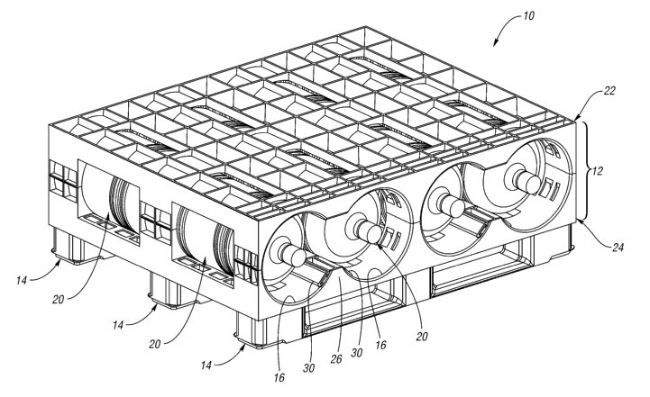
A rack 10 according to a first embodiment of the present invention is shown
in Figure 1. The rack 10 includes a first layer 12 (or first "shelf")
supported on a
plurality of supports 14. The first layer 12 defines a plurality of generally
cylindrical bays 16. A pair of containers 20, in this case a pair of five
gallon water
bottles 20, can be received within each bay 16. The first layer 12 includes an
upper
section 22 and a lower section 24. The lower section 24 includes a partial
divider 26
between each adjacent pair of bays 16. An expandable, inflatable clamping
chamber
is mounted on each side of the divider 26 adjacent the bottles 20. The
25 expandable chambers 30 are elongated, flexible pneumatic bladders or seals
that
extend from the front of the rack 10 to the rear of the rack 10.
As shown in Figure 2, the rack 10 can be expanded by adding additional
shelves, such as a second layer 12', stacked on top of the first layer 12.
Both layers
12, 12' are supported on the supports 14 above the floor, such that the rack
10 can be
30 lifted and moved with a forklift. As explained above, it is anticipated
that three to
five layers 12 would be installed in each bay of a delivery truck.
4
CA 02647792 2008-09-24
WO 2007/112255 PCT/US2007/064611
Figure 3 is an exploded of the rack 10 in Figure 1. The upper section 22
includes semi-cylindrical recesses 32 defined between column portions 36 and
partial divider 34. The partial 34 divider and column portions 36 extend
downwardly from a deck 40. The upper section 22 and lower section 24 are each
integrally molded as a single piece of plastic, such as polypropylene, or
another
suitable material.
The lower section 24 similarly includes adjacent pairs of semi-cylindrical
recesses 42 defined between column portions 44 and the partial divider 26. The
partial divider 26 and column portions 44 extend upwardly from a deck 46. The
partial divider 26 includes mounting areas 50 to which the expandable chambers
30
are mounted. Each of the supports includes a plurality of columns 56 connected
by
struts 58. The columns 56 mount to the underside of the deck 46 of the lower
section 24. The bays 16 (Figure 1) are defined by the semi-cylindrical recess
42 on
the lower section 24 and the semi-cylindrical recesses 32 on the upper section
22.
Figure 4 is a front view of the rack 10 of Figure 1 when the expandable
chambers 30 are deflated. With the expandable chambers 30 in the deflated
condition, the bottles 20 can be inserted into and removed from the bays 16.
Figure 5 illustrates the rack 10 with the expandable chambers 30 expanded.
The expandable chambers 30 are expanded and inflated by air pressure inside
the
expandable chambers 30. For example, the expandable chambers 30 are inflated
to a
pressure that will result in a force of about one-hundred pounds locking each
of the
bottles 20 inside the bays 16. This effectively clamps the bottles 20 in the
rack 10,
preventing damage to the bottles 20 from the vibration during transport.
Before
moving the bottles 20 from the rack 10, expandable chambers 30 must be
deflated.
The bottles 20 can then be slid out of the bays 16. Because the expandable
chambers 30 are flexible, they conform to the shape of the bottles 20 and will
not
damage the bottles 20. The expandable chambers 30 also prevent the bottles
from
sliding out of the bays 16 during transport.
Figure 5A is an enlarged view of one of the chambers 30 in the mounting
area 50 adjacent an empty bay 16. The chamber 30 is shown in both the
uninflated
condition, where it does not protrude into the bay, and the chamber 30' is
shown in
phantom in its inflated condition. Note that the expanded chamber 30'
protrudes
5
CA 02647792 2008-09-24
WO 2007/112255 PCT/US2007/064611
into the bay 16 because there is no bottle 20 in Figure 5A to prevent it from
doing
so. Figure 6 is a side view of the rack 10 with the bottles 20.
Figure 7 is a schematic side view of a rack 10 of several layers 12 containing
bottles 20 installed in a truck 64. Figure 7 also schematically shows a pump
60 (or
compressor), a pressurized tank 61, a valve 62 and a sensor 63 for actuating
the rack
10. The sensor 63 is installed adjacent the door 66 of the truck 64. The pump
60
maintains pressure in the tank 61 within a set range in a known manner. The
sensor
63 controls the valve 62 (such as a three-way valve) based upon whether the
door 66
is opened or closed. The valve 62 vents pressure from the rack 10 when the
door 66
is opened and then pressurizes the rack 10 with pressure from the tank 61 when
the
door 66 is closed. The tank 61 is connected to the rack 10 via conduits 72
each
having a quick disconnect 68 formed thereon for connection to a complementary
coupling 70 on the rack 10. Note that a single roll-up door 66 is shown, but
one or
more swinging doors 66 could also be used.
In operation, the user loads the bottles 20 into the rack 10 on the truck 64
and
then closes the door 66. Upon detecting that the door 66 is closed, the sensor
63
activates the pump 60 which supplies pressure to the expandable chambers 30 as
shown in Figure 5. This locks the bottles 20 in place in the bays 16 in the
rack 10,
preventing vibration, damage and movement of the bottles 20 during shipment.
When the door 66 is open, the sensor 63 detects the opening of the door 66 and
causes the pump 60 to release the air pressure in the expandable chambers 30
which
return to the position shown in Figure 4. The bottles 20 can then be removed
from
the bays 16 for delivery. Empty bottles 20 can also be loaded on the rack 10.
When
the door 66 is closed again, the expandable chambers 30 are again inflated.
Thus,
the system is automated and requires no user interaction.
As a first alternative, the pump 60 could be eliminated. For local delivery
trucks, it is possible to store sufficient pressure in the tank 61 for at
least one
delivery route. The tank 61 would be repressurized when the truck 64 returns
to the
distribution center to return the empty bottles 20 and pick up more full
bottles 20.
As a second alternative, the pump 60, tank 61 and valve 62 could all be
eliminated from the truck 64, if the truck 64 is transporting the bottles 20
from a
warehouse to a distribution center, or for some other reason, no bottles 20
will be
6
CA 02647792 2008-09-24
WO 2007/112255 PCT/US2007/064611
removed from the racks 10 during transportation. In this situation, the racks
10 can
be pressurized at the warehouse before being loaded on the truck 64. The
pressurized racks 10 remain pressurized without any additional outside source
of
pressure to protect the bottles 20 during shipment and during
loading/unloading at
the warehouse and distribution center.
The valve 62 could also be activated based upon a gear/parking brake sensor
65 (or other vehicle operating state) that activates the valve 62 based upon
the truck
64 being shifted into and out of a parking gear or based upon the
application/release
of a parking brake. Therefore, even if the driver forgets to close the door
66, the
racks 10 will be pressurized and the bottles 20 will be locked in place when
the
parking brake is released and/or when the truck 64 is shifted into gear.
Alternatively, a motion or speed sensor could pressurize the racks 10 whenever
motion of the vehicle 64 is sensed.
A rack 110 according to a second embodiment is shown in Figure 8. The
rack 110 is similar to the rack 10 in structure and operation except as
otherwise
described below or shown in the drawings. Corresponding components will be
designated with reference numerals prefixed with a"l." In this rack 110, the
expandable chamber 130 is positioned on top of the partial divider 126. As
shown
in Figure 9, the mounting area 150 is formed on the top of the partial divider
126.
Figure 10 is a front view of the rack 110 with the expandable chambers 130
deflated.
In this position the bottles 120 are not in contact with the expandable
chamber 130
and can be easily inserted into or removed from the bays 116. Upon inflation
of the
expandable chambers 130 in the manner described above, the expandable chambers
130 each contact the bottles 20 in two adjacent bays 116 as shown in Figure
11.
This arrangement in the rack 110 reduces the total number of expandable
chambers
130 that are necessary.
Figure 12 illustrates a rack 210 according to a third embodiment. Except as
otherwise described below or shown in the drawings, the rack 210 is similar in
structure and operation to racks 10, 110. In this rack 210, the cylindrical
bays 216
are defined on either side of the partial divider 226 and an expandable
chamber 230
is provided for each bay 216. As shown in Figure 13, the supports 214 snap-fit
into
7
CA 02647792 2008-09-24
WO 2007/112255 PCT/US2007/064611
the lower section 224 which in turn snap-fits into the upper section 222 for
easy
assembly of the rack 210.
Alternate arrangements and locations of the expandable chambers 30, 130,
230 are also possible. For example, the expandable chambers 30, 130, 230 may
be
placed on the upper halves 22, 122, 222 of the racks 10, 110, 210 so that the
pressure
exerted by the expandable chambers 30, 130, 230 is in the same direction as
the
gravity acting on the bottles 20. Alternatively, the expandable chambers 30,
130,
230 could be positioned inside or behind a wall of a rack section, such that
expansion of the chamber deforms the plastic wall, thereby clamping the bottle
20
inside the bay.
Figure 14 is an exploded view of a rack 310 according to a fourth
embodiment. Each shelf or layer 312 (one shown) is integrally molded as a
single
piece, not in halves, and supported on a plurality of supports 314. In this
embodiment, the expandable chambers 330 are mounted inside and behind plastic
clamps. Referring to Figure 15, which is a section view through two of the
bays 316
containing bottles 20, the expandable chamber 330 is positioned in a mounting
recess 350 in an upper wall of the first layer 312 (it could alternatively be
positioned
in the lower wall directed upwardly). A clamp 332 is slidably mounted in the
mounting recess 350 over the expandable member 330.
When the expandable member 330 is expanded as shown in Figure 16, the
expandable member 330 urges the clamp 332 downwardly against both bottles 20
in
both bays 316. Although the clamp 332 is relatively rigid, the flexible
expandable
member 330 behind it provides a resilient clamping force on the bottles 20,
which
prevents damage to the bottles 20.
Figure 17 is a perspective view of a rack 410 according to a fifth
embodiment. The rack 410 includes a single, integrally molded shelf or layer
412
(again, it could alternatively be formed in halves, as in the first several
embodiments). Referring to Figure 18, a cover 417 above each pair of bays 416
closes a pair of elongated chambers 418 molded into the upper portion of the
layer
412 (again upper portion is preferred, but the lower portion could also be
used). One
expandable wall 419 of each elongated chamber 418 is flexible and expandable,
such as by being molded with corrugations. When the cover 417 is secured (via
8
CA 02647792 2008-09-24
WO 2007/112255 PCT/US2007/064611
adhesive, welding or other known techniques), each elongated chamber 418,
including expandable wall 419 and together with the cover 417, formed the
expandable chamber 430 in this embodiment. When pressure inside the expandable
chambers 430 is increased, the expandable walls 419 resiliently bear against
the
bottles 20 as shown in Figure 20.
Figure 21 is a bottom perspective view of a rack 510 according to a sixth
embodiment. Although only one layer 512 is shown, additional layers 512 would
be
stacked, as in all the embodiments. In this rack 510, a single expandable
chamber
530 winds around through all of the bays 516. Thus, only a single connection
to the
single expandable chamber 530 is necessary.
Figure 22 is a bottom perspective view of the upper section 522 of the rack
510 of Figure 21. The expandable chamber 530 winds around through all of the
bays 516 in a serpentine pattern, such that the single expandable chamber 530
can
contact all of the bottles 20 (Figure 1).
Figures 23 and 24 are front and rear exploded views, respectively, of the
upper section 522. As shown, the mounting area 550 passes through each of the
bays 516 at least once, although different patterns could be used.
Although the invention is particularly useful for water bottles 20, other
containers and other objects could be secured in a rack in a similar fashion
using the
invention described above. It should be noted that variations in many of the
features
between the several embodiments described above are largely interchangeable.
For
example, the expandable chambers 30, 130, 230, 330, 430, 530 could be directed
upwardly, downwardly, horizontally or diagonally against one or more rows of
bottles. The layers 12, 112, 212, 312, 412, 512 could be molded as one piece,
multiple pieces and could optionally snap together. The invention is not
limited to
the particular combinations of optional features shown in the several
embodiments.
It is intended that all of the embodiments shown, or even combinations of
several of
the embodiments shown could be stacked and used together in the arrangement
and
system shown in Figure 7. Suitable expandable chambers 30, 130, 230, 330, 530
are available commercially.
Although a preferred embodiment of this invention has been disclosed, a
worker of ordinary skill in this art would recognize that certain
modifications would
9
CA 02647792 2008-09-24
WO 2007/112255 PCT/US2007/064611
come within the scope of this invention. For that reason, the following claims
should be studied to determine the true scope and content of this invention.